Transcription
Software Requirements Specification (SRS)Project SCC - Group 1Authors: Andy Ashton, Ian Guswiler, Lauren Malik, Ibraheem Saleh, Yash PatelCustomer: Mr. Eric Winder, Ford Motor CompanyInstructor: Dr. James Daly1IntroductionThis document contains the detailed specification and requirements essential to design theScalable Cruise Control by Ford Motor Company. This section contains the purpose of thisdocument, description of the application domain, and definitions for any abbreviations usedthroughout this document. The software requirements of the system are described in detail usingtextual descriptions as well as visual models including use case diagrams, class diagrams, andstate diagrams. Finally, a complete prototype of the system is introduced with detailedinstructions regarding its usage and sample scenarios representative of the system. Referencesand contact information can be found at the last section of this document.1.1PurposeThe purpose of the Software Requirements Specification is to define and specify in detail therequirements needed to create the Scalable Cruise Control software for the Ford MotorCompany. The document also helps to complete the agreement between the developer andcustomer so that the specified requirements are being implemented to the customer’s satisfaction.The intended audience are developers and management that will use this document to validatethat the system is being built according to the client’s requirements.1.2ScopeThe purpose of the Scalable Cruise Control (SCC) system is to allow drivers to maintain speed ordistance from a forward vehicle safely. This system is implemented as an embedded system forautomobiles. Users will benefit from the aversion of accidents otherwise caused by hackers,driver error or other compromised vehicle system. The main goal of the system would be todecrease the number of accidents caused by cruise control.Subsystems of the system would be simple cruise control, following distance1
management, and automatic emergency braking. All would be implemented in thesystem as a final product. The SCC software system will provide a user with anautomated response to possible safety threats while driving. It will do this throughthe prioritization of commands input by the user such as a set cruise speed, as wellas following distance to other vehicles, and the use of the automaticemergency brake. The system will be extensible such that it will take in to accountadditional future features that can make use of the same base functionality, curvespeed assist, etc. The SCC will not ensure the safety of all occupants in case anaccident does occur, it is only a software system added on to a vehicle to preventsuch accidents from occurring.1.3Definitions, Acronyms, and AbbreviationsTermDescriptionScalable CruiseControl (SCC)The Scalable Cruise Control system being designed and implemented.Simple Cruise(SC)Subsystem of the SCC system that is enabled by the driver and allows acruise speed to be set and maintained. The set speed must be greater than25mph.Throttle ControlSystem (TCS)External system in the vehicle that receives throttle commands frommultiple other systems and adjusts the vehicle throttle according to thecommands and their priority.Lead Vehicle (LV)The vehicle directly in front of the user’s vehicle. This is the vehicle thatwill be tracked by the camera and radar systems to maintain a safefollowing distance.Rear Vehicle (RV)The vehicle directly behind the user’s vehicle.AutomaticEmergency Brake(AEB)The safety system that functions with or without the SCC in an activestate. Inputs come from vehicle speed and camera/radar object trackingto alert the vehicle to brake if an object ahead is too close to the vehicle.MPHMiles per hour.FollowingDistanceManagementSystem (FDM)The system that tracks Lead and Rear vehicle data to maintain a setdistance from the user’s vehicle. This setting is provided by the user via asimple button controls system inside the vehicle with presets such assmall or large to set the distance. The vehicle also maintains a maximumpossible safe speed by coordinating with the Simple Cruise system.2
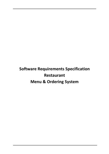
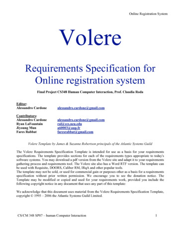
UIUser Interface.Table 1.3.1 Definitions, Acronyms and Abbreviations1.4OrganizationThe remaining document will describe more about the system itself starting fromoverall description of the system. Section 2 will describe the system inducing productperspective, product functions and user characteristics. In this section, it will give theoverall idea of the system. In section 3, it will describe the specific requirements for theSCC. In this it will include all the requirements that are necessary to develop the system.Section 4 will give detailed information about the system design using UML diagrams. In thissection, user scenarios will be used to help describe the system design in detail. The followingsection will be used to describe the prototype SCC system. In this section, there will be detailedinformation of how the system will look like and what user needs to do to test the system. In thelast section, it shows all the references as well as the website for team contact.2Overall DescriptionThis section covers the definition of the SCC system including context for its creation and acomplete description of the system. It provides a sufficient background to understand the specificrequirements described in section 3. The major functions of the SCC are provided along withuser characteristics, project constraints, assumptions, dependencies, and requirements outside thescope of the development project.2.1Product PerspectiveThe context for the SCC is to provide a vehicle with a safe automated response to externalobjects while cruise control is enabled and avoid possible accidents while cruise control isenabled or not. The SCC will operate as part of an embedded vehicle system. It will receiveinformation about current speed and detected objects from the vehicle sensors and remotesystems. It will then use this information along with user settings for set speed and followdistance to provide throttle and brake commands as appropriate to match the user settings.The following block diagram (Figure 2.1) shows how the SCC system fits within the embeddedvehicle system. The SCC system controller is connected to the Vehicle Controller so it canreceive commands from the UI and send alerts to the driver. The SCC System Controller willreceive data inputs from the Sensor System, send brake commands to the Brake Control System,3
and send throttle commands to the Throttle Control System. The subsystems of the SCC will usethe data received by the SCC system controller to calculate the required throttle and brakecommands. These commands will then be sent to the SCC System Controller for prioritizationand propagation to the Throttle or Brake Control Systems.Figure 2.1 Block DiagramThe SCC system itself is made up of three subsystems that fit the following way. The SimpleCruise subsystem is always present and can be enabled or disabled by the user. The FollowingDistance Management subsystem is an optional system that extends the functionality of thesimple cruise system. Following Distance Management is enabled and disabled along with thesimple cruise system. The Automatic Emergency Brake subsystem is another optional systemthat operates independently of the Simple Cruise and Following Distance Management systems.The Simple Cruise feature is constrained to a speed greater than 25 mph. The Following DistanceManagement feature can be enabled along with the Simple Cruise feature but cannot be enabledwithout it. The AEB system cannot be disabled and is enabled regardless if Simple Cruise orFollowing Distance Management features are enabled.2.2Product FunctionsSimple Cruise Driver enables the feature and sets a cruise speed to be maintained. Set speed must begreater than 25 mph. Vehicle maintains the set speed through throttle control and vehicle speed sensorfeedback. Driver may exceed the set speed through direct throttle inputs. Driver may suspend the feature through a button press or by depressing the brake pedal.4
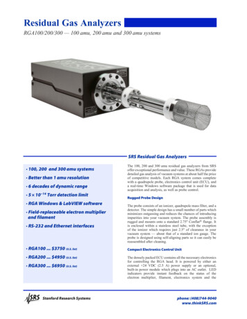
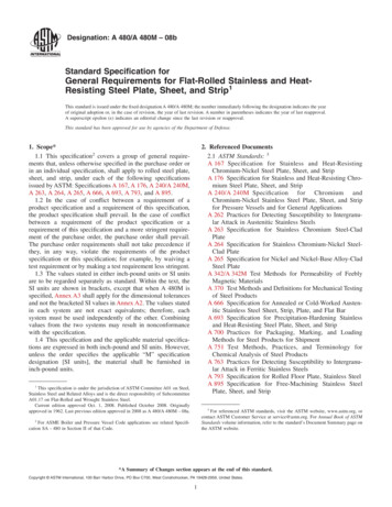
Drive may resume the previously set speed by a button press, and the vehicle mustaccelerate or decelerate at a safe rate to the set speed. Driver may increase/decrease the set speed while active, through button presses. Drive may turn the feature off, which clears the previous set speed.Following Distance Management Driver may set a following distance from a leading vehicle through button controls.Distance is represented to the driver in 4 relative steps (i.e. small up to large) withoutunits, and is maintained internally by the cruise controller as a measurement of minimumtime to intercept, based on the position and relative speed of the leading vehicle. Vehicle maintains maximum possible safe speed through throttle and brake control.Maximum safe speed is calculated with real-time inputs from vehicle speed and leadvehicle tracking information from camera and radar, within the constraints of set speed,minimum following distance/time, and driver throttle input. Alerts the driver in case of emergency.Automatic Emergency Brake Applies maximum braking pressure to minimize stopping distance, if the driver cannotreact in time or with sufficient force.The following high-level goal diagram (Figure 2.2.1) shows a user’s goals when interacting withthe SCC system. Those goals are broken down into use cases based on the features describedabove and the specific requirements described in section 3.Figure 2.2.1 Goal Diagram5
A driver interacting with the SCC system would like to drive their vehicle safely, but withminimal inputs on their part. To achieve this goal the user has three sub-goals: maintain speed,maintain following distance, and retain ultimate control of the vehicle. The first two sub-goals,maintain speed and maintain following distance, are the Simple Cruise and Following DistanceManagement functions described above. The last sub-goal, retain ultimate control of the vehicle,is to allow the driver to react freely as they deem necessary without the system getting in theway.2.3User CharacteristicsThe user of this system will be a driver of a wide range of vehicles. Users can range greatly inexperience from those just learning to drive to professional drivers. Many users may beinexperienced with complex software systems. Users will not be visually impaired and should bephysically able to actuate buttons. Users of this system will consider their use of the system asecondary activity, where the primary activity is driving, and will not give all of their attention tothe use of the system.2.4ConstraintsThe Simple Cruise and Following Distance Management functions will only operate above 25mph. The AEB system will always be operational. In order to ensure the safety of the driver, thesystem needs to properly prioritize throttle commands between the AEB system, user input, andthe cruise system. As well, the system will need to continue to function in the event of wirelessnetwork disruption. The system must not allow remote throttle and brake commands.Development of the system must follow all automotive regulatory policies. The development ofthe system must also produce a product that is externally testable, easily debuggable, andextensible for future product additions.2.5Assumptions and DependenciesThis document assumes that the SCC system will have access to vehicle speed and objectdetection sensors. It also assumes that the embedded vehicle system will provide throttle andbrake control systems that the SCC system can provide commands to. The environment in whichthe SCC system will operate is assumed to be in ideal condition with limited precipitation andwell-paved roads. The SCC system depends upon the vehicle system controller to provide inputsfrom the user.6
2.6Apportioning of RequirementsThe current scope of requirements includes only the SCC system interface and three modularsubsystems: Simple Cruise, Following Distance Management, and Automatic Emergency Brake.Future extensions to the project scope may include the capabilities of: curve speed assist,DSRC-based platooning, DSRC- based traffic signal awareness (SPaT), and pedestrian detection.Each of these functionalities would be extended from the original SCC system, as it would beused as a base. These extensions would provide even a larger range of safety measures for thedriver and others on the road.3Specific RequirementsThe following are some of the major specific requirements of the SCC system. The requirementslisted reflect the behavior of the system.1. The SCC system will maintain and monitor the vehicles speed, set by the user andoptionally adjust the speed based on a user set following distance.2. There will be a default following distance set as soon as the user enables/activates thesystem.2.1. The factory default will be set to a following distance of time length 3.0seconds.2.2. The user will be able to change the set default following distance for theSCC system.3. The following distance in the SCC system will be computed in seconds behind theposition of the Lead Vehicle.4. The driver will have access to buttons to enable/activate the SCC system and control theset cruise speed while the SCC system is active.5. The driver will have access to buttons to set and change the following distance when theSCC system is active.6. The driver will have access to buttons to suspend and resume the SCC system.6.1. The system will stop maintaining the set cruise speed and follow distancewhen suspended.6.2. The system will maintain the previously set cruise speed and followdistance when resumed.7. If the Lead Vehicle decreases speed while FDM is active, the SCC system will reduce theuser vehicle’s speed to maintain the set following distance unless otherwise changed bythe user.7
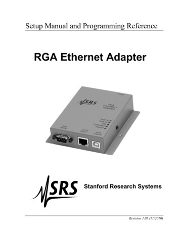
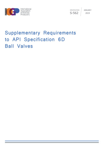
8. If the Lead Vehicle increases speed while FDM is active, the SCC system will increasethe user vehicle’s speed if the set cruise speed permits it.8.1. If the Lead Vehicle continues to speed up and passes the set cruise speedby the user, the user’s vehicle will keep its speed at the set speed.9. The SCC system will maintain the following distance without exceeding the cruise speedset by the user whenever a front vehicle is detected.10. The system will have set following distances available to the user that allows the vehicleto reduce speed and come to a halt if the Lead Vehicle does so, as well.11. The system’s automatic emergency braking system will work whenever the systemsenses a Lead Vehicle getting too close to the user vehicle at a set speed range.12. The system will work alongside and not interfere with other systems present in thevehicle.13. The driver has the ability to override or disable the SCC system at any time. If the driverpressed the brake in the vehicle, the SCC system will disable and begin to slow down thevehicle unless the user presses the gas pedal. The driver can press the gas pedal toincrease the speed while the SCC system is active, but if the speed is not set again, oncethe driver stops pressing the gas pedal the vehicle will slow down to the speed that wasoriginally set by the user.14. Any component of the system that becomes dysfunctional or fails will alert the user thatthe system should be checked and will not continue working until checked and repaired.14.1. If the user attempts to activate the system while is is damaged, it will alertthe driver on the dashboard that the system is not functioning.15. The user will be notified that the system is activated/deactivated through the UI.15.1. The set speed and set distance will also be displayed in the UI while SC orFDM are active.4Modeling RequirementsThis section of the document further represents how the system will behave in the real world.Different visual diagrams will show different views of the system and putting all the thingstogether will give users a clear visual of the system. This section also talks about how the systemwill react on different stages in some of the given scenarios.The following use case diagram (Figure 4.1) describes the user’s interactions with the system aswell as additional external systems that are required for the operation of the SCC system. Thedriver is the primary actor and will initiate all functions related to cruise control and followingdistance management. The throttle control system and brake control system are secondary actorsthat receive speed up or slow down commands from the SCC system. The driver is able to enable8
and disable the system, set a cruise speed, increase or decrease the set speed, suspend and resumecruise, set follow distance, and override the set speed with the throttle.Figure 4.1 Use Case DiagramThe following are extended text descriptions of the use cases seen above in Figure 4.1.Use Case:Actors:Type:Description:Cross Ref.:Use-Cases:Throttle OverrideDriver (initiator)Primary and essentialThe driver manually increases the throttle to override the set cruise speed.The system will continuously send speed up to the throttle control systemwhile the user is still increasing the throttle.Requirement 13Speed UpUse Case:Actors:Type:Resume CruiseDriver (initiator)Primary and essential9
Description: If the system has been suspended, the driver resumes cruise at the same setspeed and follow distance as before the system was suspended. Thesystem will initialize maintaining the set speed.Cross Ref.: Requirement 6Use-Cases: Maintain Set SpeedUse Case:Actors:Type:Description:Cross Ref.:Use-Cases:Increase/Decrease Set SpeedDriver (initiator)Primary and essentialThe driver adjusts the set cruise speed up or down. The system adjustsMaintain Set Speed to use the new cruise speed.Requirement 4Maintain Set SpeedUse Case:Actors:Type:Description:Cross Ref.:EnableDriver (initiator)Primary and essentialThe driver turns on the SCC system.Requirement 4Use Case:Actors:Type:Description:Cross Ref.:DisableDriver (initiator)Primary and essentialThe driver turns off the SCC system.Requirement 4Use Case:Actors:Type:Description:Set SpeedDriver (initiator)Primary and essentialThe driver sets the cruise speed to the vehicles current speed. The systeminitializes or adjusts Maintain Set Speed for the new set cruise speed.Requirement 4Maintain Set SpeedCross Ref.:Use-Cases:Use Case:Actors:Type:Description:Suspend CruiseDriver (initiator)Primary and essentialThe driver suspends the cruise functionality. The system will no longermaintain set speed or follow distance.10
Cross Ref.:Requirement 6Use Case:Actors:Type:Description:Set Follow DistanceDriver (initiator)Primary and essentialThe driver selects one of four follow distance settings. The systeminitializes or adjusts Maintain Set Distance for the new set distance.Requirement 5Maintain Set DistanceCross Ref.:Use-Cases:Use Case:Actors:Type:Description:Cross Ref.:Use-Cases:Use Case:Actors:Type:Description:Cross Ref.:Use-Cases:Use Case:Actors:Type:Description:Maintain Set SpeedSystem (initiator)Secondary and essentialSystem sends Speed Up commands to the throttle control system when thecurrent vehicle speed is lower than the set cruise speed. The system sendsSlow Down commands when the current vehicle speed is higher than theset cruise speed. If there is a set follow distance, the system will MaintainSet Distance before maintaining set speed.Requirement 1Speed Up, Slow Down, Maintain Set DistanceMaintain Set DistanceSystem (initiator)Secondary and essentialSystem sends Slow Down commands when the current follow distance isless than the set follow distance. The system sends Speed Up commandswhen the current follow distance is greater than the set follow distance andthe current speed is less than the set cruise speed.Requirements 1, 7, 8, 9Speed Up, Slow DownCross Ref.:Speed UpSystem (initiator), Throttle Control SystemSecondary and essentialThe system sends commands to the Throttle Control System to speed up acertain amount.Requirements 1, 12Use Case:Slow Do
Software Requirements Specification (SRS) Project SCC - Group 1 . The SCC software system will provide a user with an . 1.4 O rga ni z a t i on The remaining document will describe more about the system itself sta