Transcription
OPERATIONMAINTENANCEANDPARTS MANUALS
1. FEATURES OF THIS MACHINE All functions and mechanisms are controlled Each model is available as stand alone, link A pulse motor conducts all reel rotation and I ndividual models can be used on the same linkprogressive, or individual progressive.by a microprocessor (CPU).stoppage - stop position is controlled by random logic signals.progressive. Progressive - Non-Progressive is dip switchable. All check functions are automatically performed. Useful functions, such as error code display, self-test and meter reading, are incorporated for user's convenience. Various dip switch setting for partial pays are Mechanical elements in the driving section have Each machine is equipped with a two wireavailable.female plug ready to plug into any one of threemanufacturers' progressive controllers withoutmodification to the Universal Slot Machine.been significantly reduced to both minimizewear and to ensure long life. A photo sensor conducts all coin identification. I ndividual bright light displays are available. Total internal unitization enables each unit, Tower light unit and sound PROMs are in-such as a hopper unit, a reel unit, a logic board,a power supply unit, etc., to be simply installedand removed.cluded in machine price. Models are available as credit or non-credit. All parts being used in this machine are of the Outputs for on-line computer systems arehighest quality and due consideration has beengiven to their layout and configuration.available as an option. The Universal Slot Machine is supported byone year warranty. The Universal Slot Machine has 32 stop capability.-1-
2. OPERATION AND MAINTENANCEA. INSTALLATION1.B. BEFORE APPLYING POWER FORTHE FIRST TIMEI nstall on a flat surface.2. This machine is designed for indoor installation, it should not be installed anywhere outdoors.3. Avoid locations subjected to direct sunlight,high temperature/humidity, violent vibrations, dust, etc. Also avoid locations wheredangerous objects or fire-fighting apparatusare stored - be sure not to block an emergency exit.4.I n order to prevent any troubles occurringduring play, be sure to fix the machine ontothe slot stand with 4 bolts as shown in Fig. 1.1. Check for damage caused by mishandlingduring shipment.2.3.Make sure that all connectors, and similardevices are not disconnected.Make sure that all reels are spinning properly.4. The grounding terminal provided on themachine should be connected to "earth"without exception.C. HOW TO OPERATE1. When the machine is switched on, it will testitself and any malfunctions will be indicatedto the attendant on the "ERROR" code; referto the "ERROR" code clause for an explanation.2.Make sure the machine is well ventilated, ifthe temperature of the IC and transistor isover 60 C, performance cannot be guaranteed.3. Whenever connecting the solid-state modulepower cord to, or disconnecting it from, theoutlet, be sure to turn the power off.4. Be sure to use rated fuses.Note:After installing the machine, removethe two shipping screws that fix thehopper unit on the cabinet floor.- 2-
3.D. BEFORE DETERMINING WHETHERTHERE IS A'REAL' MALFUNCTION,PLEASE READ BELOW1. The slot machine is broadly divided into fiveelectrical component sections; the power unit,the main logic board, the reel unit, the handleunit and the hopper unit. These are wired together and if any of them malfunctions, theslot machine as a whole will not work normally.4. If a normal image does not appear when turni ng the machine "ON", try "SELF-TESTPROGRAM".5.When you think that there is somethingwrong, check all five sections for minor easyto remedy disorders - these may be correctedeither on the spot or with a modicum of repair work.Even if the solid-state module seems to be outof order, do not check the circuits with a circuit tester, or similar device since the internalvoltage of the testing may sometimes destroythe IC.6. Be sure all socketed IC's are properly seatedi n their sockets. Applying power with an ICi nstalled backwards may destroy it along withother related circuits.I f the checked section seems normal, testother related parts, too.Note:Is the plug securely plugged in? Isn't it disconnected? Make sure to check for proper contact and that power is "OFF" before pluggingor unplugging the unit.Although Universal products are manufacturedwith the utmost care they may malfunction whenused for long periods. Therefore the machineowner or manager should check the condition ofthe machine daily.Be sure to use only the fuse indicated!2. Check the fuse: If a fuse also blows, then another part is out of order.- 3-
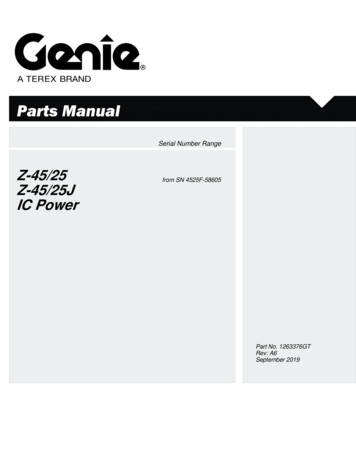
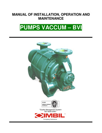
3. SPECIFICATIONSA. ELECTRICAL SPECIFICATIONS1.Power supply100V115V120V220V240V2.Power consumption180W3.FusesACACACACACFig. 3Fig. 2-4-
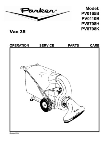
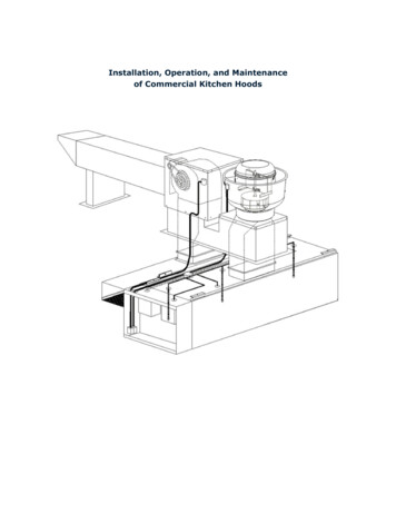
B.a)OVERALL MACHINE DIMENSIONSTYPE "A" WIDE BODY A BALLY type stand can be used with slight modifications, UNIVERSAL has 2" less depth. Custom glass which fits in a BALLY type machine can be installed in a UNIVERSAL slot- minor modification required.- 5-
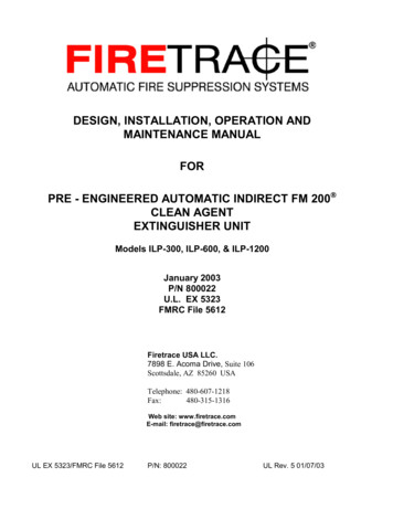
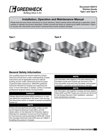
b) TYPE "B" WIDE BODY A BALLY type stand can be used with slight modifications, UNIVERSAL has 2" less depth. Custom glass which fits in a BALLY type machine can be installed in a UNIVERSAL slot- minor modification required.- 6-
* A BALLY type stand can be used with slight modifications, UNIVERSAL has 2" less depth.* Custom glass which fits in a BALLY type machine can be installed in a UNIVERSAL slot- minor modification required.- 7-
4. NOMENCLATURE OF EACH PARTA. OUTSIDE- 8-
B. INSIDE- 9-
C. P.C.B. MOUNTING POSITIONS-1o-
5. MACHINE FUNCTIONSA. SWITCH POSITIONS AND NAMESa)OUTSIDE- 11 -
B. DESCRIPTIONS OF SWITCHESThe following numbers and descriptions correspond to Fig. 10 and 11. RESET SWITCHThe "RESET SWITCH" is used to reset agame when an error code is indicated and agame is invalid, or to cancel the "SELF-TESTPROGRAM" and to return to a normal game. VOLUME CONTROLLERThe "VOLUME CONTROLLER" is used toadjust the sound volume which this machinewill make.MAIN POWER SWITCH2 DOOR SWITCHThe "DOOR SWITCH" is used to check to seeif the front door is open or not. It is "OFF"when the front door is open. When it is open,the error code "50" is indicated on the "WINNER PAID METER" and the normal gamedoes not work. Please note that the "FRONTDOOR KEY SWITCH" also checks to see ifthe front door is open or not.The "MAIN POWER SWITCH" is used toswitch AC power on or off. HOPPER OVERFLOW CONTROL SWITCH: TEST SWITCHThe "HOPPER OVERFLOW CONTROLSWITCH" is used to select the ways of checki ng the quantity of coins inside the "HOPPERUNIT" or the "CASH BOX".CONTROL BY CONDUCTIONThe checking terminals inside the "HOPPERUNIT" checks the quantity of coins and control the way of the inserted coins, that is, intothe "HOPPER UNIT" or the "CASH BOX".The "TEST SWITCH" is used to place themachine in test modes by pressing the buttonto correspond with the test mode required.( e.g. TEST PORT NO. 4; press the button 4times.)CONTROL BY PROGRAM COIN TEST SWITCHThe "COIN TEST SWITCH" is used to creategame credits for testing and only while thefront door is open. Each time the "COINTEST SWITCH" is pressed, game credits increase. However, there is no actual payoutwhile you are testing games. When you closethe front door, the game credits made byusing this switch are cleared. COIN SWITCHThe "COIN SWITCH" is using two photosensors to count the inserted coins to checkthe time and direction of a coin passingthrough it.- 1 2-I nstead of conductors, the program itselfchecks quantity of coins and controls the wayof inserted coins, that is, into the "HOPPERUNIT" or into the "CASH BOX". The microprocessor memorizes the quantity of coinsand determines the remaining quantity ofcoins by calculating.JACKPOT RESET KEY SWITCH/PASSINGTIME ADJUSTMENT SWITCHJACKPOT RESET KEY SWITCHThis key is used to clear the status of "JACKPOT/TILT" in case of the "DOLLAR VERSION" (Refer to the clause of "AUTOMATI C HOPPER PAYOUT" and "JACKPOTRESET".).
PASSING TIME ADJUSTMENT SWITCHThis key is also used to adjust the time limitation for a coin to pass through the "COINSWITCH". You can adjust the maximum timeand the minimum time by turning this switchi n counter clock wise and in clock wise respectively. Please note that this adjustment isavailable only during the "TEST PORT NO.3" of the "SELF-TEST PROGRAM".11 CHANGE BUTTON SWITCH10 METER READING KEY SWITCHThe "CHANGE BUTTON SWITCH" is located on the front door and used when a player needs an attendant's help while playing amachine. When you press the "CHANGEBUTTON SWITCH" for an attendant's helpone time, the "TILT" lamp on the tower lighti s turned on. If you press the "CHANGEBUTTON SWITCH" again, the light. can beturned off.COINS TO CASH BOX SWITCHThe "COIN TO CASH BOX SWITCH" isusing one photo sensor to count the coinsbeing overflowed into the "CASH BOX".DIP SWITCHESThe "DIP SWITCHES" are not shown inFig. 11 but are located on the "MAIN LOGICBOARD". These switches are used to selectthe following functions.- 1 3-
6. ERROR CODEIf malfunctions mentioned below happen, thefollowing error codes are indicated on the "WINNER PAID METER". At the same time, the"TILT" lamps on the reel glass and the towerlight (except in case of the error code "50") areturned on, the error sound is activated and thegame becomes invalid."MAIN LOGIC BOARD" and at the sametime, switch on AC power. Please note thatyou have to keep pressing the "ALL CLEARSWITCH" at least 2 or 3 seconds even afterswitching on AC power. Through the aboveprocedures, the "TILT" lamps and the errorsound can be turned off. Also the error code"12" can be cleared and the game becomesavailable.1) LOW VOLTAGE "11"If voltage temporarily drops, the error code"11" is indicated on the "WINNER PAIDMETER", the "TILT" lamps are turned on,the error sound is activated and the gamebecomes invalid. However, when voltagerecovers to the rated minimum, the machineis automatically reset within 2 seconds andthe game becomes valid. Please note that thedisplay of the error code "11" still remainson the "WINNER PAID METER" even afterthe machine is automatically reset. It will becleared when a next game is played.3) COIN JAM "21"2) BATTERY POLARITY "12"If the voltage of the built-in battery is lowerthan the rated one when AC power is "ON",the error code "12" is indicated on the "WINNER PAID METER", the "TILT" lamps areturned on, the error sound is activated andthe game becomes invalid. In such a case, thebuilt-in "RAM" has not memorized the previous status. Therefore, it is necessary to completely clear the "RAM" memory. Press the"ALL CLEAR SWITCH" being located on the- 1 4-I f it takes more or less than the time beingfixed for a coin to pass through the "COINSWITCH", a coin passes the "COIN SWITCH"from down to up, or some coins are jammedat the "COIN SWITCH", the error code "21"is indicated on the "WINNER PAID METER", the "TILT" lamps are turned on andthe error sound is activated. The "COINSWITCH" is using two photo sensors, whichnot only count the inserted coins but alsoprotect a machine against "STRINGING".Press the "RESET SWITCH" to clear all theabove. If coins are jammed around the "COINSWITCH", remove them before pressing the"RESET SWITCH".
4) COINS BEING OVER-DISPENSED "31"I f the "HOPPER UNIT" pays out more coinsthan the coins being won or pays out coinsexcept when they are won, the error code"31" and the numbers of coins being overdispensed are indicated on the "WINNERPAID METER", the "TILT" lamps are turnedon and the error sound is activated. Duringthis status, the game is invalid. In such a case,press the "RESET SWITCH" to clear thestatus of the error code - 31". Please notethat the numbers of coins being over-dispensed are totaled to the "METER READI NG NO. 3 (TOTAL OUT)" and the "METERREADING NO. 9 (OVER PAID)".5) HOPPER JAM "32"I f the "HOPPER PAYOUT COUNT SWITCH"i s switched on for 2. or 3 seconds by someobstructions like coins being jammed in it, theerror code "32" is indicated on the "WINNER PAID METER", the "TILT" lamps areturned on and the error sound is activated. Ifthis happens, press the "RESET SWITCH" toclear the status of the error code "32" afterremoving such obstructions.not spin, the error code "41" is indicated onthe "WINNER PAID METER", the "TILT"lamps are turned on and the error sound isactivated. In such a case, the status at thetime when the error happens is maintaineduntil the status of the error code "41" iscleared by pressing the "RESET SWITCH".Please note that the reel spinning soundchanges to the error sound 15 seconds afterthe said error happens, and also that the gamebeing in progress at the time when the saiderror happens becomes invalid. Press the"RESET SWITCH" to clear the status of theerror code "41.8) 2ND REEL SPINNING IMPROPERLY "42"I n case the 2nd reel spins improperly or doesnot spin, the error code "42" is indicated onthe "WINNER PAID METER", the "TILT"lamps are turned on and the error sound isactivated. During this status, the game is invalid. (Please refer to the explanation in 7.)9) 3RD REEL SPINNING IMPROPERLY "43"I n case the 3rd reel spins improperly or doesnot spin, the error code "43" is indicated onthe "WINNER PAID METER", the "TILT"lamps are turned on and the error sound isactivated. During this status, the game is invalid. (Please refer to the explanation in 7.)6) HOPPER EMPTY "33"I f coins are not paid out within 9 to 10seconds after the "HOPPER UNIT" startsrunning, the error code "33" is indicated onthe "WINNER PAID METER", the "TILT"lamps are turned on and the error sound isactivated. During this status, the game isinvalid. This error normally happens whenthere are no coins in the "HOPPER UNIT".Therefore, refill the "HOPPER UNIT" withcoins and press the "RESET SWITCH" toclear the status of the error code "33". Thenclose the "FRONT DOOR". The "HOPPERUNIT" starts to pay out the balance.10) DOOR OPEN "50"7) 1ST REEL SPINNING IMPROPERLY "41"I n case the 1st reel spins improperly or does- 1 5-I n case the front door is open, the error code"50" is indicated on the "WINNER PAIDMETER", the "DOOR OPEN" lamp (yellowcolor) on the tower light unit is turned on andthe error sound is activated every 2 minutes.During this status, the game is invalid butcan be tested by using the "COIN TESTSWITCH". The "DOOR OPEN" lamp and theerror sound can be turned off by closing anclocking the front door. However, the errorcode "50" still remains on the "WINNEFPAID METER" even after the front door itclosed and locked and can be cleared onh
when a next game is played. Please note thatthe insertion of coins during this error is thesame as using the "COIN TEST SWITCH" andi s not added to the "TOTAL IN COUNTER".Also there is no actual payout even thoughyou win.- 1 6-Note:The "SELF-TEST PROGRAM" willnot work even though the aboveerrors are cleared, unless the game iscompletely over.
7. SELF-TEST PROGRAMUpon opening the front door, the - "TESTSWITCH" will be found nn the right side of thecabinet. Any of the following mentioned eighttests can be selected according to the times the"TEST SWITCH" is pressed. The "TEST PORTNO." is indicated nn the most right of the "WINNER PAID METER", so simply press the "TESTSWITCH" until you get the desired test. If youpress the "TEST SWITCH" again after the "TESTPORT NO. 8", it returns to the "TEST PORTNO. 1". Once you select one of the followingtests, it will be fixed 1 or 2 seconds after you stoppressing the "TEST SWITCH" and then the indication of the fixed "TEST PORT NO." movesfrom the right to the most left of the "W I N N E RPAID METER". Now, the test is ready. Pleasenote that, even after a selected test is fixed, it iscancelled if the "TEST SWITCH" is pressed again.In such a case, the test port returns the "TESTPORT NO. 1". When you want to cancel the"SELF-TEST PROGRAM" after testing, justpress the "RESET SWITCH". In case of testingthe "TEST PORT NO. 2, 5, 7 or 8", to closethe front door will automatically cancel the"SELF-TEST PROGRAM".repeated as many times as desired, unless thistest port is cancelled by pressing the "RESETSWITCH".Note: The "SELF-TEST PROGRAM" worksonly when the front door is open and theerror code "50" is indicated nn the "WINNER PAID METER". It does not workwhen a jackpot has been won or a gameis in process.1) SYMBOL DETECTION TEST "TEST PORTNO. 1"Note: In case a reel spins improperly, thesymbols will not registered and thecode "0" is indicated together withthe error code.2) REEL SET TEST "TEST PORT NO. 2"After this test port is fixed and the front dooris closed, the number "1" is indicated nn the"COINS PLAYED METER" which meansyou have one playing credit to start the reels.I n this test port, it is tested if each symbolnn the reels is correctly detected or not, andthe code numbers of symbols nn the centerwin line are indicated nn the "WINNER PAIDMETER" when the reels stop spinning. Pullthe handle lever to test it, referring to Appendix A. During this test port, the test can be- 1 7-This test port determines whether each refstops nn the center win line in order c"STOP POSITION" and whether the refstrips correspond to the program. There at22 stops nn each reel and each reel symbolhas its own "SYMBOL CODE NO." as mertinned i n the "TEST PORT NO. 1". Wheyou test this test port, each reel autnmaticallstarts and stops spinning in order of "STOPPOSITION". When each reel stops spinningthe "SYMBOL CODE NO." is indicated cthe "WINNER PAID METER". Please nn -
that this test repeats same unless cancelled byclosing and locking the front door or pressingthe "RESET SWITCH".Note:The "STOP POSITION NO." is from"21" to "0".Note:When the above mentioned test goesto the "STOP POSITION NO. 0", itstarts the same from the "STOP POSI-TION NO. 21" repeatedly unless cancelled.3)COIN SWITCH TEST "TEST PORT NO. 3"After this test is fixed, close the front door.I n this test, the time when it takes for a cointo pass through the "COIN SWITCH" ismeasured and is indicated on the "WINNERPAID METER". Please note that the indica-tion is done in a milli-second unit.- 1 8-
Note: If it takes over 1 second for a coin topass through the "COIN SWITCH"even while testing, the error code"21" will be indicated on the "WINNER PAID METER". Please neverforget to push the "RESET SWITCH"after this test port is finished.ADJUSTMENT OF TIME LIMITATION FORTHE PASSING OF A COINAlso during this test port, a time limitationadjustment can be made for the passing of acoin by the following procedures.a) THE MAXIMUM TIME FOR A COIN TOPASS:The maximum time for a coin to pass isadjustable from 60 to 500 milli-seconds.Turn the "PASSING TIME ADJUSTMENT SWITCH" in counter clock wise.One turn is 20 milli-seconds. The adjustedti me for a coin to pass is indicated on themost right of the "WINNER PAID METER".b) THE MINIMUM TIME FOR A COIN TOPASS:The minimum time for a coin to pass isadjustable from 0 to 50 milli-seconds.Turn the "PASSING TIME ADJUSTMENT SWITCH" in clock wise. The adjusted time for a coin to pass is indicatedon the "COINS PLAYED METER".When you complete the above mentioned adj ustments, fix them by inserting a coin orcancelling this test port.Note: The time it takes for a coin to pass isautomatically adjusted at the normaltime limitation, minimum of 0 millisecond and maximum of 2,000 milliseconds, unless it is manually adjusted.- 1 9-
4) HOPPER TEST "TEST PORT NO. 4"This test port determines if the "HOPPERUNIT" is working correctly or not. The"HOPPER UNIT" automatically pays out 10coins 2 seconds after this test port is fixed,and the number of those paid-out coins (10)i s indicated on the most right of the "WINNER PAID METER". If there is an errorwhen coins are paid out, the error code is indicated on the "WINNER PAID METER".Please note that those paid-out coins are notcounted into the "TOTAL OUT COUNTER".However, those coins which are paid outduring this test port are counted in the "METER READING PROGRAM". Therefore, ifyou want to know how
3. SPECIFICATIONS A. ELECTRICAL SPECIFICATIONS 1. Power supply 100V AC 115V AC 120V AC 220V AC 24