Transcription
LP Gas (Propane) Conversion InstructionsDANGERAsphyxiation Hazard. These instructions include a procedure for adjusting the air-fuel mixture on thisboiler. Always use a combustion analyzer to measure the CO2 (or Oxygen) and Carbon Monoxide (CO) levelsin flue gas. Adjusting the air-fuel mixture without a proper combustion analyzer will result in unreliableboiler operation, personal injury, or death due to carbon monoxide poisoning.Explosion Hazard, Electrical Shock Hazard, Burn Hazard. The gas supply shall be shut off prior todisconnecting the electrical power, before proceeding with the conversion.WARNINGThis conversion kit shall be installed by a qualified service agency in accordance with the manufacturer’sinstructions and all applicable codes and requirements of the authority having jurisdiction. If theinformation in these instructions is not followed exactly, a fire, an explosion or production of carbonmonoxide may result causing property damage, personal injury, or loss of life. The qualified serviceagency is responsible for proper installation of this kit. The installation is not proper and complete until theoperation of the converted appliance is checked as specified in the manufacturer’s instructions suppliedwith the kit.These instructions are intended for use only with sizes listed in this document.Consult Appendix A in Installation, Operating and Service ( I, O & S) Instructions for installations above2,000 ft. I, O & S Instructions are supplied with boiler and available on manufacturer's website.These instructions are included in LP conversion kits listed in Table 1:Table 1: LP Conversion KitsSizeLP Conversion 1270107938-01320108015-01*399108015-02** Also used for LP Service kitPage2-32-32-32-3455Required Tools/Equipment:Parts Included with This Kit: 15/16" Wrench (Flare Fitting) LP Venturi 1-1/8" Wrench (Gas Flex Line) Hardware Torx T-25 (Gas Valve to Venturi) Blower O-ring Torx T-30 (Venturi Assembly to Blower) Gas Valve Coupling Phillips Head Screwdriver Rating Label Flat Head Screwdriver/ 5/16" Nut Driver Service Label 7mm Hex Head Socket (Venturi Assembly toBlower 320/399) 1-7/16" Wrench (Gas Valve Adaptor 320/399) Combustion Analyzer107958-01 - 8/171
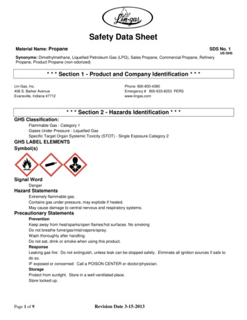
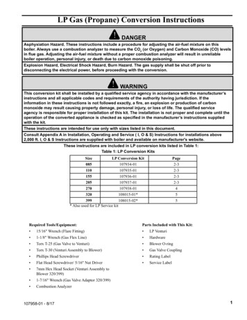
To convert this boiler for use on LP gas, perform the following steps:1. If not already done, install the boiler in accordance with the Installation, Operating, and Service instructions, followingall instructions in Section XI “Start-up and Check-out” up to Step 10.2. Disconnect power supply to boiler3. Shut off gas supply to boilerSteps 4 thru 12 for boiler sizes 85, 110, 155 and 205 (Figure 3)Disconnect tube to air proving switch and disconnect harness from rectifier module on gas valve. (Figure 8)Use wrench and back up wrench to disconnect flexible gas pipe from gas valve at flare fitting (Figure 2).Remove (2) screws connecting gas valve to venturi assembly. (Figure 3)Remove (3) screws connecting venturi assembly to blower. (Figure 3)Replace natural gas venturi assembly with propane (LP) venturi assembly, ensuring o-ring between blower and venturiassembly is in place and arrow on venturi points up. (Figure 3)9. Secure venturi assembly to blower using (3) screws removed in step 7.10. Ensure coupling between venturi assembly and gas valve is in place and secure using (2) screws removed in step 6.11. Re-connect flexible gas pipe to gas valve.12. Re-connect tube to air proving switch and reconnect harness to rectifier module on gas valve.4.5.6.7.8.When disconnecting flexible gasline, place backup wrench on thisnut to prevent damage to gas valve.ConnectionFlexible Gas LineFigure 2: Backup Wrench Detail2107958-01 - 8/17
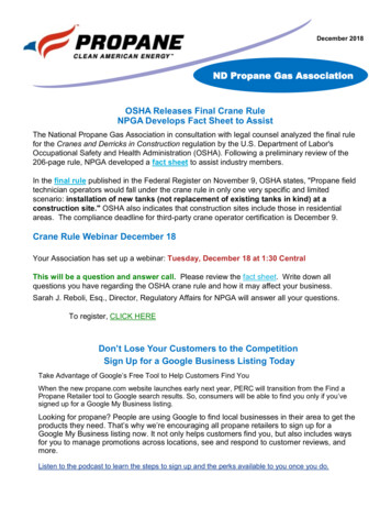
Steps 13 thru 14 for boiler size 110 installations above 2,000ft only (Figure 3 and 4)13. Attach PVC attenuator to venturi assembly. (Figure 3)14. Insert perforated attenuator into vent adaptor (Figure 4) and skip to step 27.O-RingArrow to Point upVenturi AssemblyTighten ClampCouplingPVC Attenuator Assembly(Used on Size 110 InstallationsAbove 2,000 ft. only)Figure 3: 085-205 Blower/Gas Valve/Venturi DetailPerforated Attenuator(Used on Size 110 LPInstallations Above 2,000 ft. only)Vent Adapter107958-01 - 8/17Figure 4: Vent Attenuator for 110 LP Installations above 2,000ft.3
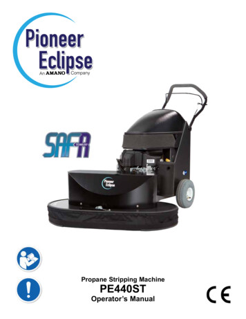
Steps 15 thru 21 for boiler size 270 (Figure 5)15. Remove attenuator from venturi assembly, disconnect tube to air proving switch, and disconnect harness from rectifiermodule on gas valve. (Figure 9)16. Use wrench and back up wrench to disconnect flexible gas pipe from gas valve at flare fitting (Figure 2).17. Remove (3) screws connecting gas valve to venturi assembly. (Figure 5)18. Remove gasket from gas valve outlet, insert factory supplied orifice into groove of gasket and replace. (Figure 5)19. Secure gas valve to venturi assembly using (3) screws removed in step 17.20. Re-connect flexible gas pipe to gas valve.21. Re-attach attenuator to venturi assembly. Re-connect tube to air proving switch, reconnect harness to rectifier module ongas valve and skip to step atorFigure 5: 270 Blower/Gas Valve/Venturi Detail4107958-01 - 8/17
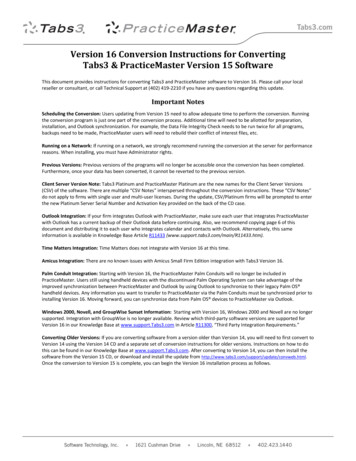
Steps 22 thru 26 for boiler sizes 320 and 399 (Figure 6)22. Loosen union between gas valve and venturi assembly23. Remove (3) screws connecting venturi assembly to blower.24. Replace natural gas venturi assembly with propane (LP) venturi assembly, or replace propane (LP) venturi assembly,ensuring o-ring between blower and venturi assembly is in place and arrow on venturi points up.25. Secure venturi assembly to blower using (3) screws removed in step 23.26. Tighten union between gas valve and venturi assembly, and ensure gasket is between gas valve adaptor and venturi. Gasvalve is oriented as shown in Figure 6.O-RingVenturi AssemblyArrow to point upGasketGas Valve AdapterFigure 6: 320-399 Blower / Gas Valve / Venturi Detail107958-01 - 8/175
27. Before attempting to start the boiler, turn the throttle (Figure 8 and 9) clockwise until it stops (several full turns).28. Turn throttle counter-clockwise the exact number of turns shown in Table 7.WARNINGThe throttle adjustments shown in Table 7 are approximate. The final throttle setting must be foundusing a combustion analyzer. Leaving the boiler in operation with a CO level in excess of 200PPM airfree could result in injury or death from carbon monoxide poisoning.Table 7: Starting Number of Throttle Turns for Conversion to LP se Turns(From Fully Closed)10.010.09.014.03.54.05.0Main Flow ThrottleOutlet TapInlet TapTube to AirProving SwitchGas InletGas OutletServo Regulator(OFFSET Adjustment)Rectifier ModuleFigure 8: 085-205 Gas Valve DetailOutlet TapInlet TapTube to AirProving SwitchGas InletGas OutletMain Flow ThrottleServo Regulator(OFFSET Adjustment)Rectifier Module6Figure 9: 270-399 Gas Valve Detail107958-01 - 8/17
WARNINGAll combustion performance numbers MUST be verified with a combustion analyzer. Failure to do so couldresult in substantial property damage, severe personal injury or death.29. Select the correct boiler size, altitude, and fuel using the touch screen display.a.Check boiler's rating label for actual boiler size.b.Confirm installation altitude.c.Press "Adjust" button on the Home screen.d.Press "Adjust" button on the Adjust Mode screen.e.Press "Login" button to access Password screen.f.Press 5-digit display to open a keypad. Enter the password "86" and press the return arrow to close keypad.Press "Save" button.g.Press "Adjust" button to enter Adjustment Mode.h.Press "Modulation Setup" menu button.i.Press "Adjust" button after reading Warning screen.j.Use the arrow buttons to select the correct size, altitude, and fuel of your boiler. Press the (Check withCircle) button to enter your selection.k.Press "Enter" button until display stops blinking, press next and repeat until "Completed" is displayed.l.Press X to exit.m.Press "Confirm" to verify correct size, altitude, and fuel is displayed.30. Attempt to start the boiler using the operating instructions located on inside of boiler front door. If the boiler does notlight on the first try for ignition, allow boiler to make at least four more attempts to light. If boiler still does not light,turn the throttle counter-clockwise in 1/8 turn increments, allowing the boiler to make at least four tries for ignition ateach setting, until the boiler lights.31. After the burner lights, force the burner to high fire by entering the Adjust Menu and then High Fire Hold as describedin Section XI "Start-up and Checkout" of I, O & S Instructions. Allow the boiler to operate for approximately 5 minutesbefore taking combustion readings. Note: after 10 minutes, the boiler is automatically released from high fire hold.32. Perform a combustion test, sampling flue products from the tap in front of the vent adaptor.33. With burner at high fire, adjust throttle as needed to obtain CO2 (or O2) setting shown in Table 10: To reduce CO2 (increase O2) turn throttle clockwise. To increase CO2 (reduce O2) turn throttle counter clockwise. Make adjustments in increments of 1/8 and 1/4 turns and allow the boiler at least a minute to respond to each adjustmentbefore making another.34. Force burner to low fire by entering the Adjust Menu and then Low Fire hold as described in Section XI "Start-up andCheckout". Allow the boiler to operate for approximately 5 minutes before taking combustion readings.WARNINGAsphyxiation Hazard. Use combustion analyzer for all gas valve adjustments. Low fire offset screw is verysensitive. Adjust offset no more than 1/8 turn before checking combustion with analyzer. Maximum totaloffset adjustment 1 turn. Adjustments greater than 1 turn may damage regulator diaphragm. Failure tofollow these instructions could result in death, serious injury or substantial property damage.35. With burner at low fire, adjust offset regulator as needed to obtain CO2 (or O2) setting shown in Table 10. To reduce CO2 (increase O2) turn offset regulator counter-clockwise. To increase CO2 (reduce O2) turn offset regulator clockwise. Make adjustments in increments no more than 1/8 turns and allow the boiler at least a minute to respond to eachadjustment before making another.107958-01 - 8/177
Table 10: Acceptable Combustion Readings for LP Gas (Propane) OperationAcceptable %CO2 Combustion Readings for LP Gas (Propane)AltitudeSize0-2,000 ft2,001-6,000 ft6,001-7,800 .0-10.510.57,801-10,100 710.49.9-10.210.2Max. COAir FreeCOAFreadingsmust beless than200 ppm*Low Fire Range and Target values are the same as High Fire above. Ensure low fire CO2 reading is less than orequal to high fire CO2 reading.Acceptable %O2 Combustion Readings for LP Gas (Propane)AltitudeSize0-2,000 ft2,001-6,000 ft6,001-7,800 45.45.5-5.1851102705.7-5.05.07,801-10,100 .8-5.45.4Max. COAir FreeCOAFreadingsmust beless than200 ppm**Low Fire Range and Target values are the same as High Fire above. Ensure low fire O2 reading is greater than orequal to high fire O2 reading.Table 11: Minimum and Maximum Inlet PressureSizeMin. (in. wc)Max. (in. wc)85-3998.014.036. Verify gas inlet pressure is between values listed in Table 11 with all gas appliances (including converted boiler) both onand off.37. A sheet of yellow labels is provided in the envelope with these instructions for boilers converted from natural to LP gas.Select the respective firing rate for the boiler being converted from this sheet of labels and apply them as follows: Apply the "Rating Plate Label" adjacent to the rating plate. Apply the "Gas Valve Label" to a conspicuous area on the gas valve. Apply the "Boiler Conversion Label" to a conspicuous surface on, or adjacent to, the outer boiler jacket. Fill in thedate of the conversion and the name and address of the company making the conversion with a permanent marker.38. A label with acceptable LP combustion readings is provided with these instructions. Affix this label in a conspicuouslocation on the boiler.39. Refer to the Section XI " Start-up and Checkout" in the I, O, and S Instructions and perform any checks not alreadycompleted.8107958-01 - 8/17
Size LP Conversion Kit Page 085 107934-01 2-3 110 107935-01 2-3 155 107936-01 2-3 205 107937-01 2-3 270 107938-01 4 320 108015-01* 5 399 108015-02* 5 * Also used for LP Service kit These instructions are included in LP conversion kits listed in Table 1: Table 1: LP Conversion Kits Required Tools/Equipment: 15/16" Wrench (Flare Fitting) 1-1/8" Wrench (Gas Flex Line) Torx T-25 (Gas .