Transcription
LANDMARK ARTICLEFr ontal Cephalometrics:Pr actical Applications, P ar t IRobert M. Ricketts, DDS, MS1/Duane Grummons, DDS, MSD2Aims: Many clinicians have not employed the frontal perspective. Therefore, the purposesof this paper are to: (1) update the findings in morphology and growth in the transversedimension; (2) simplify evaluation of facial asymmetry using the Ricketts and Grummonsfrontal analyses; and (3) describe practical clinical applications of anteroposterior imagesand analysis. Methods: Maxillary width variations, frontal (anteroposterior) anatomic landmark locations, and frontal tracing methods are specified. Asymmetry conditions are differentially treated. Results: Utilizing frontal facial information, therapeutic approaches aremore specific and effective, while directed toward particular etiology. Occlusal plane, midline, chin location, and smile esthetics are primarily addressed. Beautiful facial proportionsand smile harmony are demonstrated. Asymmetry of the facial parts is the rule, rather thanthe exception. Conclusion: Patients view themselves from the frontal perspective, so thiscarries priority in assessing problems and treatment outcomes. Facial harmony and smilebeauty are optimal when facial and dental midlines are aligned. The occlusal plane shouldbe level, or nearly so. The maxillary width should be sufficiently wide to be in harmony withthe individual patient facial type and morphology. The chin should be centered, or nearlyso. Best facial development and proportionality exist when the transverse skeletal and dental components are optimized and symmetric. World J Orthod 2003;4:297–316.n the past, relationships in the sagittal plane havedominated orthodontic thinking to such an extentthat the great majority of clinicians did not evenbother to procure frontal radiographs (images, headplates). However, several factors have awakened thecurrent clinician to a deeper interest in the transverse dimension1: (1) maxillary palatal dysjunctionexpansion (rapid palatal expansion [RPE], rapid maxillary expansion [RME]), with a 100-year history, hasbecome standard teaching in graduate orthodonticprograms; (2) lighter wires, required as bondedbrackets became popular, have been successful formandibular arch lateral expansion (the writings anddemonstrations by Graber, 2 Frankel, 3 and othersthat functional appliance arch widening occurredwith buccal shields, probably stretching the periosteum, further had a profound influence on concepts); (3) a full and stunning smile is recognized toemphasize the transverse perspective4,5; (4) nasalwidth and piriform aperture asymmetries are factorsin frontal esthetics6 (the entire midfacial complexbecame associated with the respiratory system,together with mandibular posturing) 7–9 ; and (5)mandibular and cranial asymmetries have becomesignificant in planning treatment. 10,11 Surgicallyassisted palatal dysjunction (rather than dentalexpansion) was found to be indicated for preservation of the maxillary periodontium12 and to reducerelapse. Deciduous and early mixed dentition treatment for skeletal and functional corrections involvesa 3-dimensional consideration.13,14 Therefore, it istime for a shift in orthodontic thinking regarding thefrontal image and perspective.I1ThisWJO two-part article is the last publication involving Dr Ricketts before his death.2Private Practice of Orthodontics, Spokane, Washington, USA.REPRINT REQUESTS/CORRESPONDENCEDuane Gummons DDS, MSD, 9425 N Nevada, Suite 100,Spokane, WA 99218-1283, USA. E-mail: grummons@aol.com ordgrummons@braceplace.org297COPYRIGHT 2003 BY QUINTESSENCE PUBLISHING CO, INC.PRINTING OF THIS DOCUMENT IS RESTRICTED TO PERSONAL USE ONLY.NO PART OF THIS ARTICLE MAY BE REPRODUCED OR TRANSMITTED IN ANY FORMWITHOUT WRITTEN PERMISSION FROM THE PUBLISHER.
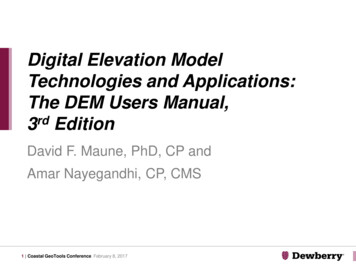
WORLD JOURNAL OF ORTHODONTICSRicketts/GrummonsFig 1 Typical structures traced in the frontal. Tracingpoints include MSR, midsagittal reference (midlinefacial plane); Cg, crista galli; ANS, anterior nasal spine;ME, menton; OP, occlusal plane; J,J’, lateral maxillaeat molars on each side; Ag, gA, antegonial on eachside; Ms, mastoid process; Za-aZ, zygomatic processsuture on each size; Z,Z’, zygomaticofrontal suture; Fr,foramen rotundum; Co, condylion, posterior superioraspect of condylar process; Ra, ramus ascending; SO,superfiscial orbitale; NC, nasal cavity.Fig 2 Frontal landmarks are: frontofacial plane (Z-Ag),line from zygomaticofrontal suture (Z) through theantegonial tubercle (Ag); transverse Frankfort plane(Za-aZ), line through centers of zygomatic arches;nasion-point B (Na-B), line from nasion through pointB; frontal denture plane, line from Ag to J point; frontalmandibular plane, central sagittal plane from crista galliperpendicular to frontal Frankfort plane; frontal maxillary plane, line through two J points; frontal occlusalplane, bisection of first molar occlusion.The time has come for frontal cephalometrics tobe a routine part of each clinician’s practice. Bygrace of the computer, reference points and planeshave been sorted out and time tested. The possibilities with expansion are remarkable, when conductedwith current technological knowledge and science,especially for the younger patient. When surgery isneeded, a scientific application is offered in indicesand differentials. Sensible and useful clinical applications are highlighted in this article.The cephalometric method has extended orthodontic treatment planning, based on growth expectations and predictions of treatment reactions. Thisdevelopment was based on the data from hundredsof treated patients and control samples studied forgrowth without treatment.15 The sequence first usedwas the behavior of basi-cranial axis (BaN), followedby the mandible, to locate the chin. The midface wasthen rendered to complete a skeletal framework.The rendering was to set the teeth objectives andthe resultant soft tissue profile was predicted. Widthchanges in the arches were associated in the frontalor transverse dimension.4,8,16–184. Are the maxillary and mandibular midlinesaligned?5. Is the chin location centered, or nearly so?Common facial and/or dental asymmetries havemidlines off center. Their genesis may be any of thefollowing: tooth-size discrepancy; missing or migrationof teeth; extra teeth; crowding; eruption sequencevariation; crossbites; mandibular functional shift ordeflective contacts; habits influencing facial morphology; skeletal dysplasia of jaw or facial structures; corpus length/mandibular body length variations; condylar hyperplasia, or hypoplasia; condylar processremodeling or degeneration (condylysis); TMJ disc dislocation/dyscrasia or fossae changes; craniofacialsutures prematurely fused; paralysis, especially inyoung; neoplasia/tumors; airway compromise, typically greater on one side; and cervical dysfunction,scoliosis, and degenerative conditions.FRONTAL POINTS OF REFERENCEBy 1969, detailed research with the computer wasreported.19 New and useful frontal reference pointson the skull were examined (Figs 1 and 2). Three newpoints were found to be significant for basic orientation: the medial margin of the zygomaticofrontalsuture (Zf), a point on the curve of the jugal processat the crossing of the outline of the tuberosity (J orMx), and a point at the lower border of the trihedraleminence or the antegonial tubercle (Ag). CarefulFACIAL ASYMMETR Y:FIVE IMPOR TANT QUESTIONS1. Is the maxillary width equally wide?2. Is the occlusal plane level?3. Is the maxillary dentition centered with the facialskeletal midline?298COPYRIGHT 2003 BY QUINTESSENCE PUBLISHING CO, INC.PRINTING OF THIS DOCUMENT IS RESTRICTED TO PERSONAL USE ONLY.NO PART OF THIS ARTICLE MAY BE REPRODUCED OR TRANSMITTED IN ANY FORMWITHOUT WRITTEN PERMISSION FROM THE PUBLISHER.
VOLUME 4, NUMBER 4, 2003Ricketts/GrumonsExpansion or arch extensioninspection of the frontal film will reveal the tips of thecanine crowns. For measuring dimensions of the posterior teeth, the widest point on the buccal surfacesof crowns is employed. Three meaningful frontalguidelines are utilized today in the Ricketts andGrummons frontal image analysis and application:centrals to midline, occlusal plane, and chin location.Width increases have been practiced since thebeginning of the specialty. Despite the claims ofmany traditional clinicians, transverse enlargementdoes indeed contribute to the correction of archlength problems. The differences in belief probablylie in the method employed for mandibular archtreatment. Clinicians using the functional approachemploy lateral expansion liberally. Those with rigidfixed appliance modalities, who also wait until permanent teeth erupted, have become disenchantedwith expansion. Most came to reject it altogether.Expansion with a straight-wire approach automatically meant forward displacement of mandibularincisors or arch extension. For this and other reasons, interest in transverse changes became almostnonexistent.Factors were needed to associate the frontalimage data with the dimensions on the cast. Normalocclusions were collected. Mean measurementswere established together with standard deviationsfrom the most buccal points on the crown. Moorreesstudied normal arch width and arch length dimensional changes. 24 But, ironically, the transverseemplacement of the mandibular molars in the face,or between the jaws, has received a dearth of scientific attention. Frontal cephalometric headfilms wereused for growth studies in Broadbent’s original work.However, many of the transverse parameters heemployed were not fruitful (such as bizygomatic andbigonial measurements). Consequently, most clinicians did not use frontal headfilms because of abelief that there existed no concrete value for thefrontal headplate. Yet, 90% of patients receivingorthodontic care show changes in the transversedimension during treatment. Studies from Goldstein’s sample, 20 to 30 years following extractiontreatment, showed the dental arch was always further constricted at the first molars. 25Frontal cephalograms, photographs, and occlusaland basilar radiographs contain valuable information, unique from that perspective, that should beincorporated into any comprehensive facial analysis.It is the foundation for treating the entire face 3dimensionally, not just the dentition. Asymmetries,in particular, are best detected from the frontal perspective as per Zachrisson, 26 at the diagnosticphase, with the clinician directly in front of thepatient. It is not unusual for the clinician and thepatient to pay less attention to asymmetry in acrowded or misaligned malocclusion. In fact, it mayoften be masked at that stage, only to become obvious after leveling and alignment. Then, it may bemore challenging to explain and address. It is betterComputer protocolsFor the computer research, untreated “controls”were assembled for serial study. Data for age, sex,racial types, and morphologic characteristics werederived. The mean data provided standards for astarting reference. “Clinical deviations” suppliedstandards for variation assessments.The computer studies revealed four significantcontributions: (1) determination of the most cogentreference points and lateral orientation for frontal;(2) new growth information in 3 dimensions; (3) newparameters as a basis for separation of growth fromtreatment changes; and (4) development of a laboratory service for the procurement and processing ofdata for individual patients.Consequently, the computer developments satisfied several needs in the specialty. The findings wereapplied for a new analysis. Developments moved onto be used for establishing treatment objectives. Theprocess then served as a basis for designing treatment strategies in 3 planes of space.20,21 At thistime, the applications of cephalometrics havebecome remarkably enhanced by scanning and electronic technology. Clinicians can now have extensive3-dimensional prognostic information at their fingertips in seconds, not days or weeks.8,22,23Frontal summary analysisEleven measurements, three being bilateral, wereadded to the “abridged plan” making a total of 15.The comprehensive analysis (computer) is beyondthe scope of the present paper. Just as practiced forthe lateral comprehensive analysis, the frontal analysis was organized into fields, or families, of measurements by Rocky Mountain Data Systems (Los Angeles, California, USA). The summary analysis includesthe frontal skeletal relations: Field I, the teeth alone;Field II, skeletal maxillomandibular conditions; FieldIII, denture to skeletal relations; Field IV, estheticswas not evaluated in the frontal; Field V, craniofacialrelation; Field VI, the deep structural factors.299COPYRIGHT 2003 BY QUINTESSENCE PUBLISHING CO, INC.PRINTING OF THIS DOCUMENT IS RESTRICTED TO PERSONAL USE ONLY.NO PART OF THIS ARTICLE MAY BE REPRODUCED OR TRANSMITTED IN ANY FORMWITHOUT WRITTEN PERMISSION FROM THE PUBLISHER.
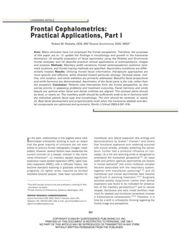
WORLD JOURNAL OF ORTHODONTICSRicketts/GrummonsFig 3 Head positioning for posteroanterior image.to detect asymmetry during diagnosis, factor it intotreatment planning options, and set appropriateexpectations for different treatment options. This issuperior to a rationale for discovering it later in treatment, and managing this as the case progresses.cephalometer is critical for the frontal exposure. Forimprovement in images, Bench27 modified the technique as follows: A line is scribed on the ear rodassembly at a point 15 mm above the ear rod (Fig3). The height of the orbit is about 3 cm, and the lateral canthus is essentially at the center of the orbit,or 15 mm. The patient should be seated snuglyagainst the top of the ear rods with the head positioned so that the lateral canthus of the eye islocated on a level with that line. The jaw is held inthe habitual occlusion. The exposure is up to 3 timesthat used for the lateral headplate. Experience hasshown that a properly oriented frontal headfilm willshow the top of the petrous portion of the temporalbone to lie near the center of the orbit. Also, the Jpoints and Ag points can be identified, and nasalcavity morphology will be visible. The zygomaticarches will be revealed in cross section.TRANSVERSE AND FRONTALPERSPECTIVESThe transverse perspective, as viewed from the front,deserves priority from initial assesment through thetherapeutic process. In smile design, Langlade17 andGrummons 4,11 have described and emphasizedfacial/dental asymmetry and frontal analysis key factors. The simplified frontal analysis emphasizes thefollowing: (1) the maxillary dental midline shouldcoincide with the skeletal midsgittal reference (MSR)line; (2) the occlusal plane should be level, or nearlyso; (3) the chin location should be centered or disguised to appear neutral, or options for this correction should be offered to the patient. These keyaspects of the frontal dimension need to be effectively managed and communicated to patients.Patients often seek re-treatment not because oftheir dentition, but rather because they are notpleased with the overall facial and esthetic outcome.If a patient’s teeth are straight, with the occlusionfunctional, yet the smile line is tipped or the maxillaryincisors are off-center from the facial midline, thepatient probably will not be pleased with the result.Frontal film and interpretations:Ricketts methodThis method requires a better discipline for tracing thefrontal, as compared to the lateral image. There isgreater superimposition of skeletal and dental structures. With study of the structural images, a depictioncan include even the mandibular condyles and articular eminence. Literally, all the teeth can be identifiedin the mixed and permanent dentitions (Fig 4). Areview of skulls is helpful in the learning process.The Ricketts tracing template (Dome) includestooth outlines in the frontal dimension and is ofgreat help. Locating the buccal surfaces of posteriorteeth and positioning the template over them canallow the clinician to trace a good representation.Incisal edges of anteriors likewise can be locatedwith the template. Not all the complete structuresneed be traced, but the issue is their visibility. In particular, the first molars and central incisors shouldHead positioning, exposure, andanatomic displayFor the frontal image, inconsistency in head positioning with the head tipped downward at one settingand upward in another makes analysis or comparisons difficult. Therefore, posturing the patient in the300COPYRIGHT 2003 BY QUINTESSENCE PUBLISHING CO, INC.PRINTING OF THIS DOCUMENT IS RESTRICTED TO PERSONAL USE ONLY.NO PART OF THIS ARTICLE MAY BE REPRODUCED OR TRANSMITTED IN ANY FORMWITHOUT WRITTEN PERMISSION FROM THE PUBLISHER.
VOLUME 4, NUMBER 4, 2003aRicketts/GrumonsbcFig 4 Frontal tracings of symmetric examples. (a) Gnomic growth. (b) Child, mixed dentition. (c) Adult.Table 1 Maxillary width (J-J’)in malesAge (y)Fig 5 Frontal planes of reference.3456789101112131415161718192021be identified as accurately as possible. The center ofthe cross section of the zygomatic arch is selected,as points Za and aZ, for drawing the frontal Frankfortplane when the two are connected. A second checkreference is the connection of Zf points as a basicfrontal reference. From the Frankfort plane, a perpendicular line is dropped from the crest on thefrontal or top of the nasal septum. This will form abasic coordinate as a starting frame of reference.11,14,23,28 This is depicted on a composite of N 82 normal adults gathered by the Foundation forOrthodontic Research (FOR) and Education (FORE).The next step toward frontal diagnosis is the connection of corresponding points bilaterally. These arepoints Nf (nasal floor), J, Ag, and the bisection of theWidth (mm)55565758596061626364656667686970717273first molar occlusion (or second deciduous molars).At the deciduous level, when the lines of connectionare parallel, a vertical symmetry is presented. Vertical lines established are Zf-Ag and J-Ag (Fig 5).Maxillary widthOne of the alerts to a Divine Proportion or Fibonacciphenomena was that maxillary width at the J point(which represents also width at the tuberosity) wasdouble that of nasal width increase. The growthvalue conveniently was 1.0 mm per year startingwith 55 mm at 3 years of age, in males (Table 1).301COPYRIGHT 2003 BY QUINTESSENCE PUBLISHING CO, INC.PRINTING OF THIS DOCUMENT IS RESTRICTED TO PERSONAL USE ONLY.NO PART OF THIS ARTICLE MAY BE REPRODUCED OR TRANSMITTED IN ANY FORMWITHOUT WRITTEN PERMISSION FROM THE PUBLISHER.
WORLD JOURNAL OF ORTHODONTICSRicketts/GrummonsTable 2 Mandibular width(Ag-gA) in malesAge (y)3456789101112131415161718192021Table 3 Maxillomandibular differential andindex values in malesWidth .585.086.588.089.591.092.594.0Maxillary MandibularAge 0.080.579.2780.078.0Table 4 Nasal cavity and maxillary differentialand index values in malesAge (y)Nasal 041.542.0381318Mandibular widthIf the proportion is calculated at different ages, asurprising regularity is observed. The value or ratioof maxilla to mandible is about 80%, and the ratio ofnasal cavity to maxilla ranges from 40% to 42%(Table 4).As stated before, the selection of Ag point was fortuitous. It was investigated because it was in a reasonable plane with the J point and could be related withthe mandibular molar teeth. Starting at 68.00 mmat 3 years of age, it grows in width essentially 1.5mm each year, to have a mean at age 21, in males,of around 94 mm. The clinical deviation is around2.5 mm (Table 2).Comparative widths and symmetryThe maxillomandibular width relationship in theface, as expressed by distance from the J point laterally to the frontofacial plane (midsagittal plane), alsois age linked. This is a good value for symmetry, aswell as actual s
Robert M. Ricketts, DDS, MS1/Duane Grummons, DDS, MSD2 Aims: Many clinicians have not employed the frontal perspective. Therefore, the purposes of this paper are to: (1) update the findings in morphology and growth