Transcription
Lecture 12Physical Vapor Deposition: Evaporation andSputteringReading:Chapter 12Georgia TechECE 6450 - Dr. Alan Doolittle
EvaporationEvaporation and Sputtering (Metalization)For all devices, there is a need to go fromsemiconductor to metal. Thus we need a means todeposit metals. Many of these techniques used formetal deposition can be used to deposit other materialsas well.Several methods are currently used for deposition ofmetal layers.Physical Vapor Deposition techniques (PVD)1.) Evaporation2.) Sputtering3.) Chemical Vapor Deposition (CVD)4.) Electrochemical techniques1.) Evaporation:Advantages: Highest purity (Good for Schottkycontacts) due to low pressures.Disadvantages: Poor step coverage, forming alloys canbe difficult, lower throughput due to low vacuum.Evaporation is based on the concept that there exists afinite “vapor pressure” above any material. Thematerial either sublimes (direct solid to vaportransition) or evaporates (liquid to vapor transition).Georgia TechECE 6450 - Dr. Alan Doolittle
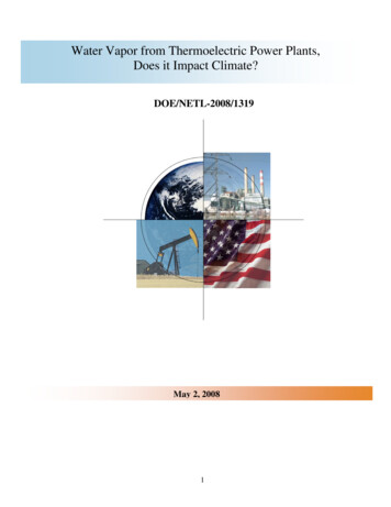
Evaporator SystemsTwo main types of evaporators: E-beam and filament.WafersValveHeatedMaterialVacuum ChamberAir InletValveValveRoughPumpGeorgia TechCryo orTurboPumpECE 6450 - Dr. Alan Doolittle
Evaporator PhysicsFor evaporation, the vapor pressure is,Pevaporation 3x10¹² 3/ 2 T H 1/ 2 NkT e Po e Ea kT where is the surface tension of the liquid, N is avagadro’s number, and H is the enthalpy of evaporation(the energy required to convert from a liquid to gas phase).We can define the number of molecules crossing a plane per unit time as,J P22 kTmVirtual Source: Point in free spacewhere the pressure drops enough toresult in molecular flow. Closer tothe source viscous flow applies.where P is pressure in Pascals, k is Boltzsmans constant, T is absolutetemperature and m is the atomic or molecular mass.If the liquid is assumed to be at a constant temperature, and the crucible(container holding the liquid) has a constant area opening, the wafer is locatedon a sphere as defined by figure 12-3, the the deposition rate is,Rd m2 k 2Pevaporation Area4 r 2Twhere is the mass density (kg/m2), Area is the area of the wafer, and r isthe radius of the sphere defined in figure 12-3.Georgia TechECE 6450 - Dr. Alan Doolittle
Evaporation Step CoverageThe step coverage of evaporated films is poordue to the directional nature of the evaporatedmaterial (shadowing) (see figure 12-5). Heating(resulting in surface diffusion) and rotating thesubstrates (minimizing the shadowing) help withthe step coverage problem, but evaporation cannot form continuous films for high aspect ratios(AR step height/step width or diameter) greaterthan 1.We need a less directional metallizationscheme Higher pressures!Georgia TechECE 6450 - Dr. Alan Doolittle
Sputtering2.) Sputtering:Advantages: Better step coverage, less radiation damage than E-beam evaporation, easier to depositalloys.Disadvantages: Some plasma damage including implanted argon. Good for ohmics, not Schottkydiodes.A plasma at higher pressure is used to “knock” metal atoms out of a “target”. These energetic atomsdeposit on a wafer located near the target. The higher pressure produces better step coverage due tomore random angled delivery. The excess energy of the ions also aids in increasing the surface mobility(movement of atoms on the surface).Georgia TechECE 6450 - Dr. Alan Doolittle
SputteringA threshold energy for the release of an atom from the targetexists, below which the atom is not “sputtered”.This threshold energy is,E threshold 4 M1 M 2Heat of Vaporizationwhere (1 )( M1 M 2 ) 2The sputter yield (ratio of target atoms expelled to incidentatoms impinging on the target) increases with increasingenergy (plasma power or DC bias). (See 12-13).Georgia TechECE 6450 - Dr. Alan Doolittle
Sputtering DetailsFilm MorphologyDeposited films can be: (See 12-20).1.) Porous and/or Amorphous — Results from poor surface mobility low temperature, low ion energy (lowRF power/DC bias or higher pressures less acceleration between collisions).2.) “T-zone”: Small grain polycrystalline, dense, smooth and high reflectance (the sweet spot for most metalprocesses) Results from higher surface mobility higher temperature or ion energy3.) Further increases in surface mobility result in columnar grains that have rough surfaces. These roughsurfaces lead to poor coverage in later steps.4.) Still further increases in surface mobility result in large (non-columnar) grains. These grains can be goodfor diffusion barriers (less grain boundary diffusion due to fewer grains) but pose problems for lithography dueto light scatter off of large grains, and tend to be more rigid leading to more failures in electrical lines.31Georgia Tech42 or TECE 6450 - Dr. Alan Doolittle
Sputtering DetailsOften, it is needed to sputter alloys instead of pure elemental metals (Al Si Cu). Consider the problem ofelectromigration in AluminumCauses:Electron momentum transfer to the ions in high current density lines.Solution: Add a small number (typically 3-5%) larger atoms such as copper that “anchor” the aluminum atoms inplace or replace the entire metal line with larger atoms such as copper so that each atom is more difficult to move.When sputtering Aluminum and Copper alloys, the film on the wafer has more copper than the target. Reason: Atthe target, the argon has achieved high enough energy to sputter the Al and Cu evenly. However, in the gas (lowerelectric field), the heavier atoms are less effected by light sputter gas. The light Al can gain enough energy to beabove it’s evaporation temperature when it hits the wafer. Thus, the Cu sticks, but the Al does not.The target material must be tailored to the sputter conditions to get the desired film composition!Georgia TechECE 6450 - Dr. Alan Doolittle
Sputtering DetailsFilm stress:Film stress can result in wafer bowing (problems with lithography), film cracking or peeling. There is 2 kindsof films stress:1.) Extrinsic Stress (forces acting on the wafer due to sources external to the deposited film)Example: Thermal induced stress:Stressthermal mismatchYoungs Modulus of film 1 ( Poissons' s Ratio of film)Tdeposition ( film wafer )dTTroomwhere is the thermal expansion coefficient [1/degree].2.) Intrinsic Stress (forces acting on the wafer due to sources internal to the deposited film)These can be differences in atomic spacing, variations in grain orientation or size, grain growth duringdeposition, and even implanted or trapped gaseous impurities such as argon. These depend strongly on thedeposition conditions.Both of these stresses can lead to a bowed wafer with deflection defined in figure 12-28. ED 2Stress t (1 v )3R 2Where E is the films Youngs modulus, is the filmsPoisson ratio, D is the wafer thickness, t is the filmthickness, R is the radius of the wafer bow.Georgia TechECE 6450 - Dr. Alan Doolittle
Sputtering DetailsSelf Aligned ProcessSelf aligned Gate ProcessSee figure Sze 9-6Georgia TechECE 6450 - Dr. Alan Doolittle
Sputtering DetailsMulti-Level MetalizationVerbally DiscussDamascene with aid ofAdded Slides.Multi-level MetallizationSee figure Sze 9-17Georgia TechECE 6450 - Dr. Alan Doolittle
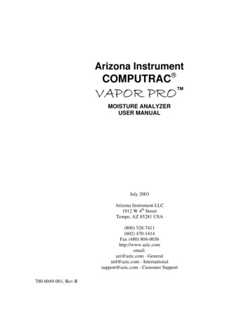
Intel Xeon E3-130V2 General StructureA closer TEM image (Fig. 4) shows the lower metal stack and a pair of multi-fin NMOS and PMOStransistors. This section is parallel to the gate, across the fins, and we can see the contact trenches andmetal levels M1 up to M5.We have to digress here a little to explain what we’re looking at. A typical TEM sample is 80 – 100nm thick, to be thin enough to be transparent to the electron beam and at the same time have enoughphysical rigidity so that it does not bend or fall apart.Here we are trying to image structures in a die with a gate length of less than 30 nm; so if we make asample parallel to the gate, and if the sample is aligned perfectly along the centre of the gate, then itwill contain the gate plus at least part of the source/drain (S/D) silicon and contacts on either side.Georgia TechECE 6450 - Dr. Alan Doolittle
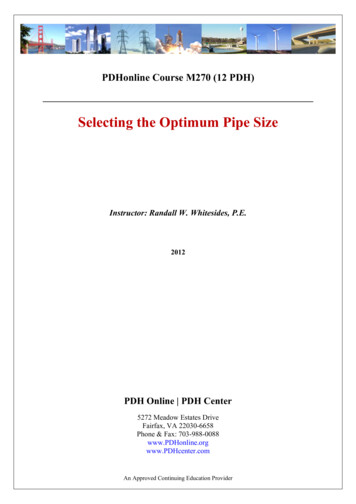
TEM Image of Lower Metals and NMOS and PMOS (right) TransistorsThat is what we see above – I have labeled the gate and contact stripes,and we have PMOS on the right and NMOS on the left. The tungstenfilled contacts obscure parts of the gate, but we can clearly see that thePMOS S/D fins have epitaxial growth on them, and the fins have anunexpected slope – a little different from Intel’s tri-gate schematic shownlast yearGeorgia TechECE 6450 - Dr. Alan Doolittle
These can be differences in atomic spacing, variations in grain orientation or size, grain growth during deposition, and even implanted or trapped gaseous impurities such as argon. These depend strongly on the deposition conditions. Both of these stresses can lead