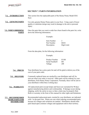
Transcription
Henny PennyOpen Fryer ElectricModel OE-100TECHNICAL MANUAL
LIMITED WARRANTY FOR HENNY PENNY APPLIANCESSubject to the following conditions, Henny Penny Corporation makes the following limited warranties tothe original purchaser only for Henny Penny appliances and replacement parts:NEW EQUIPMENT: Any part of a new appliance, except lamps and fuses, which proves to bedefective in material or workmanship within two (2) years from date of original installation, will berepaired or replaced without charge F.O.B. factory, Eaton, Ohio, or F.O.B. authorized distributor.To validate this warranty, the registration card for the appliance must be mailed to Henny Pennywithin ten (10) days after installation.REPLACEMENT PARTS: Any appliance replacement part, except lamps and fuses, whichproves to be defective in material or workmanship within ninety (90) days from date oforiginal installation will be repaired or replaced without charge F.O.B. factory, Eaton, Ohio,or F.O.B. authorized distributor.The warranty for new equipment and replacement parts covers only the repair or replacement of the defectivepart and does not include any labor charges for the removal and installation of any parts, travel or otherexpenses incidental to the repair or replacement of a part.EXTENDED FRYPOT WARRANTY: Henny Penny will replace any frypot that fails due to manufacturingor workmanship issues for a period of up to seven (7) years from date of manufacture. This warranty shall notcover any frypot that fails due to any misuse or abuse, such as heating of the frypot without shortening.0 TO 3 YEARS: During this time, any frypot that fails due to manufacturing or workmanship issues will be replaced at no charge for parts, labor, or freight. Henny Penny will eitherinstall a new frypot at no cost or provide a new or reconditioned replacement fryer at no cost.3 TO 7 YEARS: During this time, any frypot that fails due to manufacturing or workmanship issues will be replaced at no charge for the frypot only. Any freight charges and laborcosts to install the new frypot as well as the cost of any other parts replaced, such as insulation, thermal sensors, high limits, fittings, and hardware, will be the responsibility of theowner.Any claim must be represented to either Henny Penny or the distributor from whom the appliance waspurchased. No allowance will be granted for repairs made by anyone else without Henny Penny's writtenconsent. If damage occurs during shipping, notify the sender at once so that a claim may be filed.THE ABOVE LIMITED WARRANTY SETS FORTH THE SOLE REMEDY AGAINST HENNY PENNYFOR ANY BREACH OF WARRANTY OR OTHER TERM. BUYER AGREES THAT NO OTHER REMEDY (INCLUDING CLAIMS FOR ANY INCIDENTAL OR CONSQUENTIAL DAMAGES) SHALL BEAVAILABLE.The above limited warranty does not apply (a) to damage resulting from accident, alteration, misuse, orabuse; (b) if the equipment's serial number is removed or defaced; or (c) for lamps and fuses. THE ABOVELIMITED WARRANTY IS EXPRESSLY IN LIEU OF ALL OTHER WARRANTIES, EXPRESS OR IMPLIED, INCLUDING MERCHANTABILITY AND FITNESS, AND ALL OTHER WARRANTIES AREEXCLUDED. HENNY PENNY NEITHER ASSUMES NOR AUTHORIZES ANY PERSON TO ASSUMEFOR IT ANY OTHER OBLIGATION OR LIABILITY.
Model OE-100Table of ContentsSECTION 1.TROUBLESHOOTING. 1-11-1. INTRODUCTION . 1-11-2. TROUBLESHOOTING. 1-1SECTION 2.MAINTENANCE . 2-12-1. INTRODUCTION . 2-12-2. TEST INSTRUMENTS . 2-12-3. REMOVING THE CONTROL PANEL . 2-12-4. THERMAL SENSOR . 2-22-5. HIGH TEMPERATURE LIMIT CONTROL . 2-32-6. HEATING ELEMENTS. 2-52-7. CONTACTORS . 2-72-8. FAN . 2-82-9. COOK/PUMP SWITCH . 2-92-10. FUSES . 2-102-11. DRAIN SWITCH . 2-102-12. FILTER HEATER SWITCH . 2-112-13. FILTER HEATER . 2-122-14. FILTERING SYSTEM . 2-132-15. FILTER VALVE . 2-142-16. FILTER PUMP REPAIR . 2-142-17. PUMP REMOVAL . 2-152-18. PUMP AND MOTOR REPLACEMENT . 2-162-19. COOLING FAN MAINTENANCE. 2-16SECTION 3.PARTS INFORMATION . 3-13-1. INTRODUCTION . 3-13-2. GENUINE PARTS . 3-13-3. WHEN ORDERING . 3-13-4. PRICES . 3-13-5. DELIVERY . 3-13-6. WARRANTY . 3-13-7 RECOMMENDED SPARE PARTS FOR DISTRIBUTORS . 3-1Henny Penny Distributor List (Domestic and International)206FM06-001Revised 4-02-09i
Model OE-100SECTION 1. TROUBLESHOOTING1-1. INTRODUCTIONThis section provides troubleshooting information in the form ofan easy-to-read table.If a problem occurs during the first operation of a new fryer,recheck the installation per Section 2 of the Operator Manual.Before troubleshooting, always recheck the operating procedureper Section 3 of the Operator Manual.1-2. TROUBLESHOOTINGDisplayIn the event of a control system failure, the digital display willshow an "Error Message". These messages are coded E4, E5, E6,E41, E50, E51, and E53. The following table will assist you introubleshooting possible malfunctions within the unit:CauseCorrectionE4Control too hotTurn switch to OFF position, then turnswitch back to POWER position. If displayshows E4, heating circuits, insulation, andfan should be checked. (See Section 2-19.)E5Shortening too hotUnplug unit, or turn off circuit breaker tounit. If display still shows E5, heating andhigh limit circuits should be checked perSection 2-5 and Section 2-6.E6Temperature probe failureUnplug unit, or turn off circuit breaker tounit. If display still shows E6, check temperature probe connection at board. If connection isgood, replace temperature probe.E10High temperature limit failureReset high temperature limit by manuallypushing on lever, behind door. (see Figure3-2 of the Operator Manual). If high limit doesnot reset, replace high limit per Section 2-5.E41, E50,E51, E53Control errorsUnplug unit, or turn off circuit breaker tounit. If display still shows an error, reinitialize the control (see Section 4-4 ofOperator Manual). If error still persists,change the control board.2941-1
Model OE-100ProblemWith switch in COOKposition and switchlight not illuminated,fryer is completelyinoperative (no power).CauseOpen circuitCorrection Check to see if unit is plugged in. Check breaker or fuse at supplybox. Check control panel fuse perSection 2-10. Check COOK/OFF/PUMP switchper Section 2-9. Replace if defective. Check voltage at wall receptacle. Check cord and plug.With switch in COOKposition switch lightis illuminated, butall other lights areare extinguished.Open drain valve Close drain valve.Defective drain switch Check drain switch perSection 2-11.Shortening will notheat but lights areilluminated.Faulty contactor Check contactor per Section 2-7.Faulty temperature probe Check temperature probe persection 2-4. "Error Message" E6.Faulty high temperature limit Check high temperature limitper Section 2-5.Low or improper voltage Using a voltage meter, check wallreceptacle voltage against therated voltage on data plate.Weak or burned out elements Check heating elements perSection 2-6.Points in contactor bad Check contactor per Section 2-7.Wires loose Tighten wire connectors.Burned or charred wire connection Replace wire and clean connectors.Heating of shorteningtoo slow.5931-2
Henny PennyModel OE-100SECTION 2. MAINTENANCE2-1.INTRODUCTIONThis section provides procedures for checking and replacement of thevarious parts used within the unit. Before replacing any parts, refer toSection 1, Troubleshooting. It will aid you in determining the cause of aparticular malfunction.2-2.TEST INSTRUMENTSYou may use two test instruments to check the electric components. A continuity light. An ohmmeter.When the manual refers to the circuit being closed, the continuity lightwill be illuminated or the ohmmeter should read zero (0) unless otherwise noted.When the manual refers to the circuit being open, the continuity lightwill not illuminate or the ohmmeter will read one (1).A continuity light cannot be used to check coils or motors.2-3.REMOVING THECONTROL PANELTo replace parts located inside the fryer, you will need to remove thecontrol panel. The following steps provide the correct procedure.SHOCK HAZARDTo avoid electrical shock or property damage, move thepower switch to “OFF” and disconnect main circuit breaker,or unplug cord at wall receptacle.1.593Remove the decorative strips, located on each side of the controlpanel, by removing the screw located on the bottom of eachdecorative strip.2-1
Model OE-1002-3.REMOVING THECONTROL PANEL(Continued)2.Control panel swings out, hinged on the left side of the panel.When completely removing control panel, all wiring must beunplugged from control panel. Be sure to mark wires beforeremoving.3.Pulling down on the spring loaded hinge pin, pull control panelstraight out to completely remove.4. Install control panel in reverse order.2-4.TEMPERATURE PROBEThe temperature probe determines the shortening temperature. If amalfunction does occur, an E6 will be displayed on the digital readout.Turn unit to OFF position, then back to COOK position. If E6 is stilldisplayed, the temperature probe must be replaced by following thesesteps:SHOCK HAZARDTo avoid electrical shock or property damage, move powerswitch to “OFF” position and disconnect main circuitbreaker, or unplug cord at receptacle.1. Drain the shortening from frypot.2. Remove the decorative strips, located on each side of the controlpanel, by removing the screw located on the bottom of eachdecorative strip, and let control panel swing out.5932-2
Model OE-1002-4.TEMPERATURE PROBE(Continued)4. Unplug electrical wires from control panel board that are attachedto temperature probe.5. Using a 1/2" wrench, loosen screw nut from pot fitting and pulltemperature probe bulb straight out from pot fitting.6. Install new temperature probe, making sure the temperatureprobe extends through pot wall, up to the outer diameter of theheating element.Care must be taken not to extend the temperature probebeyond this point or damage to probe could result.Also, when installing new temperature probe, you must usea new locking ferrule in screw nut. Snug screw nut up andtighten 1/4 turn past this point. Do not overtighten screwnut, or damage to probe could result.2-5.HIGH TEMPERATURELIMITThe high temperature limit is a manual reset device which senses thetemperature of the shortening. If the shortening temperature exceedsthe safe operating limit, the high temperature limit opens and shuts offthe heat to the frypot.The high limit light then illuminates and the high temperature limit mustbe manually reset.Disconnect the two wires from the high temperature limit. Check forcontinuity between the two terminals after resetting the high limit. If thecircuit is open, replace the high limit following these procedures. If thecircuit is closed, the high limit is not defective. Reconnect the twoelectrical wires.10912-3
Model OE-1002-5.HIGH TEMPERATURELIMIT CONTROL(Continued)Before following these steps, place POWER switch in theOFF position and unplug the power cord or open the wallcircuit breaker.1. If the tube is broken or cracked, the control will open, shutting offelectrical power. The control cannot be reset.Use replacement high limit, part no.16337, 420 degree.2. Drain shortening from the frypot.3. Remove control panel per Section 2-3.4. Remove the retainer securing the silicone gasket.5. Loosen small inside screw nut on capillary tube.6. Remove capillary bulb from bulb holder inside the frypot.7. Straighten the capillary tube.8. Remove larger outside nut that threads into pot wall.9. Remove the two nuts that hold the high limit bracket from controlpanel area.10. Lift defective control from control panel area.11. Insert new control and replace nuts to bracket.12. Uncoil capillary line, starting at capillary tube, and insert throughfrypot wall.To avoid electrical shock or other injury, the capillary linemust run under and away from all electrical power wiresand terminals. The tube must never be in such a positionwhere it could accidentally touch the electrical powerterminals.13. Carefully bend the capillary bulb and tube toward bulb holder onheating elements.14. Slip capillary bulb into bulb holder located on heating elements.Pull excess capillary line from pot and tighten nut into frypot wall.4092-4
Model OE-1002-5.HIGH TEMPERATURELIMIT (Continued)15. With excess capillary tube pulled out, tighten smaller nut.Do not overtighten nut or damage to capillary tube mayresult.16. Replace front panel.17. Refill with shortening.2-6.HEATING ELEMENTSHeating elements are available for 208 and 480 voltage.Check the data plate to determine the correct voltage.If the shortening's temperature recovery is very slow or at a slowerrate than required, this may indicate defective heating element(s). Anohmmeter will quickly indicate if the elements are shorted or open.SHOCK HAZARDTo avoid electrical shock or property damage, move thepower switch to “OFF” and disconnect main circuit breaker,or unplug cord at wall receptacle.1. Remove the control panel. Refer to Section 2-3.2. Perform an ohm check on one element at a time, with wiresdisconnected from element. If the resistance is not within tolerance, replace the element.ResistanceVoltageWattagein Ohms .759.612-5
Model OE-1002-6.HEATING ELEMENTS(Continued)Replacement1. Drain the shortening from the frypot.2. Remove the heating element wire from the terminals by removingthe nuts and washer. Label each so it can be replaced in the sameposition on the new element.3. Remove the retainer securing the silicone gasket.4. Loosen the bolts on the four element spreaders.5. Slide the element spreaders to the center of the heating element.6. Remove the brass nuts (4) and washers (3) which secure the endsof the elements through the frypot wall.7. Remove the heating elements from the frypot as a group by liftingthe far end and sliding them up and out toward the rear of thefrypot.8. Install new heating elements with new "0" rings (2) mounted onterminal ends and spreaders loosely mounted in the center of theheating elements.9. Replace the heating elements, terminal end first, at approximately450 angle, slipping the terminal ends through the front end of thefrypot.10. Replace the brass nuts (4) and washers (3) on the heating elementterminals. Tighten the brass nuts to 30 foot pounds of torque.11. Move the element spreader from the center of the element into aposition which will spread each element apart evenly on all foursides and tighten.12. Reconnect the wires to the appropriate terminal as labeled whenthey were removed.13. Replace the front control panel.14. Connect the power cord to the wall receptacle or close wallcircuit breaker.TURN OFF POWERSwitch must be in “OFF” position until shortening isadded to frypot or damage to heating elements could result.15. Replace the shortening in the frypot.10912-6
Model OE-1002-7.CONTACTORSSHOCK HAZARDThe following tests are performed with the wall circuitbreaker closed and the Power switch in the ON position.Make connections before applying power, then take readings. Remove power before removing meter leads, orelectrical shock may result.1. With power applied, increase setpoint temperature setting allowing heat contactor to activate.Test PointsHeat Contactorfrom terminal 34 to 35from terminal 35 to 36from terminal 34 to 36ResultsThe voltageshould read thesame at eachterminal.Test PointsPrimary Contactorfrom terminal 27 to 28from terminal 28 to 29from terminal 27 to 29ResultsIt shouldcorrespond tothe voltagerating stated onthe data plate.If either contactor is defective, it must be replaced as follows:1. Remove electrical power supplied to the fryer by unpluggingor opening the wall circuit breaker.2. Remove only those wires directly connected to the contactorbeing replaced. Label the wires.3. Remove the two mounting screws on the base plate andremove contactor.4. Install the new contactor and tighten the two mountingscrews.5. Connect the labeled wires to their respective positions.6. Install the control panel.7. Reconnect power to the fryer and test the fryer for properoperation.5932-7
Model OE-1002-7.CONTACTORS(Continued)The Henny Penny OE-100 requires two switching contactors. Located on the bottom is the primary contactor with the heat contactorstacked to the top of the primary. When closed, the primary contactorcompletes the heat circuit. It also supplies power to the heat contactor.SHOCK HAZARDTo avoid electrical shock or property damage, move thepower switch to “OFF” and disconnect main circuit breaker,or unplug cord at wall receptacle.1. Remove the control panel. Refer to Section 2-3.2. Perform a check on the contactor as follows:Test PointsResultsfrom 23 to 29from 24 to 28from 25 to 27from 30 to 34from 31 to 35from 32 to 36from 22 to 26from 33 to 372-8.FANopen circuitopen circuitopen circuitopen circuitopen circuitopen circuitohm reading 415ohm reading 415The Henny Penny OE-100 has a fan in the circuit which operates onlywhen the power switch is in the COOK position. The fan helps keepthe control panel cool by pulling out heat from between the controlpanel and frypot.The replacement of a faulty fan is as follows:SHOCK HAZARDTo avoid electrical shock or property damage, move thepower switch to “OFF” and disconnect main circuit breaker,or unplug cord at wall receptacle.1. Remove control panel per Section 2-3.5932-8
Model OE-1002-8.FAN (Continued)2. Label and disconnect fan motor wires.3. Remove the four screws, washers, and nuts securing the fan to theheat shield.4. Remove the fan from th
2-2. TEST INSTRUMENTS You may use two test instruments to check the electric components. A continuity light. An ohmmeter. When the manual refers to the circuit being closed, the continuity light will be illuminated or the ohmmeter should read zero (0) unless other-wise noted.
