Transcription
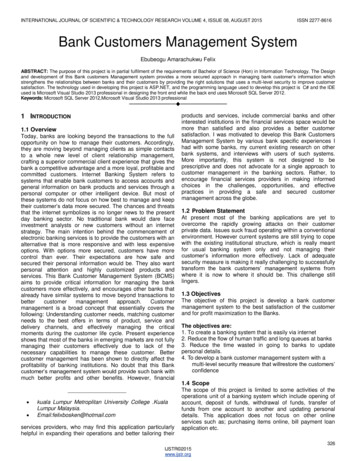
MICROSTAR SYSTEM MANUAL page 1 of 21MICROSTAR LOAD BANK SYSTEMTECHNICAL MANUALAPRIL 2012The information herein is the property of Simplex, Inc. and/or its subsidiaries. Without writtenpermission, any copying, transmitting to others, and other use except that for which it isloaned, is prohibited.Simplex, Inc., 270 Riverside Parkway Suite G Austell, GA 30168 678-214-6575 Fax 678-214-6670Printed in the USA. www.simplexdirect.com
MICROSTAR SYSTEM MANUAL page 2 of 21ContentsDESCRIPTION . 2Control System . 3Cooling System . 3Load System. 3PRIMARY INSPECTION . 4INSTALLATION. 4SETUP . 5LOCAL CONTROL . 5Load Dump . 5FAILURE DETECTION. 5MAINTENANCE . 5Each Operation . 5Every 50 Hours or 6 Months . 6TROUBLESHOOTING . 6Cooling Fan Motor Will Not Operate . 6Cooling Failure Indicated . 6Metering System Does Not Operate Properly . 6Some Load Steps Cannot Be Energized. 6APPENDIX A - ABBREVIATIONS USED IN THIS MANUAL. 7APPENDIX B - CALCULATIONS & FORMULAS . 8APPENDIX C - TORQUE VALUES. 9Simplex, Inc., 270 Riverside Parkway Suite G Austell, GA 30168 678-214-6575 Fax 678-214-6670Printed in the USA. www.simplexdirect.com
MICROSTAR SYSTEM MANUAL page 3 of 21AIR FLOW AND VISUAL DIAGRAMDESCRIPTIONSimplex Microstar load bank units are precision test instruments specifically designed to apply discrete,selectable heat loads to a cooling source. The Microstar also provides a means for routine maintenance toassure long term reliability of the product and readiness of the building cooling systems. The Microstar fitsa 19-inch server rack of most all types, round/square/hole/threaded/unthreaded.The cabinet on the Microstar is rated Environmental Type 1.The illustrations in this manual are examples only and may differ from your load bank.Building cooling source testing is accomplished by applying resistive load steps to generate predeterminedamounts of heat (KW).Load application is by magnetic contactor. Load steps 1-5 are protected by 15 amp class-CC fuses, andload steps 6-7 are protected by 20 amp class-CC fuse.Operating controls are provided locally via the control panel of switches located on the face of the unit. Thecontrol system is composed of 24VDC components. Common serviceable components include control fusesand load application fuses. Lamps on the face panel of the load bank indicate the operating status of theMicrostar .The local control panel contains the following components: Green “Cooling Active” LightRed “Over Temperature” LightOn/Off SwitchFan Speed PotentiometerLoad Steps 1-7The “Cooling Active” lamp, green, illuminates when control power is available and the load may be applied.Simplex, Inc., 270 Riverside Parkway Suite G Austell, GA 30168 678-214-6575 Fax 678-214-6670Printed in the USA. www.simplexdirect.com
MICROSTAR SYSTEM MANUAL page 4 of 21DESCRIPTION - ContinuedThe Microstar is protected against cooling failure (loss of cooling air flow, high temperature intake, or highexhaust air temperature, all of which could damage the Microstar or present a safety hazard to theoperator.) When a cooling failure occurs the automatic safety feature in the control system immediatelyremove all load. The malfunction must be corrected and the system must be reset by turning the Microstar “Off” then “On” before the load can be re-applied.CONTROL SYSTEMThe control system allows the operator to apply a desired load to the test source and measure theresponse of the test source to the load. This system also contains the circuitry utilized todisconnect the Microstar from the test source in the event of cooling failure and/or improperlypositioned operating controls.Control Power (24VDC) is supplied internally via the load source through the power supply. The fan starts withthe power on switch. The fan speed is controlled via a potentiometer in conjunction with a current transformerlocated on the load wires. Once the current transformer detects a high enough amp draw, the range on thepotentiometer allows for higher fan speeds.CONTROL PANEL DIAGRAMCOOLING SYSTEMThe load elements in the Microstar are cooled by a forced air system consisting of a one fan system. Thefan motor is energized by the on switch on the control panel and protected by control fuses.LOAD SYSTEMThe Load System consists of independently controlled resistive load elements specifically designed for theMicrostar . The Load steps are protected by 200,000aic,600VAC fuses.Simplex Resistive Load Elements conservatively operate at approximately half the maximum temperaturerating for the alloy (1080 F vs. 1920 F).See Parts Legend Drawing for specific elements used.These elements are rigidly supported by high-temperature, ceramic-clad, stainless-steel support rods.Element-to-element short circuits are virtually eliminated. The elements are assembled in the elementchamber in a fashion such that each element can be serviced without disturbing adjacent trays.Simplex, Inc., 270 Riverside Parkway Suite G Austell, GA 30168 678-214-6575 Fax 678-214-6670Printed in the USA. www.simplexdirect.com
MICROSTAR SYSTEM MANUAL page 5 of 21PRIMARY INSPECTIONPreventative visual inspections of the shipping crate and Microstar is advised. Physical or electricalproblems due to handling and vibration may occur. Never apply power to a Microstar before performingthis procedure. The following Nine Point/30 minute inspection is recommended before installation, as part ofother 50hour/6month maintenance schedule and whenever the Microstar is relocated:1. If the crate shows any signs of damage examine the Microstar in the corresponding areas forsigns of initial problems.2. Check the entire outside of the cabinet for any visual damage which could cause internal electricalor mechanical problems due to reduced clearance.3. Inspect all cam locks for smooth and safe operation.4. Flip all switched to ensure smooth operation.5. Check cooling system by inspecting the fan. Check fan blades and fan shroud for stress fractures.6. Inspect all relays, timers, and control module by opening removing the cover. Make sure allcomponents are secure in their bases and safety bails are in place. Spot check electricalconnections for tightness. If any loose connections are found inspect and tighten all remainingconnections.7. Examine all accessible internal electrical components such as fuses, contactors and transformers.Check lugged wires at the components.8. Inspect bottom of crate/enclosure for any components that may have been jarred loose duringshipment such as indicator light lenses, switches, etc.9. Visually inspect element chamber for foreign objects, broken ceramic insulators, and mechanicaldamage.If any problems are observed during Primary Inspection call the Simplex Service Manager at 217483-1600 (24hrs.)INSTALLATIONThe Microstar is to be installed into a 19 inch server rack, EIA-310D. This is achieved by lining thepushpins with the corresponding holes in the rack, then use turn the cam lock keys to press lock the loadbank into position. The load elements in the Microstar are cooled by a forced air system which takes air inthe front and discharges through the rear of the device. The Microstar must be installed with appropriateclearances on the intake and exhaust sides of the panels. There must be a minimum clearance of 2 feet on the inlet and outlet of the Microstar Never point the exhaust at a nearby surface or object which may be adversely affected by hightemperature. Consider that multiple Microstar units and other equipment in the area will create excessivetemperature spikes if equally spaced. It is important to properly balance the phase legs used to power multiple load banks. Always havethe Microstar installed by trained personnel ONLY.Failure to properly install the Microstar may result in substantial damage to or the destruction ofthe Microstar and adjacent equipment.Do Not allow the Microstar to operate unattended for anextended period of timeAlways remove all power fromthe load bus and all fan/controlpower before servicing the LoadBank. Never operate or servicea Load Bank that is not properlyconnected to an earthground.Simplex, Inc., 270 Riverside Parkway Suite G Austell, GA 30168 678-214-6575 Fax 678-214-6670Printed in the USA. www.simplexdirect.com
MICROSTAR SYSTEM MANUAL page 6 of 21SETUPConsult NEC for proper wire size for all connections unless stated within this manual or on a drawing.1. Confirm the test source is properly grounded and ground the Microstar to its own independentground.2. Confirm all switches on the local control panel are in the “Off” position.3. Cable the load source to the Microstar , balancing the load, as shown.4. Connect load dump contacts, as shown. (Load is disengaged when 24VDC).5. Start-up the test source and begin analysis.LOCAL CONTROLLOAD DUMPThis load bank contains a load dump feature which de-energizes all applied load when customer suppliedcontacts have a 24VDC supply provided. The contacts, tied to a normally closed relay, are rated at 2A @24VDC and should be wired to TB’A’ 4-5. When these contacts are energized all applied load will be deenergized and the load section will be disabled. If desired, the customer may install automatic transfer switchcontacts, a manual pushbutton or circuit breaker for this use.FAILURE DETECTIONIf a failure occurs the corresponding status indicator will be present and the load will be de-energized.Before reapplying a load, the failure must be corrected and the system must be reset by turning the loadbank “Off” then “On”.This is a permissive/energize-to-run circuit in which all safety sensors must energize their control relays onnormal operation before load can be applied. This system will include a thermoswitch; set at 175 F, tied to arelay that will open all magnetic load contactors if over temperature is achieved.MAINTENANCEThe Microstar has been designed to requireminimum maintenance. All components have beenchosen for a long, reliable life. Two basic intervalsof maintenance are required: each operation andevery 50 hour or 6 months (whichever comes first).Each Operation – The air intake and exhaustscreens must be checked for any obstructions orforeign objects. Check fan blades for stressfractures. Due to the high volume of air circulated,paper and other items can be drawn into the airintake. During load bank operation insure that theair is exiting from the exhaust vent.single phase source. If your fuse is blown on anybranch you will detect no current. In addition youwill not have continuity on the fuse.For continued safety and formaximum protection, alwaysreplace fuses with one ofequal rating onlyThe load branches should be checked for blownfuses or opened load resistors. To check the fusesor load resistors, operate the load bank from aSimplex, Inc., 270 Riverside Parkway Suite G Austell, GA 30168 678-214-6575 Fax 678-214-6670Printed in the USA. www.simplexdirect.com
MICROSTAR SYSTEM MANUAL page 7 of 21Every 50 Hours or 6 Months - Check the tightness of the electrical connections. The expansion andcontraction caused by load bank operation may result in loose connections. The vibrations caused by thecooling fan may also loosen electrical connections. If the load bank is transported “over the road”, theelectrical connection should be checked for tightness at ta shorter-than normal time interval. See “PrimaryInspection”.TROUBLESHOOTINGThis section is designed to aid the electrical technician in basic load bank system troubleshooting. All of theproblems listed can be verified with a basic test meter and/or continuity tester. For safety reason, whentroubleshooting load banks system always remove power, fan/control power, etc.Cooling Fan Motor Will Not Operate1.2.3.4.Fan/Control power not available/incorrectInoperative fan motorFan switch is “Off” or not functioningRestriction of air (intake or exhaust)Cooling Failure IndicatedElement chamber temperature has exceeded 175 F:1. Over temperature sensor failure2. Fan failure3. Air Restriction (intake or exhaust)4. Overvoltage condition presentSome Load Steps Cannot Be Energized1.2.3.4.Open load step resistor(s)Inoperative load step sw
MICROSTAR LOAD BANK SYSTEM TECHNICAL MANUAL . Simplex Microstar load bank units are precision test instruments specifically designed to apply discrete, selectable heat loads to a cooling source. The Microstar also provides a means for routine maintenance to assure long term reliability of the product and readiness of the building cooling systems. The Microstar fits a 19-inch server .