Transcription
LOCATOR ATTACHMENT SYSTEMTECHNIQUE MANUALLOCATOR IMPLANT, MULTI-UNIT, BAR, AND ROOT ATTACHMENTS
TABLE OF CONTENTS123456810THE LOCATOR COMPONENT REFERENCE LISTLOCATOR - THE GOLD STANDARD IMPLANT ATTACHMENT SYSTEMLOCATOR - A FAMILY OF SOLUTIONSLOCATOR STANDARD & EXTENDED RANGE MALESLOCATOR 3-IN-1 CORE TOOLLOCATOR IMPLANT ATTACHMENT SYSTEM6Abutment and Replacement Male Selection7Abutment PlacementLOCATOR MULTI-UNIT ABUTMENTS8Free Standing Application9Bar Splinted Multi-Unit Implant AbutmentsPROCESSING LOCATOR DENTURE CAP INTO THE OVERDENTURE10 Direct Technique13 Indirect Technique16LOCATOR BAR ATTACHMENT SYSTEM24LOCATOR ROOT ATTACHMENT SYSTEM28MAINTENANCE OF THE LOCATOR ABUTMENT31OVERDENTURE INSERTION, REMOVAL AND CLEANING GUIDELINES3234IMPORTANT INFORMATION ABOUT THE LOCATOR ATTACHMENT SYSTEM16182022Drill and TapCastable Threaded InsertLaser WeldCast-To Bar24 Placement of LOCATOR Root Abutment26 Cast-To Coping28 Reline of Implant-Retained and Tissue Supported Overdentures31 For the Clinician and PatientRETURN POLICY AND WARRANTYPLEASE NOTE: This document is designed to serve as a guide for dental clinicians usingZest Dental Solutions Products. It is not intended to be a substitute for professionaltraining and experience. Please refer to the Instructions For Use for further information.
THE LOCATOR COMPONENT REFERENCE LISTLOCATOR ABUTMENTS/LASER BARIMPLANT ABUTMENTSImplant AbutmentMultiple Implant Systems andTissue Cuff HeightsBAR ABUTMENTSMulti-Unit Abutmentw/ Titanium Collar08909Cast-to AbutmentStainless Steel08586Bar Abutment Thread08587 2-5608589 2.0mROOT ABUTMENTS0 Root AbutmentStainless Steel0852010 Root AbutmentStainless Steel08521LASER BARCast-to CopingStainless Steel0852820 Root AbutmentStainless Steel08522Female Titanium08588-0208588-10Female Stainless Steel08590-0208590-10LAB PROCESSINGImpression Coping08505Abutment Analog08530 4mm08516 5mmAbutmentw/Delrin Collar*.08917Block-Out Spacer08514Processing Spacer08569Parallel Post08517Denture Cap Assembly08510WhiteExtended RangeMale Processing Pkg08540Standard RangeMale Processing Pkg08519Bar MaleProcessing Pkg8028BlackProcessing Male08515Yellow BarProcessing Male08026Castable Threaded Insert08013 2-5608014 2.0mmBlackYellowDelrinREPLACEMENT MALESSTANDARD RANGEEXTENDED RANGEExtra LightRetention Male08529LightRetention Male08527RegularRetention Male08524ZeroRetention Male08558Extra LightRetention Male08548LightRetention Male08915RegularRetention Male08547BluePinkClearGrayRedOrangeGreenDRILLS & TAPSSpot FaceDiamond Bur08922Pilot Drill08924Bar Drill09102 1.7mm(2.0mm Thread)09103 1.8mm(2-56 Thread)Bar Tap09104 2.0mm09105 2-56Drill & TapHolder08016Paralleing Mandrel09107AngleMeasurement Guide09530TORQUE DRIVERS & TOOLSTorque Wrench Kit:Torque Wrench, 15mm SquareDrive Insert and Thumb KnobSquare Drive TorqueWrench DriverLatch Type TorqueWrench Driver08926 15mm08927 21mm08913 23mm08914 29mm04391 20Ncm9020 30NcmLOCATOR Core Tool:Male Removal Tool, Male Seating Tool& TiN Coated Abutment Driver083931*Used with Multi-Unit Abutment to fabricate LOCATOR Bar Attachment.
LOCATOR - THE GOLD STANDARD ATTACHMENT SYSTEMA RELIABLE RESTORATIVE SOLUTIONTHAT THE INDUSTRY, CLINICIAN COMMUNITY,AND PATIENTS HAVE COME TO TRUST.For 40 years, Zest Dental Solutions (formerly ZEST Anchors) has been a global leader in the design,development, manufacturing and distribution of dental solutions for edentulous patients. The companypioneered pivoting, self-aligning attachments that substantially reduced the damage caused by theimproper seating of overdentures.Today, Zest’s flagship product, LOCATOR, is recognized as an industry wide solution for implantretained, tissue supported overdentures. The dental implant companies, that collectively make up morethan 90% of the global implant market supply, partner with Zest to make the LOCATOR Abutmentcompatible with their dental implants.The recognition does not stop there, LOCATOR’s unique low profile design, pivoting technology,durability, and ease-of-use has propelled it to be the preferred choice of clinicians worldwide. Patientsatisfaction is the ultimate goal, with more than two million patients enjoying an improved quality oflife by trusting their clinician to secure their restoration with LOCATOR. It is clear that LOCATOR is thepremiere choice for implant-retained, tissue supported overdentures.Zest Dental Solutions is located in Carlsbad, Californiawith global distribution through OEM implant companies,distributor networks, and a domestic retail sales operation.2
LOCATOR - A FAMILY OF SOLUTIONSIMPLANT ATTACHMENTThe LOCATOR Implant Attachment with patented pivotingtechnology is the premier system for implant-retainedoverdentures. According to recent studies, a two implantretained, tissue-supported overdenture restorationis considered the new minimum standard of care foredentulous patients. More than two implants may also beplaced for an implant-retained overdenture.BAR ATTACHMENTWhen a case calls for an overdenture bar, the LOCATORBar Attachment provides the same pivoting technology,self-aligning feature, superb retention, and exceptionaldurability, all in a low-profile design. It also offers threeoptions for the fabrication of a resilient attachment on animplant-supported cast alloy or milled titanium bar.ROOT ATTACHMENTIn clinical situations where healthy tooth roots can beprepared for placement of attachments to retain anoverdenture, the LOCATOR Root Attachment delivers greatversatility. Its supra-radicular design gives you the choiceof a straight post, 10 and 20 angles to accommodatedivergent roots, as well as a special cast-to version.3
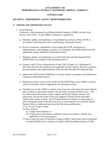
LOCATOR STANDARD AND EXTENDED RANGE MALESTHE MAGIC IS IN THE PIVOT, IT ALLOWS FOR A RESILIENT CONNECTIONOF THE PROSTHESIS AND PREVENTS DAMAGE TO MALES DURING INSERTION.STANDARD MALESEXTENDED RANGE MALESDual retention to maximize stability andpivoting action that accommodates upto 20 divergence between two implants.Pivoting action accommodates up to 40 of total divergence between two implants.Extra etentionExtra LightRetentionLightRetentionRegularRetention
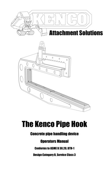
LOCATOR 3-IN-1 CORE TOOLThis convenient tool is used to carry the LOCATOR Abutment and place it onto the implant. It is also utilized forremoval and seating the Males from/into the Denture Cap. In order to achieve 30Ncm of torque, the AbutmentDriver portion of the tool is compatible with various types of restorative drivers.REMOVAL TOOLSEATING TOOLABUTMENT DRIVER & SLEEVEREMOVALSEATINGPLACEMENTThe Removal Toolhas a sharp edge on the end toengage and remove the Malefrom then Denture Cap.The Seating Toolis used to seat theLOCATOR Male.The Abutment Driverwith the Abutment HolderSleeve carries the Abutmentsecurely and places itonto the implant.USING THE CORE TOOLLoosen the Removal end of the Core Tool a full 3 turnscounter clockwise (you will see a visible gap).NOTE THE GAP ONCETURNED COUNTER CLOCKWISEREMOVING THE LOCATOR MALE FROM THEDENTURE CAP: Insert the tip into the Denture CapAssembly and push straight into the bottom of theMale. Tilt the tool so that the sharp edge of the tip willengage with the Male and pull it out of the DentureCap.DISENGAGING THE LOCATOR MALE FROM THE TIPOF THE CORE TOOL: Point the tool down and awayfrom you and tighten the Removal Tool clockwise backonto the Core Tool. This will activate the removal pin anddisengage the Male from the tip of the Removal Tool.PLACING THE LOCATOR MALE: Separate The RemovalTool section from the Core Tool and use the Seating Toolend to place a new Male into the empty Denture Cap.5
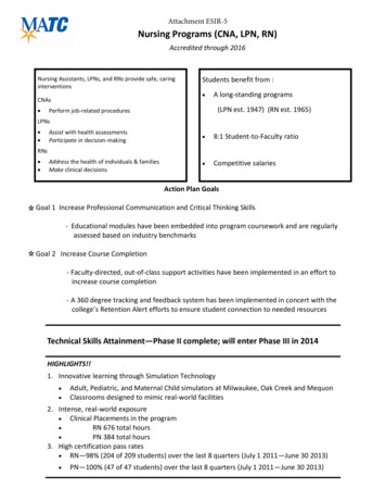
LOCATOR IMPLANT ATTACHMENT SYSTEMABUTMENT AND REPLACEMENT MALE SELECTION112A1Identify the system and diameter of each implant.Remove the healing abutments.2BCuff32A-2B Using a periodontal probe, measure theheight of the gingiva at the highest point and select thecuff height of the LOCATOR Abutment that correspondsto that measurement. If it is 2mm, choose a 2mm cuffheight. An additional 1.5mm of Abutment height willextend above the gingiva to accommodate for theDenture Cap.3 Use the Angle Measurement Guide to determinethe angulation of each implant. Select the LOCATORStandard Males for implants with 10 of divergenceor less; and the LOCATOR Extended Range Males forimplants with greater than 10 and less than 20 ofdivergence.NOTE: Please refer to the Standard and Extended RangeMale retention chart on page 4.6
LOCATOR IMPLANT ATTACHMENT SYSTEMABUTMENT PLACEMENT11Slide the Abutment Holder Sleeve onto the abutmentdriver portion of the LOCATOR 3-in-1 Core Tool. Place theLOCATOR Abutment selected for each implant into theAbutment Holder Sleeve.22 Screw the LOCATOR Abutment into the implant andhand tighten. Radiograph each interface to confirm thatthe Abutments are fully seated on the implants. Place thefilm perpendicular to the interface.33 Using a torque device and the LOCATOR DriverInsert, torque each LOCATOR Abutment to 30Ncm orto the torque for an abutment screw recommended bythe manufacturer of the implant/abutment system if thatrecommended torque is 35Ncm or less.NOTE: Implants with 1.4mm thread require theLOCATOR Abutment be torqued to 20Ncm.WARNING: Use of higher torque values thanrecommended could cause a fracture of the LOCATORAbutment.A direct or indirect technique may be used for processing the Denture Cap into the overdenture. Please refer topage 10 for Direct Technique and page 13 for Indirect Technique for the LOCATOR Implant Attachment System.7
LOCATOR MULTI-UNIT ABUTMENTSFREE STANDING APPLICATIONThe LOCATOR Abutment for the Multi-Unit Abutment is a two piece component that consists of a TitaniumCollar and a LOCATOR Abutment. The combined two pieces, used with a straight or angled Multi-UnitAbutment, is intended for Free Standing LOCATOR Attachment System applications.11 After the Multi-Unit Abutment (with the proper tissuecuff height) has been selected and torqued into theimplant, place the LOCATOR Titanium Collar onto it.22Hand-tighten the LOCATOR Abutments and torqueto 20Ncm (identified by “ M1.4” symbol on label) usinga LOCATOR Torque Wrench Driver for final torquetightening to prevent screw loosening.33 The use of higher torque values than the maximumrecommended 20Ncm could cause fracture of the MultiUnit LOCATOR Abutment. Proceed with the standardprocedure of the LOCATOR Attachment System.8
LOCATOR FOR BAR SPLINTED MULTI-UNITIMPLANT ABUTMENTSThe proper tissue cuff height of angled Multi-Unit Abutments and straight Multi-Unit Abutments must beplaced according to the Implant Company clinical procedures. The bar splinted LOCATOR Implant Abutmentfor the angled Multi-Unit Abutment and the straight Multi-Unit Abutment is a two piece part that contains acastable plastic Delrin Collar and the LOCATOR Abutment.12A1 Take an impression with the implant manufacturer MultiUnit Impression Copings and create a master model usingthe Multi-Unit Abutment Replicas.2B2A-2BOn the master model place a Delrin Collar oneach of the four Multi Unit Abutments. A special gold platedAbutment Driver (end piece of the LOCATOR Core Tool) isdesigned to engage the inside diameter of the LOCATORAbutment to place it through the Delrin Collar and thread itinto the internal thread of the Multi-Unit Abutment Analog.Wax the four Delrin Collars directly into the bar pattern. Remove the LOCATOR Abutments and cast the waxed bar pattern according to standard dentallaboratory procedures. After polishing the cast bar, place the bar and LOCATOR Abutments back onto the master model tocheck for proper fit. Seat the bar on the Multi-Unit Abutments and seat the LOCATOR Abutments through the cast barand onto the Multi-Unit Abutments. Hand-tighten the LOCATOR Abutments and torque to 20Ncm (identified by “ M1.4” symbol on label)using a LOCATOR Torque Wrench Driver for final torque tightening to prevent screw loosening. The use of higher torque values than the maximum recommended 20Ncm could cause fracture ofthe Multi-Unit LOCATOR Abutment. Proceed with the standard procedure of the LOCATOR Bar Attachment.9
PROCESSING LOCATOR DENTURE CAPS INTO THEOVERDENTURE, DIRECT TECHNIQUE1DIRECT TECHNIQUE FOR NEW OREXISTING DENTURE1Place a White Block-Out Spacer around eachAbutment and press it down to the tissue. Snap aDenture Cap with a pre-loaded Black Processing Maleonto each Abutment, pressing down firmly.22 Apply fit check marking paste to the intaglio surfaceof the overdenture. Insert it into the mouth in positionover the Denture Cap. This will mark areas where theoverdenture will need to be relieved to allow space forthe Caps to be picked up.3A3B4.5mm drillingdepth4A104B3A-3BRelieve the marked areas with theCHAIRSIDE Recess Bur. Zest recommends using slightpressure and a small rocking motion to get the tip of theBur started, followed by a straight downward motionto create the desired recess site. This efficient Bur hasdistinct depth landmarks which indicate where to stopwhen drilling for the Denture Cap.4A-4B Use the CHAIRSIDE Undercut Bur to cut anundercut around the circumference of the recesses formechanical retention. Cut lingual/palatal vent windowsin the overdenture with the CHAIRSIDE Vent Bur tovisualize full seating and for excess material to vent.
PROCESSING LOCATOR DENTURE CAPS INTO THEOVERDENTURE, DIRECT TECHNIQUE (CONTINUED)55 Dry the Denture Caps. Apply a small amount ofCHAIRSIDE Attachment Processing Material around thecircumference of each Cap. Place CHAIRSIDE Materialinto the recesses in the overdenture and seat it over theCaps and onto the tissue. Have the patient close intolight occlusion and hold while the CHAIRSIDE Materialsets. Please refer to CHAIRSIDE Attachment ProcessingMaterial IFU for set times.NOTE: Excessive occlusal pressure during the settingtime may cause tissue recoil against the overdenture baseand could contribute to dislodging and premature wearof the Males.66 Disengage the overdenture from the Abutments andremove fro
The LOCATOR Abutment for the Multi-Unit Abutment is a two piece component that consists of a Titanium Collar and a LOCATOR Abutment. The combined two pieces, used with a straight or angled Multi-Unit Abutment, is intended for Free Standing LOCATOR Attachment System applications. Hand-tighten the LOCATOR Abutments and torque