Transcription
12Fundamentals of Alternating CurrentIn this chapter, we lead you through a study of the mathematics and physics ofalternating current (AC) circuits. After completing this chapter you should be able to: Develop a familiarity with sinusoidal functions.Write the general equation for a sinusoidal signal based on its amplitude,frequency, and phase shift.Define angles in degrees and radians.Manipulate the general equation of a sinusoidal signal to determine its amplitude,frequency, phase shift at any time.Compute peak, RMS, and average values of voltage and current.Define root-mean-squared amplitude, angular velocity, and phase angle.Convert between time domain and phasor notation.Convert between polar and rectangular form.Add, subtract, multiply, and divide phasors.Discuss the phase relationship of voltage and current in resistive, inductive, andcapacitive loads.Apply circuit analysis using phasors.Define components of power and realize power factor in AC circuits.Understand types of connection in three-phase circuits.FOCUS ON MATHEMATICSThis chapter relates the application of mathematics to AC circuits, covering complexnumbers, vectors, and phasors. All these three concepts follow the same rules.REFERENCES Stephan J. Chapman, Electric Machinery Fundamentals, Third Edition, McGraw-Hill,1999.Stephan J. Chapman, Electric Machinery and Power System Fundamentals, McGrawHill, 2002.Bosels, Electrical Systems Design, Prentice Hall.James H. Harter and Wallace D. Beitzel, Mathematics Applied to Electronics,Prentice Hall.1
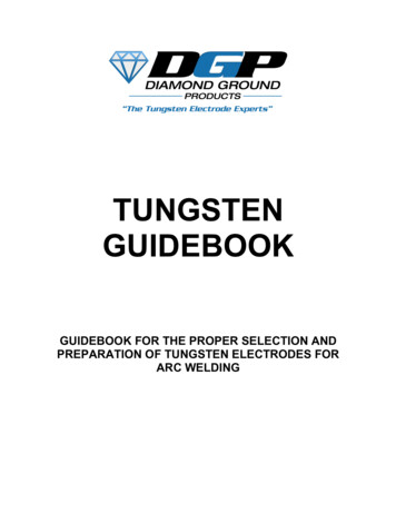
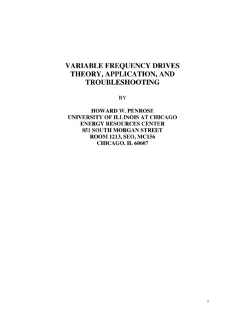
2Chapter 1212.1 INTRODUCTIONThe majority of electrical power in the world is generated, distributed, andconsumed in the form of 50- or 60-Hz sinusoidal alternating current (AC) andvoltage. It is used for household and industrial applications such as televisionsets, computers, microwave ovens, electric stoves, to the large motors used in theindustry.AC has several advantages over DC. The major advantage of AC is the factthat it can be transformed, however, direct current (DC) cannot. A transformerpermits voltage to be stepped up or down for the purpose of transmission.Transmission of high voltage (in terms of kV) is that less current is required toproduce the same amount of power. Less current permits smaller wires to be usedfor transmission.In this chapter, we will introduce a sinusoidal signal and its basicmathematical equation. We will discuss and analyze circuits where currents i(t)and voltages v(t) vary with time. The phasor analysis techniques will be used toanalyze electric circuits under sinusoidal steady-state operating conditions.Single-phase power will conclude the chapter.12.2 SINUSOIDAL WAVEFORMSAC unlike DC flows first in one direction then in the opposite direction. Themost common AC waveform is a sine (or sinusoidal) waveform. Sine waves arethe signal whose shape neither is nor altered by a linear circuit, therefore, it isideal as a test signal.In discussing AC signal, it is necessary to express the current and voltage interms of maximum or peak values, peak-to-peak values, effective values, averagevalues, or instantaneous values. Each of these values has a different meaning andis used to describe a different amount of current or voltage. Figure 12-1 is a plotof a sinusoidal wave. The correspondence mathematical form isv(t ) V p cos(wt θ )(12.1)Where Vp is the peak voltage, ω 2πf is the angular speed expressed inradians per second (rad/s), f is the frequency expressed in Hertz (Hz), t is the timeexpressed in second (s), and θ is phase of the sinusoid expressed in degrees.The function (Figure 12-1) starts at a value of 0 at 0o, and rise smoothly to amaximum of 1 at 90o. They then fall, just as they rose, back to 0o at 180o. Thenegative peak is reached three quarters of the way at 270o. The function thenreturns symmetrically to 0o at 360o.
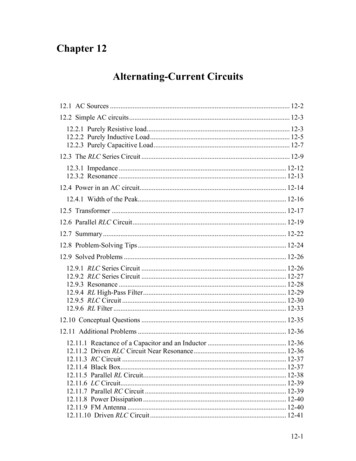
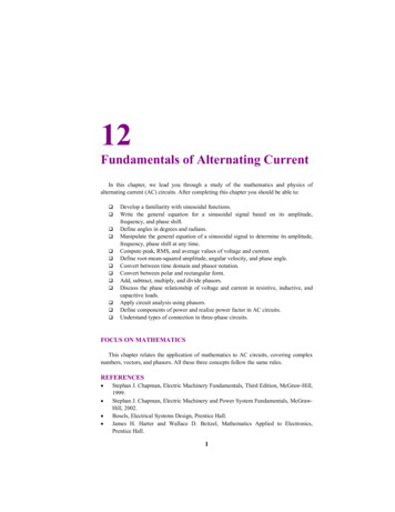
Fundamentals of Alternating Current3RMS valuePeak valuePeak-to-peak1 cycleFigure 12-1 Sinusoidal wave values.12.2.1 Radian and DegreeA degree is a unit of measurement in degree (its designation is or deg), a turnof a ray by the 1/360 part of the one complete revolution. So, the completerevolution of a ray is equal to 360 deg.A radian is defined as the central angle, for which lengths of its arc and radiusare equal (AB A0). An arc length is the distance along the arc of a circle fromthe origin to the end of the angle. These terms are shown in Figure 13-8.Following Equation (12.1), a length of a circumference C and its radius r canbe expressed as:2π CR(12.2)So, a round angle, equal to 360 in a degree measure, is simultaneously 2π ina radian measure. Hence, we receive a value of one radian:360 57.3o2π(12.3)2π 0.017453 rad360(12.4)1 rad and,1 deg
4Chapter 12The following comparative table of degree and radian provides measure forsome angles we often deal with:B0AFigure 12-2 Radian and arc length.Table 12-1 Angles in Degree and RadianAngle (deg)Angle (rad)0045π/490π/2180π2703π/23602π12.2.2 Peak and Peak-to-Peak ValuesDuring each complete cycle of AC signal there are always two maximum orpeak values, one for the positive half-cycle and the other for the negative halfcycle.The peak value is measured from zero to the maximum value obtained ineither the positive or negative direction.The difference between the peak positive value and the peak negative value iscalled the peak-to-peak value of the sine wave. This value is twice the maximumor peak value of the sine wave and is sometimes used for measurement of acvoltages. The peak value is one-half of the peak-to-peak value.12.2.3 Instantaneous ValueThe instantaneous value of an AC signal is the value of voltage or current atone particular instant. The value may be zero if the particular instant is the time inthe cycle at which the polarity of the voltage is changing. It may also be the sameas the peak value, if the selected instant is the time in the cycle at which thevoltage or current stops increasing and starts decreasing. There are actually aninfinite number of instantaneous values between zero and the peak value.
Fundamentals of Alternating Current512.2.4 Average ValueThe average value of an AC current or voltage is the average of all theinstantaneous values during one alternation. They are actually DC values. Theaverage value is the amount of voltage that would be indicated by a DC voltmeterif it were connected across the load resistor.Since the voltage increases from zero to peak value and decreases back to zeroduring one alternation, the average value must be some value between those twolimits. It is possible to determine the average value by adding together a series ofinstantaneous values of the alternation (between 0 and 180 ), and then dividingthe sum by the number of instantaneous values used. The computation wouldshow that one alternation of a sine wave has an average value equal to 0.636times the peak value. The formula for a average voltage isVav 0.636Vmax(12.5)Where Vav is the average voltage for one alteration, and Vmax is the maximumor peak voltage. Similarly, the formula for average current isI av 0.636 I max(12.6)Where Iav is the average current for one alteration, and Imax is the maximum orpeak current.12.2.5 Effective ValueThis is the value of AC signal that will have the same effect on a resistance asa comparable value of direct voltage or current will have on the same resistance.It is possible to compute the effective value of a sine wave of current to a gooddegree of accuracy by taking equally spaced instantaneous values of currentalong the curve and extracting the square root of the average of the sum of thesquared values. For this reason, the effective value is often called the “root-meansquare” (RMS) value. Therefore,I eff Average of the sum of the squares of I ins(12.7)The effective or rms value (Ieff) of a sine wave of current is 0.707 times themaximum value of current (Imax). Thus, I eff 0.707 Imax. When I eff is known, wemay find Imax by using the formula Imax 1.414 Ieff. We might wonder where theconstant 1.414 comes from. To find out, examine Figure and read the followingexplanation. Assume that the DC in Figure is maintained at 1 A and the resistor
6Chapter 12temperature at 100 C. Also assume that the AC in Figure is increased until thetemperature of the resistor is 100 C. At this point it is found that a maximum ACvalue of 1.414 A is required in order to have the same heating effect as DC.Therefore, in the AC circuit the maximum current required is 1.414 times theeffective current.When a sinusoidal voltage is applied to a resistance, the resulting current isalso a sinusoidal. This follows Ohm’s law which states that current is directlyproportional to the applied voltage. Ohm’s law, Kirchhoff’s law, and the variousrules that apply to voltage, current, and power in a DC circuit also apply to theAC circuit. Ohm’s law formula for an AC circuit may be stated asI eff VeffR(12.8)Importantly, all AC voltage and current values are given as effective values.12.2.6 FrequencyIf the signal in the Figure makes one complete revolution each second, thegenerator produces one complete cycle of AC during each second (1 Hz).Increasing the number of revolutions to two per second will produce twocomplete cycles of ac per second (2 Hz). The number of complete cycles ofalternating current or voltage completed each second is referred to as the“frequency, f” or “event frequency”. Event frequency is always measured andexpressed in hertz. Because there are 2π radians in a full circle, a cycle, therelationship between ω, f, and period, T, can be expressed asω 2πf 2πradians/secondT(12.9)Where ω is the angular velocity in radians per second (rad/s). The dimensionof frequency is reciprocal second. The frequency is an important term tounderstand since most AC electrical equipment requires a specific frequency forproper operation.
Fundamentals of Alternating Current7Example 12-1Express each of the following frequencies in Hertza)b)c)d)40 cycles in 4.0 seconds80 cycles in 200 milliseconds1000 revolutions in 0.5 seconds600 rotations in 1 minuteSolution:a)b)c)d)40/4.0 10 cycles per second 10 Hz80/0.2 400 cycles per second 400 Hz1000/0.5 2000 cycles per second 4000 Hz (4 kHz)600/60 10 cycles per second 10 HzExample 12-2Express each of the following as angular velocity in radians per seconda)b)c)d)80 rad in 10 s2.5 krad in 50 s400 rad in 200 s40 Mrad in 10 sSolution:a)b)c)d)ω 80/10 8 rad/sω 2500/50 500 rad/sω 400/200 2.0 rad/sω (40 106)/10 4.0 rad/sExample 12-3Express each of the following frequencies as angular velocity in radians perseconda)b)c)d)60 Hz500 Hz10 kHz1 MHz
8Chapter 12Solution:a)b)c)d)ω 2π 60 377 rad/sω 2π 500 3141.5 rad/sω 2π (10 103) 62.83 krad/sω 2π (1.0 106) 6.28 Mrad/s12.2.7 PeriodThe period of a waveform is the time required for completing one full cycle. Itis measured in seconds. In Figure 15-1, the sinusoidal waveform is plotted as afunction of the argument ωt, and the periodic nature of the sine wave is evident.The function repeats itself every 2π radians, and its period is therefore 2π radians.The relationship between time (T) and frequency (f) is indicated by the formulasT 1f(12.10)Example 12-4Express each of the following periods in secondsa)b)c)d)500 Hz90 kHz900 MHz5 HzSolution: Use Equation (12.10)a)b)c)d)T 2 msT 1/(90 103) 11.11 µsT 1/(900 106) 1.11 psT 0.2 s12.2.8 PhaseWhen two sinusoidal waves, such as those represented by Figure 12-3, areprecisely in step with one another, they are said to be in phase. To be in phase,
Fundamentals of Alternating Current9the two waves must go through their maximum and minimum points at the sametime and in the same direction.To further describe the phase relationship between two sinusoidal waves, theterms lead and lag are used. The amount by which one sine wave leads or lagsanother sine wave is measured in degrees. According to Figure 12-3, the sinusoidVP sin (ωt θ) occur θ rad, θ degrees seconds, earlier. In this case we say VP sin(ωt θ) leads VP sin ωt by θ. Also, we may say that VP sin ωt lags VP sin (ωt θ)by θ.In general, it is possible for one sine wave to lead or lag another sine wave byany number of degrees, except 0 or 360 . When the latter condition exists, thetwo waves are said to be in phase. Thus, two sine waves that differ in phase by45o, for example, are actually out of phase with each other, whereas two sinewaves that differ in phase by 360 are considered to be in phase with each other.To determine the phase difference between two sine waves, locate the pointson the time axis where the two waves cross the time axis traveling in the samedirection. The number of degrees between the crossing points is the phasedifference. The wave that crosses the axis at the later time (to the right on thetime axis) is said to lag the other wave.12.2.9 Sine and CosineThe sine and cosine are essentially the same function, but with a 90o phasedifference. For example, sin ω t cos (ωt – 90o). Multiples of 360o may be addedto or subtracted from the argument of any sinusoidal function without changingthe value of the function. To realize this, let us considerv1 VP1 cos (10t 20 o ) VP1 sin (10t 90 o 20 o )(12.11) VP1 sin (10t 110 o )leadsv2 VP2 sin (10t - 40 o )(12.12)by 150o. It is also correct to say that v1 lags v2 by 210o, since v1 may be written asv1 VP1 sin (10t - 250 o )(12.13)
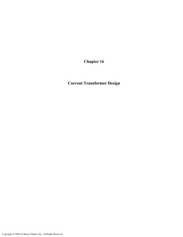
10Chapter 12vVPVP sin ωtVP sin (ωt θ)ωtθ-VPFigure 12-3 The sine wave VP sin (ωt θ) leads VP sin ωt.12.3 PHASORSWe have learnt from the previous section how to define and express in a singleequation the magnitude, frequency, and phase shift of a sinusoidal signal. Anylinear circuit that contains resistors, capacitors, and inductors do not alter theshape of this signal, nor its frequency. However, the linear circuit does change theamplitude of the signal (amplification or attenuation) and shift its phase (causingthe output signal to lead or lag the input). The amplitude and phase are the twoimportant quantities that determine the way the circuit affects the signal.Accordingly, signal can be expressed as a linear combination of complexsinusoids. Phase and magnitude defines a phasor (vector) or complex number.The phasor is similar to vector that has been studied in mathematics.Figure 12-4 shows how AC sinusoidal quantities are represented by theposition of a rotating vector. As the vector rotates it generates an angle. Thelocation of the vector on the plane surface is determined by the magnitude(length) of the vector and by the generated angle.Representing sinusoidal signals by phasors is useful since circuit analysis lawssuch as KVL and KCL and familiar algebraic circuit analysis tools, such as seriesand parallel equivalence, voltage and current division are applicable in the phasordomain, which have been studied in DC circuits can be applied. We do not neednew analysis techniques to handle circuits in the phasor domain. The onlydifference is that circuit responses are phasors (complex numbers) rather than DCsignals (real numbers).In order to work with these complex numbers without drawing vectors, wefirst need some kind of standard mathematical notation. There are two basicforms of complex number notation: polar and rectangular.
Fundamentals of Alternating Current113234495162195677(a)(b)Figure 12-4 (a) Magnitude of a sine wave. (b) A vector with its end fixed at theorigin and rotating in a counterclockwise (CCW) direction representing thevarying conditions of the AC signal.12.3.1 Polar FormPolar form is where the length (magnitude) and the angle of its vector denote acomplex number. Standard orientation for vector angles in AC circuitcalculations defines 0o as being to the right (horizontal), making 90o straight up,180o to the left, and 270o straight down. Vectors angled “down” can have anglesrepresented in polar form as positive numbers in excess of 180 or negativenumbers less than 180 (Figure 12-5). For example, a vector angled 270o(straight down) can also be said to have an angle of -90o.90o180o0o270oFigure 12-5 Standard orientation for vector angles.
12Chapter 12(b)(a)Figure 12-6 (a) A vector (5.4 326o) (b) A vector 5.4 -34o.A vector quantity has both magnitude and direction. Figure 12-6a shows avector with positive angle (5.4 326o), while Figure 12-6b shows a vector (5.4 -34o) with negative angle.In electrical circuits, a sinusoidal voltage may be represented byV Vrms θ(12.14)Where the uppercase V, indicates that the quantity is a phasor, having bothmagnitude and phase. The magnitude is usually RMS. The phase angle is indegrees. The polarity is very important: means that the signal leads thereference; while – means that the signal lags the reference.Example 12-5Write the phasor form for the following signal and draw the phasor diagram. Usea scale of 1 cm 100 Vrms.(v 300 V p sin 377t- 45oSolution:VpVrms 2300 212.16 V2V 212.16 - 45oThe phasor diagram is shown in Figure 12-7.)
Fundamentals of Alternating Current13-45oFigure 12-7 Phasor diagram of Example 12-5.12.3.2 Rectangular FormThe horizontal and vertical components denote a complex number. The angledvector is taken to be the hypotenuse of a right triangle, described by the lengths ofthe adjacent and opposite sides. These two dimensional figures (horizontal andvertical) are symbolized by two numerical figures. In order to distinguish thehorizontal and vertical dimensions from each other, the vertical is prefixed with alower-case “i” (in pure mathematics) or “j” (in electronics). Figure 12-8 showsthat a point on a complex plane located by a phasor could be described inrectangular form. Imaginary4 j35 Real-Real-ImaginaryFigure 12-8 A point on the complex plane located by the phasor 4 j3 expressedin the rectangular form.
14Chapter 12Focus on MathematicsComplex AlgebraA complex number is the sum of a real number and an imaginarynumber [A Real (A) j Imaginary (A)]. We know what realnumbers are since we use them very often. What are imaginarynumbers? The answer to this question is related to another question.What is the square root of minus one ( 1 )? The answer is j! Anynumber of the form j is called imaginary number. Sometimes, theletter i is used to define the imaginary number. Electrical engineersuse j because i is used for instantaneous current.Example 12-6Express 16 as an imaginary number.Solution: Write 16 - 1 16Replace 1 with j, then 16 j 415.3.3 Transforming FormsConsider the triangle in Figure 12-9. The hypotenuse is labeled as C. Theangle is θ. A represents the real value and B represents the imaginary value of therectangular form.V C θ A jB(12.15)
Fundamentals of Alternating Current15CBAFigure 12-9 Relation between polar and rectangular forms.To convert from the polar to the rectangular form of a phasor, you mustconvert C θ into A and B. From trigonometry, the cosine of an included anglerelates the length of the adjacent side and the length of the hypotenuse.AAdjacent Hypotenuse CBOppositesin θ Hypotenuse Ccos θ (12.16)To convert from rectangular form to polar form requires a different set oftrigonometric relationships.C A2 B 2Btan θ A(12.17)Taking the inverse tangent of each side leaves θ as B A θ tan -1 (12.18)In general, any load in rectangular form may be converted into polar form asthe followingZ R jX L X 2Z R 2 X L tan 1 L R (12.19)
16Chapter 12Example 12-7Convert each of the following polar phasors into their rectangular form.a)V 100 Vrms 60 o , andb)V 100 Vrms - 60 oSolution:a)b)V 50 Vrms j 86.6 VrmsV 50 Vrms - j 86.6 VrmsExample 12-8Convert each of the following polar phasors into their rectangular form.a)V 2 Vrms 45ob)V 240 Vrms - 160 oSolution:a)b)V 1.414 Vrms j 1.414 VrmsV - 225.526 Vrms - j 82.084 Vrms12.3.4 Euler’s IdentityEuler’s identity forms the basis of phasor notation. It is named after the Swi
Fundamentals of Alternating Current 3 Figure 12-1 Sinusoidal wave values. 12.2.1 Radian and Degree A degree is a unit of me