Transcription
TIC28x Digital Power Supply WorkshopWorkshop Guide and Lab ManualC28xdpsRevision 1.1May 2008Technical TrainingOrganization
Workshop TopicsImportant NoticeTexas Instruments and its subsidiaries (TI) reserve the right to make changes to their products or todiscontinue any product or service without notice, and advise customers to obtain the latest version ofrelevant information to verify, before placing orders, that information being relied on is current andcomplete. All products are sold subject to the terms and conditions of sale supplied at the time of orderacknowledgment, including those pertaining to warranty, patent infringement, and limitation of liability.TI warrants performance of its semiconductor products to the specifications applicable at the time of sale inaccordance with TI’s standard warranty. Testing and other quality control techniques are utilized to theextent TI deems necessary to support this warranty. Specific testing of all parameters of each device is notnecessarily performed, except those mandated by government requirements.Customers are responsible for their applications using TI components.In order to minimize risks associated with the customer’s applications, adequate design and operatingsafeguards must be provided by the customer to minimize inherent or procedural hazards.TI assumes no liability for applications assistance or customer product design. TI does not warrant orrepresent that any license, either express or implied, is granted under any patent right, copyright, maskwork right, or other intellectual property right of TI covering or relating to any combination, machine, orprocess in which such semiconductor products or services might be or are used. TI’s publication ofinformation regarding any third party’s products or services does not constitute TI’s approval, warranty orendorsement thereof.Copyright 2008 Texas Instruments IncorporatedRevision HistoryJanuary 2008 – Revision 1.0May 2008 – Revision 1.1Mailing AddressTexas InstrumentsTraining Technical Organization7839 Churchill WayM/S 3984Dallas, Texas 75251-19032C28x Digital Power Supply Workshop
Workshop TopicsWorkshop TopicsWorkshop Topics.3Workshop Outline .41 – Introduction to Digital Power Supply Design.5What is a Digital Power Supply?.5Why use Digital Control Techniques?.6Peripherals used for Digital Power Supply Design.10Development Tools and Software .12Lab1: Exploring the Development Environment.162 – Driving the Power Stage with PWM Waveforms .24Open-Loop System Block Diagram.24Generating PWM using the ePWM Module.25Power Stage Topologies and Software Library Support.28Lab2: PWM Generation / Open-Loop Control .323 – Controlling the Power Stage with Feedback.42Closed-Loop System Block Diagram .42ADC Module Block Diagram.43Digital Control of Power Converter .43High-Resolution PWM Benefits.46Soft Start – Starting the Loop .47Lab3: Closed-Loop Control .484 – Tuning the Loop for Good Transient Response .57Digital Power Supply Control Theory .57Intuitive Loop Tuning – “Visually without Math” .59Active Load Feature of the Power EVM .63Lab4: Tuning the Loop.64Multi-Loop Control .715 – Summary and Conclusion .73Review of Workshop Topics and Exercises .73TI Digital Power Products .74C2000 Digital Signal Controller Family.75UCD9xxx Digital Power Controller Family .80Where to Find More Information .81C28x Digital Power Supply Workshop3
Workshop OutlineWorkshop OutlineWorkshop Outline1.Introduction to Digital PowerSupply Design 2.Driving the Power Stage with PWMWaveforms 3.4Lab: Closed-Loop ControlTuning the Loop for Good TransientResponse 5.Lab: PWM Generation / Open-Loop ControlControlling the Power Stage withFeedback 4.Lab: Exploring the Development EnvironmentLab: Tuning the LoopSummary and ConclusionC28x Digital Power Supply Workshop
1 – Introduction to Digital Power Supply Design1 – Introduction to Digital Power Supply DesignIntroduction to Digital Power Supply Design What is a Digital Power Supply?Why use Digital ControlTechniques?Peripherals used for Digital PowerSupply DesignDevelopment Tools and SoftwareWhat is a Digital Power Supply?What is Digital Power?Generic Power System Block LCNetworkVoutThe controller block is what differentiates between a digitalpower system and a conventional analog power systemC28x Digital Power Supply Workshop5
1 – Introduction to Digital Power Supply DesignWhy use Digital Control Techniques?Why Digital Control Techniques?ControllerPower Elec.PWMAnalogorDigital ?Sensor(s)Analog Controller Digital Controller High bandwidthHigh resolution Easy to understand / use Historically lower cost Component drift and aging / unstableComponent tolerances Hardwired / not flexible Limited to classical control theory only Large parts count for complex systems Insensitive to environment (temp, drift, )S/w programmable / flexible solutionPrecise / predictable behavior Advanced control possible (non-linear, multi-variable) Can perform multiple loops and “other” functions Bandwidth limitations (sampling loop)PWM frequency and resolution limits Numerical problems (quantization, rounding, ) AD / DA boundary (resolution, speed, cost) CPU performance limitations Bias supplies, interface requirementsBenefits of Digital DCVI8451VVIMulti-modeMulti-modePower CU)(MCU?)OutputTraditional AnalogPower PFC pingCircuitsCircuits Multiple chips forcontrol Micro-controller forsupervisory Dedicated designTo HostAux P/SEliminate ComponentsFilterBridgeVPFCDC/DCVOutputReduce Manufacturing CostBetter Performance Across CornersOne Design, Multiple SuppliesFailure PredictionAux P/SDigital controller enables multi-threaded applications6One Device, Multiple DC OutputsVariable DC OutputC28x Digital Power Supply Workshop
1 – Introduction to Digital Power Supply DesignAnalog Control SystemR Σ-“Analog Computation”Differential eElementsRR2RR1C ( s) Ld 3 y (t )d 2 y (t )dy(t ) k2 k1 k 0 y (t ) f (t )3dtdt 2dtR2 1 R1C1s R1 1 R2C2 s Differential equations1st, 2nd, 3rd, orderNeed to find:R1, R2, C1, C2Laplace TransformDigital Control SystemR Σ-ECdU(controller)D-APZOH(plant)YA-DS&HDifference equationCU(n) a2 U(n 2) a1 U(n 1) Rb2 E(n 2) b1 E(n 1) b0 E(n)LwhereK E(n) R(n) Y (n)Need to find:a1, a2, b0, b1, b2d 3 y (t )d 2 y (t )dy(t ) k2 k1 k 0 y (t ) f (t )3dtdt 2dtDifferential equations1st, 2nd, 3rd, orderORC28x Digital Power Supply WorkshopEnergyStorageElementsLaplace TransformZ Transform7
1 – Introduction to Digital Power Supply DesignTime Sampled SystemsDigital Processor-A-D time signalu(n)u(t)tttDiscretetime signalProcessor Bandwidthy(n)TSAMPLEtProcessorControl CodeSam ple Freq ( PW M)(kHz )1003005007001000150020008Control CodeControlSa mple Period(ns )100003333200014291000667500C28x Digital Power Supply Workshop
1 – Introduction to Digital Power Supply DesignTime Division Multiplexing (TDM)y(n)TSAMPLEtProcessor 1Control Code (C1)Processor 2 Control Code (C2)Processor 3Single CPUControl Code (C3)C1C2C3Control CodeControl CodeControlControl CodeC1C2ControlControlC3C1C2C3Digitally Controlled Power C28x Digital Power Supply Workshop“Plant”“High fidelity”Translation boundary9
1 – Introduction to Digital Power Supply DesignSystem MappingPFC – 3ph InterleavedF280xxDSPCh1Ch2ADC32 bit core60 100MHzVO UTVin12 bit(80nS)Ch161AePWM11BPhase-Shifted Full Bridge2AePWM22B3AePWM3V OUTVIN3B8AePWM88BPeripherals used for Digital Power Supply DesignTMS320F280xHigh Performance DSP (C28xCode security 64Kw Flash 1Kw OTP18KwRAM4KwBootROM ePWMeCAPMemory BusTM100 MIPs C28x 32-bit DSP32x32-bitMultiplier32-bitTimers (3)Real-TimeJTAGR M WAtomicALUPeripheral BusInterrupt ManagementeQEP12-bit ADCWatchdog Core)100MIPS performanceSingle cycle 32 x32-bit MAC (or dual 16 x16 MAC)Very Fast Interrupt ResponseSingle cycle read-modified-writeMemory Sub-SystemFast program execution out of both RAM andFlash memory 85 MIPS with Flash Acceleration Technology 100 MIPS out of RAM for time-critical codeControl PeripheralsCAN 2.0 BI2CSCI32-bitRegisterFile TMSPIUp to 6 ePWM, 4 eCAP, and 2 eQEPUltra-Fast 12-bit ADC 6.25 MSPS throughput Dual sample&holds enable simultaneous sampling Auto Sequencer, up to 16 conversions w/o CPUCommunications PortsGPIOMultiple standard communication ports providesimple interfaces to other componentsDatasheet available at: http://www-s.ti.com/sc/ds/tms320f2808.pdf10C28x Digital Power Supply Workshop
1 – Introduction to Digital Power Supply DesignEfficient 32-bit Processor CapabilityC28xTM DSP CoreInterrupt ManagementC28xTM Single-cycle 32-bit multiplier makescomputationally intensive controlalgorithms more efficient Three 32-bit timers support multiplecontrol loops / time bases Single cycle read-modified-write in anymemory location and 32-bit registersimprove control algorithm efficiency Real-time JTAG debug shortensdevelopment cycle Fast & flexible interrupt managementsignificantly reduce interrupt latency32-bit DSP32x32 bitMultiplierR M WAtomicALU32-bitTimers (3)32-bitRegisterFileReal-TimeJTAG# Instructions vs PWMPWM freq. PWM per. Processor 1.313320010001.0100150TPWMPWMCPUControl Code spare Control Code spareControlMIPS Million Instruction Per SecondePWM “DAC” seControl PeripheralsEventTrig.& Int.TripZoneDeadBandPWMChopEPWMxAEPWMxBPWM effective resolution (CPU 100MHz)PWM(kHz)501001502505007501000Standard 756.61.00C28x Digital Power Supply 4.70.003713.70.007513.10.011212.70.0150ePWM Number of channels scalableand resources allocated perchannel Two independent PWM outputsper module Dedicated time-base timer Two independent compareregisters Multi-event driven waveform Trip zones and event interrupts F2808 offers 6 modules Provides ePWM DAC capabilityfor DPS Switching can be programmedas Asymmetric or SymmetricPWM High-Resolution PWM mode11
1 – Introduction to Digital Power Supply Design12-bit ADC CapabilityADCSYSCLKPrescaler8 ADCInputsAnalogMUX8 ADCInputsAnalogMUXS/HA12-bitADCModuleS/HBStart ofConversionResultRegisters16 wordsControl PeripheralsFast & Flexible12-bit 16-Channel ADC 12.5 MSPS throughput Dual sample/hold enablesimultaneous sampling orsequencing sampling modesAuto Sequencer Analog input: 0V to 3VADC Utilization:# Channels (“Loops”) vs. PWM frequencyMSPS 3PWM# Channels(kHz)12524250125006750410003MSPS 6.25PWM# Channels(kHz)125502502550013750810006 16 channel, multiplexed inputs Auto Sequencer supports up to 16conversions without CPUintervention Sequencer can be operated as twoindependent 8-state sequencers oras one large 16-state sequencer Sixteen result registers (individuallyaddressable) to store conversionvaluesDevelopment Tools and SoftwareCode Composer StudioMenus or IconsHelpCPUWindowProject Manager:¾Source & object files¾File dependencies¾Compiler, Assembler &Linker build optionsFull C/C & AssemblyDebugging:¾C & ASM Source¾Mixed mode¾Disassembly (patch)¾Set Break Points¾Set Probe ch WindowGraphWindowMemory WindowC28x Digital Power Supply Workshop
1 – Introduction to Digital Power Supply DesignSoftware Library ApproachCNTL2P2ZCNTL3P3ZRefRefUoutFBControl 2-pole / Control 3-pole / 3-zeroEPWMnADutyBuck Single OutputIIR-FILT2P2ZIIR-FILT3P3ZfInMPILDRVfOutIn2nd order IIR WSGenHP1FreqF reqGainOutHHBDRVGainOffsetOutDutyOffsetSine Wave generatorHigh precision Sine GenIBMFBDRVEPWMHWEPWMnAInEPWMnBD elLLD elRLHalf H-BridgeINVSQ RPSFBDRVOutDelayEPWMPhaseSlopeInverse Square functionEPWMEPWMnAHWEPWMnBEPWMHWEPWMnAEPWMnBEPWM(n 1)AEPWM(n 1)BIBM method Full BridgeSSartSEQInEPWMnAPower Factor 2-phaseInterleavedMulti-Phase InterleavedSinGen1HWHigh Resolution BuckEPWM2BDuty3rd order IIR filterEPWMOutLlegdbT argetRlegdbSoft Start and SequencingHWEPWMnAADCDRVEPWMnBEPWM(n 1)ARsltEPWM(n 1)BADCCh0Ch1Ch3Ch4HWAnalog-Digital Converter driverPhase Shifted Full BridgeModular Software Architecture“Signal Net” based module connectivityNet1In 1ANet2In 1Bf1O ut1Net6f2Net3In 2AIn 3ANet7In4AIn4BOut4Net8f5In5AOut5Net9O ut3Initialization time// pointer & Net declarationsInt *In1A, *In1B, *Out1, *In2A,.Int Net1, Net2, Net3, Net4,.// “connect” the modulesIn1A &Net1; In1B &Net2; In2A &Net3; In3A &Net4; // inputsOut4 &Net8; Out5 &Net9;// outputsOut1 &Net5; In4A &Net5;// Net5Out2 &Net6; In4B &Net6;// Net6Out3 &Net7; In4C &Net7; In5A &Net7;// Net7C28x Digital Power Supply Workshopf4In4CO ut2f3Net4Net5Run time - ISR; Execute the codef1f2f3f4f513
1 – Introduction to Digital Power Supply DesignPeripheral DriversCPU dependency only: Math / algorithms Per-Unit math (0-100%) Independent of EQ1DRVVoutRslt0(Q15)EPWMHWIn(Q15)ADCHW// pointer & Net declarationsint *CNTL Ref1, *CNTL Fdbk1, *CNTL Out1;int *BUCK In1, *ADC Rslt1;int Vref, Duty, Vout;Depends on: PWM frequency System clock frequencyEPWM1AADC A0ADC A1ADC A2ADC A3Depends on: # ADC bits (10 / 12 ?) Unipolar, Bipolar ? Offset ?// “connect” the modulesCNTL Ref1 &Vref;CNTL Out1 &Duty; BUCK In1 &Duty;CNTL Fdbk1 &Vout; ADC Rslt1 &Vout;Dual Buck ExampleBGISRStart / Stop triggerVoltag eContro llerS-start / SEQV ref1CNTL2P2ZRefFBUoutDutyCmd 1BUCKDRVEPWMDutyHWSingle Power StageVinEPWM1AVout1DRVB uck400 kHz400 kHzADCDRVVout1rslt0ADCHWCh0400 kHzVoltag eContro llerS-start / SEQV ref2CNTL2P2ZRefUoutDutyCmd 2FBBUCKDRVEPWMDutyHWSingle Power StageVinEPWM2AVo ut2DRVB uck400 kHz400 kHzADCDRVVout2rslt0ADCHWCh1400 kHz14C28x Digital Power Supply Workshop
1 – Introduction to Digital Power Supply DesignSoftware Block ExecutionBGISR(400 kHz)SStartSeqContext SaveCommsADC DRV (1)CNTL 2P2Z(1)Loop-1BUCK DRV (1)ISR bodyADC DRV (2)CNTL 2P2Z(2)Loop-2Other.BUCK DRV (2)ContextRestoreC28x Digital Power Supply Workshop15
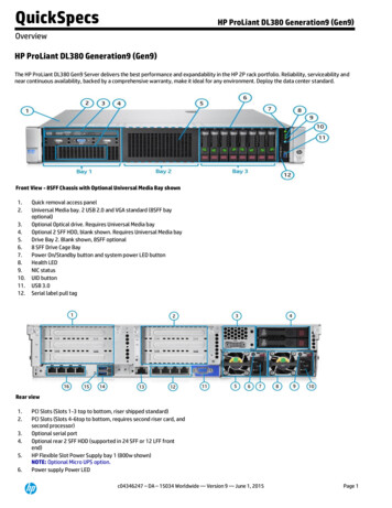
Lab1: Exploring the Development EnvironmentLab1: Exploring the Development Environment¾ ObjectiveThe objective of this lab exercise is to demonstrate the topics discussed in this module andbecome familiar with the operation of Code Composer Studio (CCS). Steps required to build andrun a project will be explored. The project will generate various PWM waveforms which will beviewed using the CCS graphical capabilities. The slider feature in CCS will be used to adjust theduty, phase, and dead-band values of the waveforms. Additionally, the Digital Power softwareframework, associated files, and library modules will be used.Lab1: Exploring the Development Environment Navigate CCS featuresUnderstand DPS library structureGenerate and visualize PWM waveforms TI PowerTrainPTD08A010W10A moduleSW1Phase LinksCurrent meas.Temp measOver Current Prot.Over Current FlagNo Heat-sink neededActiveLoad LEDsVoltMetercontrolCard 2808¾ Project OverviewThe PWMexplore project makes use of the “C-background/ASM-ISR” framework. Thisframework will be used throughout all the lab exercises in this workshop. It uses C-code as themain supporting program for the application, and is responsible for all system management tasks,decision making, intelligence, and host interaction. The assembly code is strictly limited to theISR, which runs all the critical control code and typically this includes ADC reading, controlcalculations, and PWM updates.The key framework C files used in this project are:PWMexplore-Main.c – this file is used to initialize, run, and manage the application. This isthe “brains” behind the application.PWMexplore-DevInit.c – this file is responsible for a one time initialization andconfiguration of the F280x device, and includes functions such as setting up the clocks, PLL,GPIO, etc.16C28x Digital Power Supply Workshop
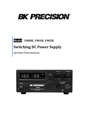
Lab1: Exploring the Development EnvironmentThe ISR consists of a single file:PWMexplore-ISR.asm – this file contains all time critical “control type” code. This file hasan initialization section (one time execute) and a run-time section which executes (typically) atthe same rate as the PWM timebase used to trigger it.The Power Library functions (modules) are “called” from this framework. Library modules mayhave both a C and an assembly component. In this lab exercise, six library modules (all PWMwaveform generators or drivers) are used. The C and corresponding assembly module names are:C configure functionASM initialization macroASM run-time macroBuckSingle CNF()BuckSingle DRV INIT nBuckSingle DRVBuckDual CNF()BuckDual DRV INIT nBuckDual DRVMPhIL CNF()MPhIL DRV INIT n, NMPhIL DRVFullBridgePS CNF()FullBridgePS DRV INIT nFullBridgePS DRVnnn, NnFullBridgeIBM CNF() FullBridgeIBM DRV INIT nFullBridgeIBM DRV nPFC2PhIL CNF()PFC2PhIL DRV INIT nPFC2PhIL DRV INIT nThese blocks can also be represented graphically. This helps visualize the system software flowand function input/output. The PWM driver modules used in Lab1 are:C28x Digital Power Supply Workshop17
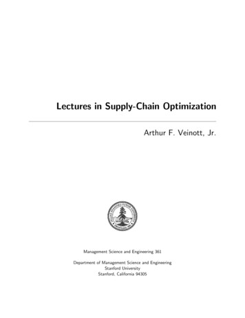
Lab1: Exploring the Development Environment¾ Lab Exercise OverviewThe software in Lab1 has been configured so the user can quickly evaluate the 6 PWM drivermodules by viewing the output waveforms and interactively adjusting the duty, phase, anddeadband values. The graphing feature of CCS is used to visualize the waveform. The ADCperipheral is configured to provide a “scope” capture function. The PWM outputs on the buckEVM are directly connected to ADC inputs via zero ohm resistors. Collected data samples arestored in four separate memory buffers, hence a simple 4-channel scope is realized. CCS can linkeach memory buffer to a graph window and display the captured data. With the real-time featureenabled, this data can be captured at high speed and streamed back via JTAG (at a slower rate) toupdate the graph windows periodically ( 200 ms update rate).Since the PWM waveforms being sampled are essentially “square waves” (high speed edges) theyhave been scaled down in frequency to approximately 10 kHz. This allows the ADC sampling tobetter capture and display the edge transitions in the graph window during datalogging. As Lab1is more for visual demonstration purposes, the high speed ISR code subroutine ISR Run hasbeen allocated to datalogging. The PWM driver macros are running at a much slower update ratefrom subroutine ISR Pseudo, which is conveniently called directly from C. The PWM drivermacro instantiation convention however is still the same as in the more typical case whereISR Run is used to execute all PWM updates and loop control. This will be the conventionused in Labs 2, 3 and 4 where an actual 2-channel buck stage will be controlled with high speedPWM outputs.The following diagram shows an example of how the Full Bridge Phase Shifted PWM module isevaluated in this lab. This setup is essentially the same for all 6 cases, except the PWM drivermacro module is swapped and the appropriate sliders used to adjust the relevant timing areselected.18C28x Digital Power Supply Workshop
Lab1: Exploring the Development Environment¾ ProcedureStart CCS and Open a Project1. Move the switch SW1 to the “on” position to power the 2-channel buck EVM board.2. Double click on the Code Composer Studio icon on the desktop. Maximize CodeComposer Studio to fill your screen. Code Composer Studio has a Connect/Disconnectfeature which allows the target to be dynamically connected and disconnected. This willreset the JTAG link and also enable “hot swapping” a target board. Connect to the target.Click: Debug Æ ConnectThe menu bar (at the top) lists File . Help. Note the horizontal tool bar below the menubar and the vertical tool bar on the left-hand side. The window on the left is the projectwindow and the large right hand window is your workspace.3. A project contains all the files and build options needed to develop an executable outputfile (.out) which can be run on the DSP hardware. A project named Lab1.pjt hasbeen created for this lab exercise. Open the project by clicking:Project Æ Open and look in C:\C28x DPS\LABS\LAB1. This project (.pjt file) will invoke all thenecessary tools (compiler, assembler, linker) to build the project. It will also create afolder that will hold immediate output files.4. In the project window on the left, click the plus sign ( ) to the left of Project. Now,click on the plus sign next to Lab1.pjt. Click on the plus sign next to Source to seethe current source file list.5. A GEL file can be used to create a custom GEL menu and automate steps in CCS. AGEL file which will setup sliders has been created for this lab exercise. The slider will beused to adjust the duty, phase, and dead-band values of the waveforms. Load thePWMexplore.gel file by clicking:File Æ Load Gel and look in C:\C28x DPS\LABS\LAB1.Device Initialization, Main, and ISR FilesNote: DO NOT make any changes to the source files – ONLY INSPECT6. Open and inspect PWMexplore-DevInit.c by double clicking on the filename in theproject window. Notice that system clock, peripheral clock prescale, and peripheralclock enables have been setup. Next, notice that the shared GPIO pins have beenconfigured.C28x Digital Power Supply Workshop19
Lab1: Exploring the Development Environment7. Open and inspect PWMexplore-Main.c. Notice the background for(;;) loop andthe case statements. This is where each of the PWM configuration functions are calledfor the 6 cases previously described. The case statement provides a convenient way toshowcase each PWM driver quickly and interactively for demonstration purposes.8. Open and inspect PWMexplore-ISR.asm. Notice the ISR Init andISR Pseudo sections. This is where the PWM driver macro instantiation is done forinitialization and runtime, respectively. Optionally, you can close the inspected files.Build and Load the Project9. The top four buttons on the horizontal toolbar control code generation. Hover yourmouse over each button as you read the following descriptions:Button1234NameDescriptionCompile FileIncremental BuildRebuild AllStop BuildCompile, assemble the current open fileCompile, assemble only changed files, then linkCompile, assemble all files, then linkStop code generation10. Code Composer Studio can automatically load the output file after a successful build. Onthe menu bar click: Option Æ Customize and select the“Program/Project/CIO” tab, check “Load Program After Build”.Also, Code Composer Studio can automatically connect to the target when started. Selectthe “Debug Properties” tab, check “Connect to the target atstartup”, then click OK.11. Click the “Rebuild All” button and watch the tools run in the build window. Theoutput file should automatically load.12. Under Debug on the menu bar click “Reset CPU”, “Restart”, and then “GoMain”. You should now be at the start of Main().Debug Environment WindowsIt is standard debug practice to watch local and global variables while debugging code. Thereare various methods for doing this in Code Composer Studio, such as memory windows andwatch windows. Additionally, Code Composer Studio has the ability to make time (andfrequency) domain plots. This allows us to view waveforms using graph windows. We willuse two of them here: watch windows and graph windows.13. Open the watch window to view the variables used in the project.Click: View Æ Watch Window on the menu bar.Click the “Watch 1" tab at the bottom of the watch window. In the empty box in the"Name" column, type the symbol name “ConfigOption” and press enter onkeyboard. Next add the following other symbol names: “Duty1”, “Duty2”,20C28x Digital Power Supply Workshop
Lab1: Exploring the Development Environment“Phase”, “DbLeft”, and “DbRight”. The watch window should look somethinglike:14. Open and setup two dual time graph windows to plot the four data log buffers A, B, Cand D (ADC result registers). Click: View Æ Graph Æ Time/Frequency andset the following values:Select OK to save the graph options.Saving the Workspace EnvironmentThe workspace contains all of the elements that make up the current Code Composer Studioworking environment. These elements include the project, project settings, configuration settings,and windows such as watch window and graphs. A workspace can be saved in a workspace file(*.wks) and reloaded at a later time. This is very useful for a subsequent Code Composer Studiosession, or if a problem occurs and the tools need to be reset.15. Save the current workspace by naming it Lab1.wks and clicking:File Æ Workspace Æ Save Workspace As C28x Digital Power Supply Workshop21
Lab1: Exploring the Development Environmentand saving in C:\C28x DPS\LABS\LAB1.When needed, a workspace can be loaded by clicking:File Æ Workspace Æ Load Workspace and looking in the saved location.Using Real-time EmulationReal-time emulation is a special emulation feature that allows the windows within CodeComposer Studio to be updated at up to a 10 Hz rate while the DSP is running. This not onlyallows graphs and watch windows to update, but also allows the user to change values inwatch or memory windows, and have those changes affect the DSP behavior. This is veryuseful when tuning control law parameters on-the-fly, for example.16. Enable real-time mode by selecting:Debug Æ Real-time Mode17. A message box may appear. If so, select YES to enable debug events. This will set bit 1(DGBM bit) of status register 1 (ST1) to a “0”. The DGBM is the debug enable mask bit.When the DGBM bit is set to “0”, memory and register values can be passed to the hostprocessor for updating the debugger windows.18. The graph windows should be open. In real-time mode, we would like to have ourwindow continuously refresh. Click:View Æ Real-time Refresh Options and check “Global Continuous Refresh”. Use the default refresh rate of 100ms and select OK. Alternately, we could have right clicked on each window individuallyand selected “Continuous Refresh”.Note: “Global Continuous Refresh” causes all open windows to refresh at therefresh rate. This can be problematic when a large number of windows are open, asbandwidth over the emulation link is limited. Updating too many windows can cause therefresh frequency to bog down. In that case, either close some windows, or disableglobal refresh and selectively enable “Continuous Refresh” for
Workshop Guide and Lab Manual Technical Training Organization C28xdps Revision 1.1 May 2008. Workshop Topics . Large parts count for complex systems . High resolution Easy to understand / use Historically lower cost Analog Controller Digital Controller Power Elec. Benefits of Digital Control Eliminate Components Filter PFC Bridge