Transcription
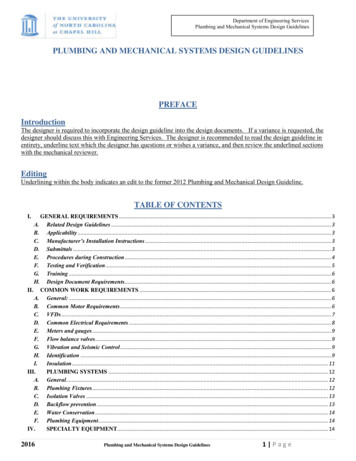
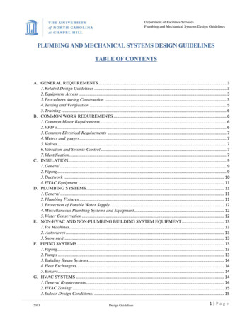
Department of Facilities ServicesPlumbing and Mechanical Systems Design GuidelinesPLUMBING AND MECHANICAL SYSTEMS DESIGN GUIDELINESTABLE OF CONTENTSA. GENERAL REQUIREMENTS .31. Related Design Guidelines .32. Equipment Access .33. Procedures during Construction .34. Testing and Verification .55. Training .6B. COMMON WORK REQUIREMENTS .61. Common Motor Requirements .62. VFD’s.63. Common Electrical Requirements .74. Meters and gauges .75. Valves.76. Vibration and Seismic Control .77. Identification.7C. INSULATION.91. General .92. Piping.93. Ductwork . 104. HVAC Equipment . 11D. PLUMBING SYSTEMS . 111. General . 112. Plumbing Fixtures . 113. Protection of Potable Water Supply . 124. Miscellaneous Plumbing Systems and Equipment . 125. Water Conservation . 12E. NON-HVAC AND NON-PLUMBING BUILDING SYSTEM EQUIPMENT . 131. Ice Machines . 132. Autoclaves . 133. Snow melt. 13F. PIPING SYSTEMS . 131. Piping. 132. Pumps . 133. Building Steam Systems . 144. Heat Exchangers. 145. Boilers. 14G. HVAC SYSTEMS . 141. General Requirements . 142. HVAC Zoning: . 153. Indoor Design Conditions: . 152013Design Guidelines1 Page
Department of Facilities ServicesPlumbing and Mechanical Systems Design GuidelinesH.I.J.K.20134. Heat Transfer Coils . 155. Cooling Condensate Drain Pans . 166. Cooling Condensate Traps . 167. Fan Coil Units . 168. Server room AHU’s . 169. Humidifiers . 17HVAC AIR DISTRIBUTION. 171. General Requirements . 172. HVAC Ducts . 173. Duct Accessories. 184. Fans . 185. Air Terminals / Air Valves . 186. HVAC Filtration . 18MODULAR AND BUILT-UP AHU’S . 191. Panels and doors . 192. Maintenance Requirements . 203. Gauges . 204. Leakage and deflection requirements . 205. UV Lights . 206. Dampers. 207. Flexible Connections . 218. Field Service and Equipment Startup . 21BUILDING LEVEL TEMPERATURE CONTROL SYSTEM. 21REFRIGERATION SYSTEMS . 21Design Guidelines2 Page
Department of Facilities ServicesPlumbing and Mechanical Systems Design GuidelinesA. GENERAL REQUIREMENTS1.Related Design Guidelines 2.EHS Laboratory Buildings Design Guidelines.Building Systems: Control System Guidelines.Building Systems: BSL3 Laboratory Design Guidelines.Energy Modeling GuidelinesSustainability Design GuidelinesSite Utilities Design Guidelines.Equipment Access 3.Clearances around equipment including air terminals, reheat coils, and air valves shall be sufficient toallow inspection, service, repair or replacement without removing elements of permanent construction.All trades must coordinate and protect the service area around equipment. It is emphasized thatequipment above ceilings must be replaceable without removing conduit, piping, cable trays, or otherpermanent constructions.All serviceable equipment (smoke dampers, fire dampers, control dampers, duct smoke detectors, fans,valves, coils, terminal units, pumps, filters, isolation valves, clean-outs, junctions, etc.) installed behindan inaccessible finished surface requires the installation of suitable access doors. Ensure that access isnot blocked by conduit, wire trays, ductwork, etc.It is the designer’s responsibility to identify, in the contract documents, the minimum size of all accessdoors.Designers are to indicate, on the plans, minimum clear maintenance access for all pieces of majorequipment including air handlers, terminal units, heat exchangers, boilers, chillers, air compressors,pumps, motors, fans, control valves (greater than 3”), etc. This should be indicated with a light, dashedline. The designer should generally provide the manufacturer’s recommended clearances. Specificrequirements which follow may exceed manufacturer’s recommendations:Air Handlers: 36 inches minimum access for fan compartments with motors 10 hp and larger. Alsoprovide coil pull access for the depth of the coil plus 18 inches and the width of the coil plus 30 inches onboth sides.Provide a means and a pathway for replacing the entire air handler without major demolition includingremoving permanent elements of construction.Boilers: Provide 24 inches on all sides except the burner, which should have 36 inches minimum.Control valves: For valves 3 inches and larger, provide access above the valve of the assembly heightplus 12 inches. Install ALL control valves in the vertical position, unless otherwise required by themanufacturer.Heat Exchangers: Provide tube pull plus 12” for shell and tube type exchangers.The designer should also be diligent with oversight of coordination in the field to prevent reduction toaccess due to conduit, piping, cable trays, etc.For demolition of existing HVAC, specify that all cut pneumatic tubes to be sealed w/ pneumaticplugs. Crimping and taping are prohibited.Procedures during Constructiona.General b.2013Specify all new and reused equipment installed under this scope of work to be completelycleaned to new condition (inside and outside). Specify required maintenance on reusedequipment to ensure it is ‘like new’.Specify that cleaning solutions may not be discharged to the storm sewer system.Spare parts are to be turned over to the owner and not left in the building mechanical rooms.Requirements for operating HVAC equipment during constructionDesign Guidelines3 Page
Department of Facilities ServicesPlumbing and Mechanical Systems Design Guidelines c.Flushing the domestic water system. d.2013Building must be fully enclosed, including installation of all doors, windows, etc.Set air handler to use 100% OA if construction is still generating dust and when conditions willnot allow the coil to freeze.If return air is to be used then all exhaust and return ducts/grilles shall be covered with temporaryfilter media (at a minimum a double layered cheesecloth and all filters media - MERV 8 required by LEED or other standards) to prevent dust infiltration into ductwork system.All chilled water piping shall be insulated.Laser alignment of pump shafts shall be completed and reports provided to the designer and alsoincluded in the O&M manuals.Supply and outside air connections of ductwork to AHU’s shall be complete.All manual dampers, fire dampers and combination fire/smoke dampers shall be open.All main supply ductwork shall be insulated.All safety circuits and basic control functions shall be
Plumbing and Mechanical Systems Design Guidelines 2013 Design Guidelines Building must be fully enclosed, including installation of all doors, windows, etc.
