Transcription
Part I1Plumbing Systems1Lecture NotesBy Dr. Ali HammoudB.A.U-20051
12Mechanical Engineering short-courseThis course is prepared for 3 rd mechanical and civilengineering students , at Beirut Arab University.This course concentrates on the design & calculations ofPlumbing systems, used in building applications.Course duration is 14 hours7 hours for cold & hot water distribution systems in building.7 hours for sanitary systems in building.By Dr. Ali HammoudAssociate professor in fluid mechanics& hydraulic machines2
13OBJECTIVESBefore an engineer sets out to design the plumbing services ofany project, it is necessary that he has well defined aims andobjectives in order to install an efficient and economicalplumbing systems.These can be defined as follows:1- Supply of Watera- Provide Safe Drinking-Water Supplyb- Provide an Adequate Supply of Water2- Fixtures unitsa- Minimum Number of Fixturesb- Quality Sanitary Fixturesc- Water Trap Sealsd- Fixture spacing3
14DRAINAGE AND SEWERAGESYSTEMa- Safe Drainage SystemAll sanitary drainage systems should be connected to thepublic sewer system (wherever available) at the nearestpossible point. In case the public sewer system is not available,a safe and non polluting drainage system must be ensured. Thedrainage system should be so designed as to guard againstfouling, deposit of solids and clogging.b- Vent PipesThe drainage system should be designed to allow for adequatecirculation of air within the system, thereby preventing thedanger of siphonage or unsealing of trap seals under normalworking conditions. The system should have access toatmospheric pressure and venting of foul gases by vent pipes.c- Exclusion of Foreign Substances from the Systemd- Ground and Surface Water Protectione- Prevention of Contaminationf- Prevention of Sewage Flooding4
Table of Contents part 1Symbol & legendDescription of Architecturedrawings of the project Design of Risers Daily W. Requirement Load Values W.F.U.Cold water distribution system“Calculation”Calculation”Hot water distribution system“Calculation”Calculation”Dr. HammoudDrawing of water distributioninside the flatsQuestions1 Pipe sizing Types of pumps Circulating Pump Pipe sizing Electrical W. heater Water storage heater Instantaneous orsemi-inst. heaters55
Symbols & legendsSSSOIL STACKWSWASTE STACKVSVENT STACKVVENTSVSTACK VENTRWRAIN WATERRWSRAIN WATER STACKCWCOLD WATERSWSOFT COLD WATERPWPOTABLE WATERHWDOMESTIC HOT WATERHWRTSWTRDOMESTIC HOT WATER RETURNTANK SUPPLYWATERDRDRAINAGEF.FFIRE FIGHTINGGGASACOMPRESSED AIRVVACUUMFOS1FUEL OIL SUPPLY66
CICAST IRON PIPEGSGALVANIZED STEEL PIPE ( SEAMLESS & WELDED )BSBLACK STEEL PIPE ( SEAMLESS )PVCPOLYVINYLCHLORIDE PIPEC-PVCCHLORINATED POLYVINYLCHLORIDE PIPEPVC-UUNPLASTICIZED POLYVINYLCHLORIDE PIPEP.PPOLYPROPYLENE PIPE ( DRAINAGE )P.P.RPOLYPROPYLENE RANDOM PIPE ( WATER )PE-XCROSS-LINKED POLYETHYLENE PIPEPE-X / AL / PE-XPE-X , ALUMINUM , PE-X ( TRIPLE LAYER ) PIPECUCOPPER PIPEP.EPOLYETHYLENE PIPEH.D.P.EAWCEWCBLAVSSHHIGH DENSITY POLYETHYLENE PIPEASIATIC WATER CLOSETEUROPEAN WATER CLOSETBIDETLAVATORYSINKSHOWERKSKITCHEN SINKBTBATHTUBDFDRINKING FOUNTAINHBHOSE BIBFTFLASH TANKFVFLASH VALVE177
COCCOFCOCLEANOUTCOCEILING CLEANOUTFLOOR CLEANOUTJ.BJUNCTION BOXRVCROOF VENT CAPMHMANHOLEFHCFIRE HOSE CABINETWSWATER SOFTNERWHWATER HEATERCLEANOUTCCOCEILING CLEANOUTFCOFLOOR CLEANOUTJ.BJUNCTION BOXRVCROOF VENT CAPMHMANHOLEFHCFIRE HOSE CABINETWSWATER SOFTNERWHWATER HEATERFAFROM ABOVEFAFROM ABOVETBTO BELOWTBTO BELOWIWIN WALLIWIN WALLUTUNDER TILEUTUNDER TILEUGUNDER GROUNDUGUNDER GROUNDUCLUNDER CEILING LEVELUCLUNDER CEILING LEVELI.F.SIN FLOOR SLABI.F.SIN FLOOR SLABBELOW FLOOR SLABB.F.SBELOW FLOOR SLABB.F.SLLLLLOW LEVELHLHIGH LEVELUPUPDNDOWNFMFROMNTSNOT TO SCALE1LOW LEVELHLHIGH LEVELUPUPDNDOWNFMFROMNTSNOT TO SCALE88
199
PLUMBING FIXTURES11010
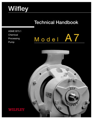
Project descriptionThe project consist of two blocks A and Band a common Ground floorfloor & 0ne BasementBlock A consist of 18 floors and block B consist of 17 floors.The design drawing of the two blocks are identical. Flat area isis about 700 m2.Each flat consist of one master bedroom, three bedrooms, one livingliving room, one dining room,one kitchen , maid room and six bathrooms.Floor to floor height is 3mWater supply from city main is irregular and we have to rely on two well pumps for waterdomestic use which have a capacity of 5m3/hr each. However drinking water is suppliedfrom city main water supply. The city water pressure is insufficient.insufficient.(a) Work out daily water requirement, underground and overhead tank capacity(b) Assuming indirect water supply system .Calculate the size of thethe the main riser pipefrom the underground reservoir up to overhead tank and the pump duty.(c) Assuming two downfeed risers from the overhead tank for each flatflat as indicated in thetypical floor drawing. .Calculate the pipe diameters and branchchlinesfor these risers.bran(d) Design the cold and hot water distribution system inside the flat.(e) size the pressure vessel of the top floors and the correspondingcorresponding pump duty.11111
Block A 18 floorsBlock B 17 floorsRefer to your drawing & follow the lecture1Typical floor 1212
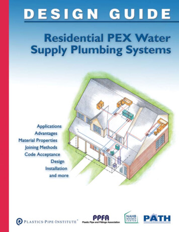
Heater 1Heater 2Riser 1B6B1B2B4Riser 2B5B3Riser 2 supply cold water toB1 B2 B3 B4Riser 1 supply cold water toB5 B6 Kitchen11313
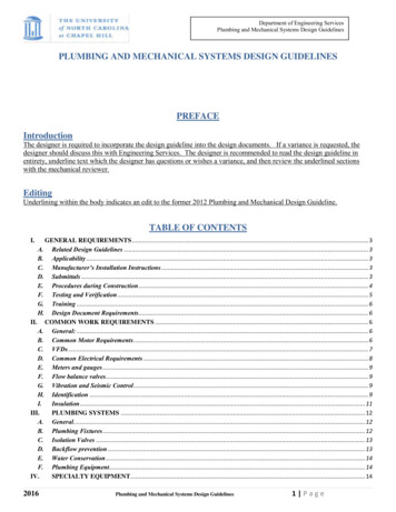
Cars1Ground floor1414
Waterstorage tanks1Basement floor 1515
HOW TO READ AND DRAW THEWATER DISTRIBUTION SYSTEMINSIDE THE FLAT .11616
Example of some pipeaccessories needed for waterdistribution system11717
EXAMPLE OF WATER DISTRIBUTION SYSTEM INSIDEBATHROOM – GALV. STEEL PIPES11818
11919
DETAIL OF WATER DISTRIBUTION SYSTEM INSIDEBATHROOM – P.P.R PIPES12020
DETAIL OF WATER DISTRIBUTION SYSTEM INSIDEBATHROOM – PEX OR PEX –AL-PEX PIPES12121
Solution of a ,b & cSchematic water risers diagram for Madam Cury project12222
Madam Cury project – water distribution systemE.W.for typical floorHeater1Solution of (d) Two Electrical waterheaters & two water risersElectricalW.Heater 212323
Madam Cury project – water distribution systemfor typical floorAnother versionSolution of (d)with single largeSingle Waterheater boiler12424
125Up to now !!Before starting the calculation of theplumbing project . Student should be ableto read and understand all theArchitecture drawings of the projectentitled “ Madam Curry “.25
Chap.2126Cold & Hot waterdistribution systems26
Calculation OfW.D. SystemsDesign Of W.D.SystemsDaily Water requirementLoad ValuesPressure requirementPipe sizing1 MaxZornada (2002)Pumpselection27Slide 2727
Water Distribution Systems Up to 10 floors BldgIndirectDirect12828
Distribution SystemsBuildings above 20 floorsPressure vesselPressure ReducerBreak- pressure ( Branch water supply )Break -Pressure reservoiresDirect supply ( Booster )or frequency inverterDirectIndirect12929
130Multi-pipes system is always preferableMuli-pipes systemUnderground TankEach flat has its own inlet flow pipe30
131Water storage in buildingsDomestic& PotableFire fightingIrrigation31
132Domestic water storage in buildingsUnderground tanksRoof tanks32
133Storage of waterWater is stored in buildings due to the irregular supplysupply of city water .Normally water is stored inbasement with pump transferring water to roof tanks .Roof tanks could one single tank for the whole building orseparate tanks for each flat.As shown in the following pages ,water tanks are providednormally with float valve, drain valve, discharge valve ,overflow and vent pipe.33
134Underground water storage Pumps –Tanks Connections34
135Roof TanksRoof tanks should be elevated enough above roof levelto have enough pressure for the upper apartment ,otherwise booster pump is needed.Material of roof tanks1-Concrete tanks.2-Galvanized tanks.3- PPr tanks.tanks35
136Concrete Roof tanks36
137Galvanized Roof tanksRef [4]37
138P.P.R. Roof tanks38
Riser diagram13939
1Riser diagram of thepresent project4040
Chap. 3141Design recommendations&Calculations41
142Fixture-Unit ComputationsComputing fixture units is a fundamental elementof sizing piping systems for water distributionand drainage. Values assigned to specific typesof fixtures are crucial in the sizing of aplumbing system. There are two types of ratingsfor fixture units:a) The first deals with drainage fixture units;b) and the second type has to do with the needsfor potable / domestic water systems. Bothtypes of ratings are needed when de signing aplumbing system.42
143Ref [8] providing you with sample tables of fixture-unitratings. The tables are based on actual code regulations, butalways refer to your local code for exact standards inyour region. As you look over the tables that will follow, payattention to all details. It is not unusual for coderequirements to have exceptions. When an exception ispres ent, the tables in code books are marked to indicate areference to the exclusion, exception, or alternative options.You must be aware of these notes if you wish to work withinthe code requirements. Computing fixture units is not acomplicated procedure and all you really need to know is howto read and understand the tables that will give you ratingsfor fixture units.Using fixture units to size plumbing systems is a standardprocedure for many engineers. The task is not particularlydifficult.43
Drainage Fixture Units144Pipes used to convey sanitary drainage are sized based ondrainage fixture units. It is necessary to know how manyfixture units are as signed to various types of plumbingfixture units. This information can be obtained, in most cases,from local code books. Not all plumbing codes assign the samefixture-unit ratings to fixtures, so make sure that you areworking with the assigned ratings for your region. Let me giveyou some sample tables to reviewWater Distribution Fixture unitsWater distribution pipes are also sized by using assignedfixture-unit ratings. These ratings are different fromdrainage fixture units, but the concept is similar. As withdrainage fixtures, water supply pipes can be sized by usingtables that establish approved fixture-unit ratings. Most localcodes provide tables of fixture-unit ratings.44
145Daily Water Requirement1-Daily water requirement & Tankscapacities. ( two methods are used todetermine the daily water requirement,the first is base on the number ofoccupants , the second is based on the loadvalue).2- Load value (W.f.u.)45
146Average Daily Water Requirement for StorageTable WW-1Type of EstablishmentRef [2]Gallons(per day per person)Schools (toilets & lavatories only)15Schools (with above plus cafeteria)25Schools (with above plus cafeteria plusshowers)Day workers at schools and offices35Residences153535-50Hotels (with connecting baths)50Hotels (with private baths, 2 persons perroom)10046
1Daily Water Requirement for Storage( Based on the number of occupants)47Example calculation of daily domestic water requirementSuppose we have 24 floors & each floor consists of 4 flats,2 of them having 3 bedrooms2 of them having 2 bedrooms. 1 Mad each flat.As a rule of thumb we take 2 persons/bed room.Total number/floor 2 3 2 2 2 2 4 24 Persons/floor.Total number of occupants 24 24 5 (labors conciergesetc ) 581 Persons.From table W-1 the daily water requirement is between 35-50gal/ day (Residential Building),The daily water requirement for the whole building is: 50 581 29000 gallons /day 110 m3/day47
148Capacity of Underground & Roof Tanks:Based on Plumbing code , the daily water requirement is dividedbetween the roof & underground tanks as follows:1 day's water requirement on the roof &2 day’s on the ground floor ( standard ).As mentioned before the total amount of water needed for the 24floors building is 110 m3 ,this equivalent to 110 tones additionalweight on the roof. On the other hand 2 x 110 220 m3 must bestored in the basement floor, this may affect the number ofcars in the basement.As a general rules ( one day water storage on the roof &basement may be satisfactory ,if water flow from well pump isguarantied ).N.B. Potable ( drinking cooking) water tank capacity is calculatedcalculated based on1010-12 L / person / day48
1Water storage for fire fightingz49For buildings , it is reliable that, water for fire fightingis provided by gravity storage wherever possible. Usingelevation as the means for developing proper waterpressure in water mains risers & FHCs, not dependent onpumps that could fail or be shut down as a result of anelectrical outage. Storage can be provided through oneor more large storage reservoirs or by multiple smallerreservoirs throughout the community that are linkedtogether .A reasonable rule of thumb is that waterstorage for fire fighting should be sufficient to provideat least one hour .For example, in a typical residentialbuilding with an ordinary hazards, the storage for fireflow of 100 GPM for 30-60 min may be appropriate.49
150Hose reel installation should be designedso that no part of the flooris more than 6 m from the nozzle when the hose is fully extended.The water supply must be able to provide a discharge of not less than33 gpm through the nozzle and also designed to allow not less thanthree hose reels to be used simultaneously at the total flow of 100gpm for one hour duration.The minimum required water pressure at the nozzle is 2 bar where themaximum allowable pressure is 6.9 bar. Adequate system pressures isabout 4.5 bars .Booster pump is used for top roof flats.The rubber hose reel length is 32 m & could be 1” or ¾” diameter(British standard), or 1.1/2”(US standard), and the jet should havea horizontal distance of 8 m and a height of about 5 m.For commercial building:Riser main pipe diameter D 2.1/2”Branch pipe diameter 1.1/2”Rubber hose reel diameter 1” .50
15151
152Siamese connectionLocated next to fire escape52
153Water stora
This course concentrates on the design & calculations of Plumbing systems, used in building applications. Course duration is 14 hours 7 hoursfor cold & hot water distribution systems in building. 7 hoursfor sanitary systems in building. By Dr. Ali Hammoud Associate professor in fluid mechanics & hydraulic machines . 3 13 OBJECTIVES Before an engineer sets out to design the plumbing services of .