Transcription
A Closer Look at Vertical Antennas With Elevated Ground SystemsRudy Severns N6LFINTRODUCTIONAmong amateurs there's been a long running discussion regarding the effectiveness of a vertical withan elevated ground system compared to one using a large number of radials either buried or lying onthe ground surface. NEC modeling has indicated that an antenna with four elevated λ/4-radials wouldbe as efficient as one with 60 or more λ/4 ground based radials. Over the years there have been anumber of attempts to confirm or refute the NEC prediction experimentally with mixed results. Theseconflicting results prompted me to conduct a series of experiments directly comparing verticals withthe two types of ground systems. The results of my experiments were reported in a series of QEX[1-7]and QST[8] articles (.pdf files of these articles are posted at: www.antennasbyn6lf.com ). From theseexperiments I concluded that at least under ideal conditions four elevated λ/4 radials could beequivalent to a large number of radials on the ground.Confirmation of the NEC predictions was very satisfying but that work must not be taken uncritically!My articles on that work failed to emphasize how prone to asymmetric radial currents and degradedperformance the 4-radial elevated system is. You cannot just throw up any four radials and get theexpected results. I'm by no means the first to point out that the performance of a vertical with only afew radials is sensitive to even modest asymmetries in the radial fan[10,11, 12], the presence of nearbyconductors or even variations in the soil under the fan[9]. These can cause significant changes in theresonant frequency, the feedpoint impedance, the radiation pattern and radiation efficiency. Theseproblems have been pointed out before but as far as I can tell no detailed follow-up has beenpublished. Besides the practical problem of construction asymmetries, at many QTH's it's simply notpossible to build an ideal elevated system even if you wanted to. There may not be enough space orthere may be obstacles preventing the placement of radials in some areas or other limitations. I thinkit's very possible that some of the conflicting results from earlier experiments may well have been dueto pattern distortion and increased ground loss that the simple 4-wire elevated system is susceptibleto.As the sensitivity of the 4-radial system and it's consequences sunk into my consciousness I began tostrongly recommend that people use at least 10-12 or more radials in elevated systems. Although Ihave heard anecdotal accounts of significant improvements in antenna performance when the radialnumbers were increased to 12 or more, I have not seen any detailed justification for that. Whatfollows is my justification for my current advice.My original intention for this article was to illustrate the problems introduced by radial fan asymmetriesand discuss some possible remedies. But in the process I came to realize that before going into theeffects and cures for asymmetries it was necessary to first understand the behavior of ideal systems.Ideal systems can show us when and why they are sensitive and point the way towards possiblecures or at least ways minimize problems. The discussion of ideal antennas (over real groundhowever!) also illustrates a number of subtleties in the design and possibly useful variations that differsomewhat from current conventions.1
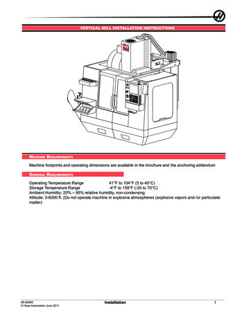
For these reasons, after some historical examples of elevated wire ground systems, I'll spend a lot oftime analyzing ideal systems and then move on to the original purpose of this article that wasasymmetric radial currents and how to avoid them. At the end of this article I summarize my advicefor verticals using elevated ground systems. While much of what follows is derived from NECmodeling, I have incorporated as much experimental data as I could find and compared it to the NECpredictions to see if NEC corresponds to reality.Prior work on elevated ground systemsLooking through my files I realized I had a lot of information on elevated ground systems: Moxon[11,12], Shanney[13], Laport[14], Doty, Frey and Mills[9], Weber[10], Burke and Miller[15, 16], Christman[18-33],Belrose[39, 42] and many others. I also found a good deal of my own work, some published but mostnot, so I decided to pull it all together and add some recent modeling work to shed light on thebehavior and the causes and possible cures of some of the problems associated with elevated radialsystems. Please note that there is an extensive list of references at the end this article.Some historyIn the early days of radio, operating wavelengths were in the hundreds or thousands of meters.Ground systems with λ/4 radials were rarely practical but very early it was recognized that anelevated system called a "counterpoise" or "capacitive ground", with dimensions significantly smallerthan λ/4, could be quite efficient. Figure 1 shows a typical example.Figure 1 - A typical counterpoise ground system. Figure from Laport[14].Here is an interesting quotation from Laport[14] regarding counterpoises:2
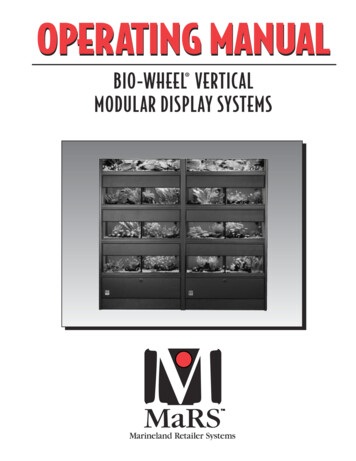
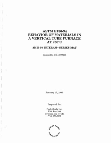
"From the earliest days of radio the merits of the counterpoise as a low-loss ground systemhave been recognized because of the way in that the current densities in the ground are moreor less uniformly distributed over the area of the counterpoise. It is inconvenient structurally touse very extensive counterpoise systems, and this is the principle reason that has limited theirapplication. The size of the counterpoise depends upon the frequency. It should havesufficient capacitance to have a relatively low reactance at the working frequency so as tominimize the counterpoise potentials with respect to ground. The potential existing on thecounterpoise may be a physical hazard that may also be objectionable."Laport was referring to counterpoises that were smaller than λ/4 in radius. In situations where λ/4elevated radials are not possible amateurs may be able to use a counterpoise instead. Unfortunately,beyond the brief remarks made here, I have to defer further discussion of counterpoises to asubsequent article even though I think they may be very useful to amateurs in some situations.Rectangular counterpoises, some with a coarse rectangular mesh, were also common. A rathergrand radial-wire counterpoise is shown in Figure 2.Figure 2 - A very large LF elevated ground system. From Admiralty Handbook of Wireless Telegraphy,1932 [34].Amateurs also used counterpoises. Figure 3 is a sketch of the antenna used for the initialtransatlantic tests by amateurs (1BCG) in 1921-22[35, 36]. The operating frequency for the tests wasabout 1.3 MHz (230m). At 1.3 MHz λ/4 189' so the 60' radius of the counterpoise corresponds to 0.08λ.3
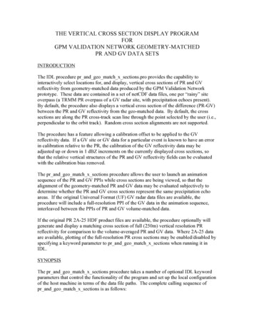
Figure 3 - EZNEC model of the 1BCG antenna.Note that in all these examples a large number of radials are used. The use of only a few radials,initially with VHF antennas elevated well above ground, seems to have started with the work ofPonte[37] and Brown[38].BEHAVIOR WITH IDEAL RADIAL FANSIn this section we'll look at verticals with a length (H) λo/4 (λo is the free space wavelength) andsymmetric elevated radial systems where the height above ground (J) and the number (N) and length(L) of the radials is varied. We'll also look at the effect of soils with different characteristics from poorto very good. Even though we will be looking at verticals with H λo/4, keep in mind that elevatedground systems can also be used with verticals of other lengths, with or without loading, inverted L's,etc. There can also be multi-band operation.NEC modelingFigure 4 shows a typical model of a vertical with a radial system. Except as noted, the followingdiscussion will focus on operation on 3.5-3.8 or 7.0-7.3 MHz as the operating band and 3.65 or 7.2MHz as a spot frequency near mid-band.The conductors (both the vertical and the radials) arelossless #12 wire. Most of the modeling was done over real grounds. The modeling used EZNECPro4 v.5.0.45, using the NEC4D engine. The use of NEC4D over real soils gives the correctinteraction between ground and the antenna. Excellent free programs based on NEC2 areavailable[41] but these do not properly model the ground-antenna interaction so that results obtainedfrom them must be used with some caution. For HF verticals close to ground this is an importantlimitation.4
Figure 4 - λ/4 ground-plane vertical with four radials.The effect of element dimensions on performanceThe simplest idea of a ground-plane antenna is that you take a quarter-wave vertical and add fourquarter-wave radials at the base. It is well known that the elements of a dipole will be a few percentshorter than λo so it is usually assumed that in a ground-plane antenna the vertical and the radiallengths will also be a few percent less than λo. Typically it is assumed that the vertical and the radialswill be individually resonant at the operating frequency. Unfortunately it's not that simple because thevertical is coupled to the radials and both interact strongly with ground because, at least at lower HF( 20m), the base of the vertical and radial fan will usually be only a fraction of λo above ground. Whatyou have in reality is a coupled multi-tuned system with complicated interactions. It turns out thatthere are a wide range of pairs of values for H and L that result in resonance or Xin 0 at thefeedpoint (where Zin Rin j Xin). Some of these combinations where neither the vertical nor theradials are individually resonant may be useful.Antenna resonance and element dimensionsThe free space wavelength (λo) at a given frequency in MHz (fMHz) is:𝜆𝑜 299.792983.570[𝑚 ] 5
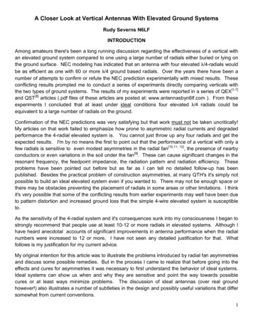
At 3.65 MHz, λo/4 67.368'. If we model a resonant λ/4 vertical over perfect ground using #12 wirewe find that at 3.65 MHz λ/4 H 65.663' that is about 3.5% shorter than λo/4.To take into account the effect of ground on radial resonance for a given value of J and soilcharacteristic, it has been suggested that we can erect a low dipole at the desired radial height (J)and trim its length to resonance. An example of this is given in Figure 5.Figure 5 - Dipole half-length for resonance for different values of J and different soils.For J 8', depending on the soil, L varies from 64.5' to 66.4'. As we reduce J we find that L getssmaller. The shift in resonance for radials close to ground has also been demonstratedexperimentally[2]. Figure 6 shows the measured radial current at 7.2 MHz on 33' radials (sum of fourradials). Clearly this radial is λ/4 resonant at a lower frequency than 7.2 MHz! As Figure 5 predictsthe effect gets much larger for small values of J.6
Figure 6 - Measured current on a 33' radial at 7.2 MHz. Four radials lying on the ground surface.What do we mean by "resonant' values for H and L independently? It's not just that the reactancescancel at the feedpoint. When I say "the resonant length for H or L" I'm talking about the case wherethe current distribution on the vertical and the radials independently corresponds to resonance: i.e.the current just reaches a maximum at either the base of the vertical or at the inner ends of theradials. If either H or L is made longer than resonance, the current maximum will move out onto theradials or up the vertical. Figure 7 shows the current distribution on a vertical and the radials for threecombinations of H and L each of which yield Xin 0 at the feedpoint.Figure 7 - Current distribution on the vertical and the radials. The current starts at the top of thevertical, runs to the base and then out along the radials. The radial current is the sum of the currentsin the four radials. The currents are for 1 Arms at the feedpoint.7
To better understand what's happening we can expand Figure 7 around the 1 A feedpoint (indicatedby the arrow) as shown in Figure 8.Figure 8 - Current distribution on the vertical and the radials expanded around the feedpoint. Thearrows point to the junctions between the vertical and the radials.For H 64' and L 80.85', the current on the vertical has not peaked so the vertical is too short forresonance. However, the radial current peak is well out on the radials so clearly the radials are toolong for resonance. The reactance of the vertical and the radials cancels at the feedpoint so theantenna is "resonant" but not the vertical and radials individually. Similarly, for H 69' and L 58.8', thecurrent in the vertical peaks and begins to fall (moving from the top to the bottom of the vertical)before the feedpoint is reached. Again, we have a resonant antenna but the vertical and the radialsare not individually resonant. However, if we set H 67' and L 67.66', both the vertical and the radialsare λ/4 resonant individually.The "resonant" (by the definition given above) length of the vertical is 67' and the "resonant" length forthe radials is 67.7', both of these lengths are substantially different than the value we got earlier forλ/4 resonance for a vertical over an infinite perfect ground-plane (65.7'). The "resonant" radial lengthof 67.7' is quite different from the dipole 8' over average ground (64.7'). H and L are actually closestto λo (67.4'). What we have just seen is only one particular example. If we change J and/or the soilcharacteristics and/or the number of radials these lengths will change!8
Setting up the antenna so that both the vertical and the radials are individually resonant turns out tonot be so simple and we might ask, "is it really necessary to have both the vertical and the radialsresonant individually?" It turns out that there are other considerations besides the current distributionwith regard to the choice of L for a given H. It is possible to use values of L where Xin 0 andcompensate for that with a tuning impedance at the feedpoint for example or perhaps use some tophat loading. In addition, in some situations it may not be possible to have radials long enough tomake Xin 0 while keeping the radial fan symmetric. Further, it has bee
NEC modeling has indicated that an antenna with four elevated λ/4-radials would be as efficient as one with60 or more λ/4 ground based radials. Over the years there have been a number of attempts to confirm or refute the NEC predictionexperimentally with mixed results. These conflicting results prompted me to conduct a series of experiments directly comparing verticals wi th the two types of .