Transcription
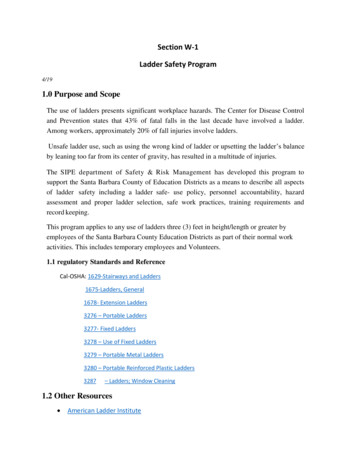
Body Control IGlideLoc Fall ArresterUniversal IIGlideLoc Fall ArresterGlideLoc Vertical Height Access Ladder System KitsUSER INSTRUCTION MANUALI284 Rev. CMFP9720153March 2017
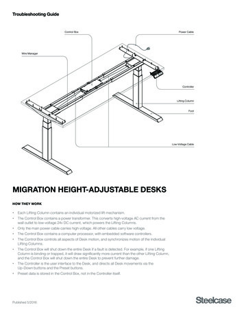
TABLE OF CONTENTSSOMMAIRE1GlideLoc System Kit DiagramSchéma de l’ensemble du système GlideLocInstructions for UseMode d’emploiEN English. 3-1312kN End StopsButées 12 kNFR Français. 14-25Appendix A: System ReplacementParts. 26Annexe A: Pièces de rechange du systèmeAppendix B: Inspection and MaintenanceLog. 27Guide Railw/Rail Connector2Rail de guidage avecconnecteur de railAnnexe B: Registre D’inspection et D’entretien3Appendix C: System TagParts. 27Annexe C: Étiquette du systèmeDownload this manual and product specification sheetsat: www.millerfallprotection.comTéléchargez ce manuel et les fiches techniques sur:www.millerfallprotection.comFall ArresterDispositif antichuteGlideLoc System Kit DiagraMSCHÉMA DE L’ENSEMBLE DU SYSTÈME GlideLOC41Rung ClampAttache de fixationde barreau2
ENINSTRUCTIONS FOR USEFall Protection SystemsVERTICAL LADDER CLIMBINGSYSTEM KITSThank you for your purchase of Honeywell Miller fall protectionequipment manufactured by Honeywell Industrial Safety.WARNINGAll persons using this equipment must read,understand and follow all instructions. Failure todo so may result in serious injury or death. Do notuse this equipment unless you are properly trained.It is crucial that the authorized person/user of this equipmentread and understand these instructions. In addition, federallaw requires employers to ensure that all users are trained inthe proper installation, use, inspection, and maintenance offall protection equipment. Fall protection training should bean integral part of a comprehensive safety program.Proper use of fall arrest systems can save lives and reducethe potential of serious injuries from a fall. The user mustbe aware that forces experienced during the arrest of a fallor prolonged suspension may cause bodily injury. Consulta physician if there is any question about the user’s abilityto use this product. Pregnant women and minor childrenmust not use this product.1.0 PurposeThe innovative GlideLoc Vertical Height Access LadderSystem Kit is designed to be permanently installedto existing vertical fixed ladders to provide superiorworker maneuverability and fall protection in ladderclimbing applications. It is ideal for wind power/turbines,telecommunications, utilities, industrial facilities, drilling rigs/platforms, shipbuilding, crane installation and confined space.The GlideLoc System meets local standards requirements.2.0 General Requirements,Warnings and Limitations2.1 General Fall Protection WarningsAll warnings and instructions shall be provided to authorizedpersons/users. Warnings and instructions must be readand understood prior to using this equipment.All authorized persons/users must reference theregulations governing occupational safety, as well asapplicable standards (i.e, ANSI or CSA).Proper precautions should always be taken to remove anyobstructions, debris, material, or other recognized hazardsfrom the work area that could cause injuries or interfere withthe operation of the system.All equipment must be inspected before each use accordingto the manufacturer’s instructions.All equipment should be inspected by a qualified person ona regular basis.To minimize the potential for accidental disengagement, acompetent person must ensure system compatibility.Equipment must not be altered in any way. Repairs must beperformed only by the equipment manufacturer, or personsor entities authorized, in writing, by the manufacturer.Any product exhibiting deformities, unusual wear, ordeterioration must be immediately discarded.Do not use if the unit or any part of the system appears tobe damaged.Any equipment subject to a fall must be removed fromservice. (Refer to 9.0 Inspection and Maintenance.)The user shall have a rescue plan and the means at hand toimplement it when using this equipment.Never use fall protection equipment for purposes other thanthose for which it was designed. Fall protection equipmentshould never be used for towing or hoisting.Never remove product labels, which include importantwarnings and information for the authorized person/user.2.2 System Warnings and LimitationsSystem CompatibilityGlideLoc Kits are designed for use with Honeywell-approvedcomponents only. Substitution or replacement with nonapproved component combinations, sub-systems, or both,may affect or interfere with the safe function of each other andendanger the compatibility within the system. This incompatibilitymay affect the reliability and safety of the total system.GlideLoc Kits must be used in conjunction with the BodyControl I GlideLoc Fall Arrester with auto-locking carabiner,Comfort GlideLoc Fall Arrester with auto-locking carabiner,Comfort2 GlideLoc Fall Arrester with auto-locking carabiner,or the Universal II GlideLoc Fall Arrester with auto-lockingcarabiner and a Miller full-body harness equipped with afront attachment point designated for ladder climbing.[NOTE: All instructions and warnings provided with thefall arrester and harness must be read and understoodbefore using the equipment.]System CapacityThe GlideLoc System can sustain multiple users so longas the load-bearing capacities of the base structure, ladderand ladder attachment are adequate. One (1) person perguide rail section is permitted. The distance betweenusers must not be less than 7 ft. (2.1m) to ensure that, inthe event of a fall, the person falling will not strike a userbelow. The maximum number of workers allowed by ANSIA14.3 is four (4) per system.Fall ClearanceEnsure that adequate clearance exists in the fall path to avoidstriking a lower level, some other object, or another user.Fall Arrester CapacityFall arresters are designed for use by one person only.Maximum capacity is 310 lb. (140.6kg). DO NOT EXCEEDTHIS WEIGHT.3
Environmental HazardsUse of this equipment in areas where environmentalhazards exist may require additional precautions to limit thepossibility of injury to the user or damage to the equipment.Hazards may include, but are not limited to, extremetemperatures, caustic chemicals, corrosive environments,high voltage power lines, explosive or toxic gases, movingmachinery, and sharp edges. Do not expose the equipmentto any hazard which it is not designed to withstand. Consultthe manufacturer in cases of doubt. Guide rail must be kept clean--free of dirt, residual mortar,and other substances. Use of this system is not suitable when the user ispositioned on an unstable surface, fine-grain material,or particulate.or entities authorized, in writing, by themanufacturer.3.0 System RequirementsBefore installation of a GlideLoc Kit, the structure andladder on which the system is to be affixed must be certifiedto be capable of withstanding the potential loads that maybe applied in the event of a fall arrest and must meet thespecified ladder requirements.Ladder RequirementsFor the kits, a ladder must be a fixed ladder with rungshaving outer diameters between 3/4 inch (19.1mm) and1-1/4 inches (31.8mm). For ladder rungs with largerdiameters, rung clamps with longer hardware are availablewhich will accommodate rungs up to 1-3/4 inches (44.5mm).According to ANSI A14.3, the minimum width of the laddermust be 16 inches (406.4mm) from inside rail to inside rail.For non-standard ladder rungs, please contact MillerTechnical Services at 800-873-5242 for additionalinformation and installation assistance.The integrated shock absorber of the Body Control I,Comfort, Comfort2 and Universal II fall arresters limits fallarrest forces to 1350 lbf. (6kN). This is the maximum forceon a ladder system for a single user.To calculate the maximum working load rating on a laddersystem with more than one user, the following formula canbe used as a guide:Ladder Working Load Rating (Fall Arrest Force (Maximum# of Users – 1 x Weight of Worker))Example: Ladder rated for 4 users at 250 lbf. each:Ladder Working Load Rating (1350 lbf. (3 x 250 lbf.)) 2100 lbf. Ladder Working LoadTo calculate the maximum working load rating on an individual ladder rung for more than one user, the followingformula can be used as a guide:Ladder Rung Working Load Rating (Fall Arrest Force (Maximum # of Users – 1 x Weight of Worker))# of Ladder ClampsExample: Ladder rated for 4 users at 250 lbf. each on aGS0040 system:Ladder Rung Working Load Rating (1350 lbf. (3 x 250 lbf.))74 300 lbf. per Ladder RungImportant Notes:1. Working load rating DOES NOT INCLUDE A SAFETYFACTOR.2. Specific ladder compliance standards may varyand must be used when required to determinerung force requirements and safety factors.3. The fall arrester limits the maximum fall arrestforce to under 1350 lbf. (6kN). This is the maximumforce on a ladder system for a single user.4.0 Description of System Components4.1 GlideLoc System Kit1) 12kN End Stops For use at top and bottom of rail system. Prevents incorrect insertion of the fall arrester andunintended disengagement of the fall arrester from the rail.2) Guide Rail w/Rail Connector Installs easily to vertical fixed ladders with varyingrung diameters and spacing. Markings identify the upper end of the rail to preventincorrect installation. Rail connector connects two guide rails sections. Rail available in 10 ft.-1 in. (3.08m) increments ingalvanized steel, stainless steel and aluminum.3) Body Control I, Comfort or Comfort2Fall Arrester Fall arrester purchased separately. Durable stainless steel & aluminum construction (BodyControl I/Comfort) or complete stainless steel constructionfor maximum corrosion-resistance (Comfort2). Quick and easy to install with single-hand operation. The safety pin protruding from the side of the fallarrester, together with the end stop, prevents the fallarrester from being inserted incorrectly in the rail. Allows smooth, hands-free climbing with or withoutleaning back. Locks quickly in the event of a fall. Integrated shock absorber/fall indicator limits fallarrest forces to 1350 lbf. (6kN) and provides for easeof inspection.ORUniversal II Fall Arrester Fall arrester purchased separately. Complete stainless steel construction for maximumcorrosion-resistance. May be inserted or removed at any point along theguide rail. Quick and easy to install with single-hand operation. Failsafe design ensures correct usage. Allows smooth, hands-free climbing. Locks quickly in the event of a fall. Integrated shock absorber/fall indicator limits fallarrest forces to 1350 lbf. (6kN) and provides forease of inspection.4) Rung Clamp Secures guide rail to ladder rungs. Available in galvanized steel, stainless steel & aluminum.4.2 System Replacement PartsSee Appendix A.
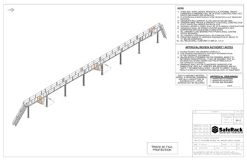
Ensure that the structure/ladder on which the GlideLocKit is to be affixed is capable of withstanding loads resulting from a fall (see 3.0 System Requirements). Guide rail sections must be clean--free of dirt, residualmortar, and other substances--before installing. When installing components throughout the system, boltsmust be inserted from the front of the system to the backto ensure proper operation of the fall arrester on the rail. Use only Miller approved components and fasteners inthis system. Do not use substitute parts.WARNINGSecondary personal fall protection is requiredduring installation. Persons installing thesystem must use caution and shall not beexposed to a fall hazard during the installationprocedure. Do not connect to any partiallyinstalled component within the system.System Installation Overview: The GlideLoc System maybe installed from the bottom of the ladder up or from thetop down. Consideration should be given to the lengthof the system, the ladder application, the availability ofscaffolding, the top rail requirements, etc.Top Rail Requirements -- The top rail section of the systemmust be a complete 10 ft.-1 in. (3.08m) section. The toprail section cannot extend above the top ladder rung bymore than 36 in. (914mm). It is recommended that thebottom rail section be modified or cut to meet theserequirements. Therefore, if it is not possible to measureor calculate whether the top rail section will meet theserequirements due to the length of the ladder and system, itmay be necessary to install the system from the top of theladder down to ensure compliance.1. Place the back of the guide rail section flat against therungs of the ladder at the desired height and hold inplace.2. Install the rung clamp by placing the clamp jaws overa ladder rung and aligning the holes on the rung clampwith the oblong holes in the guide rail. Insert first boltthrough the aligned holes above the ladder rung andattach a washer and nut; then attach a second nut,using it to jam the first nut in place (see Fig. 1c - Note:For stainless steel and aluminum rung clamps, a washerand one self-locking nut are used). Insert second boltthrough the aligned holes below the ladder rung andagain attach a washer and two nuts. Torque fastenersto 18.5 ft.-lbs. (25Nm).Follow above procedure to install additional rung clampsensuring that clamps are spaced according to specifications.Fig. 1aFig. 1bRung ClampArrow StampingRed PlasticRibbonRung ClampFig. 1cRung ClampMax. 7 ft. (2.1m) Before installation, carefully inspect all components ofthe system according to the manufacturer’s instructions(see 9.0 Inspection and Maintenance). Do not use ifthere are any damaged or missing parts (see 4.2 SystemReplacement Parts).NOTE: Rung clamps must be spaced a maximum of7 ft. (2.1m) apart (from center to center - see Fig. 1b)throughout the system. Never install a system withfewer than four (4) rung clamps.Max. 7 ft. (2.1m)5.0 System InstallationTools Required for Installation
having outer diameters between 3/4 inch (19.1mm) and 1-1/4 inches (31.8mm). For ladder rungs with larger diameters, rung clamps with longer hardware are available which will accommodate rungs up to 1-3/4 inches (44.5mm). According to ANSI A14.3, the minimum width of the ladder must be 16 inches (406.4mm) from inside rail to inside rail.