Transcription
Operations Manual
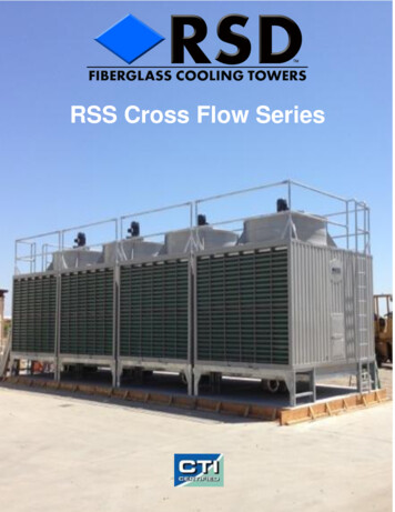
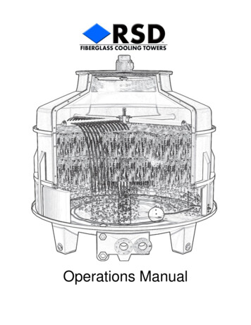
RSD Cooling Tower Operation Manual1. General2. Description2.1 Tower Shell2.2 Motor2.3 Fan2.4 Sprinkler Assembly2.5 Fill2.6 Casing2.7 Water Basin2.8 Air Inlet Louvers2.9 Support System2.10 Ladder3. Installation Guidelines3.1 Location3.2 Mounting Base3.3 Fluid Connections3.4 Electrical Connections3.5 Freeze Protections3.6 Water Treatment4. Start up Procedures4.1 Cleaning4.2 Trial Water Circulation4.3 Inspection Check List5. Maintenance5.1 Motor & Gear Reducer5.2 Sprinkler Assembly5.3 Strainer5.4 Fill5.5 Water Basin5.6 Casing5.7 Paint5.8 Water Make up6. Electrical6.1 Wiring Information and TableTower cut-away 11111213/141516Web: rsdcoolingtowers.com- Email: towers@rsd.net - Phone: 800-245-8007 - Fax: 949-461-7459rev 06 - 122
1. GeneralThe following information is intended to assist you in obtaining efficient, long-term performance from your RSD COOLING TOWER. Tower construction & function as wellas field adjustment and inspection procedures are described below.2. DESCRIPTION2.1 Tower ShellThe tower shell is a cylindrical, bottle shaped design whichminimizes internal pressure drop. This design virtually eliminates ineffective space in the cooling layers, thus providing excellent cooling efficiency and space economy.2.2 MotorsAll tower motors are U.L. RECOGNIZED for outdoor duty. ModelsRSD003 through RSD175 utilize direct drive motors ranging from 6pole(1150 rpm) through 10 pole(600rpm). Models RSD200 throughRSD1000 utilize 4 pole motors with gear reducers. Due to superiortower design, motor hp and consequently energy consumption issignificantly less than on traditional towers.2.3 FansOur axial flow fans have been specifically designed for toweruse. They provide a large volume of stable air at lowpressure while maintaining desired low noise levels.2.4 Sprinkler AssemblyThe sprinkler assembly is constructed of 100% non corrosive material. Mounted onthe top of a center stand pipe, the sprinkler assembly distributes the water evenlythrough 4, 6 or 8 distribution tubes. A minimal head pressure is required to ensureproper adjusting rotation. The specific RPM can be obtained by the distribution tubeangle. Refer to the table in paragraph 4.2 for RPM requirements.Web: rsdcoolingtowers.com- Email: towers@rsd.net - Phone: 800-245-8007 - Fax: 949-461-7459rev 06 - 123
2.5 FillOur standard tower fill is constructed of a heat embossedhoneycombed P.V.C film. This honeycomb constructionensures even water distribution and high efficiency waterto air heat transfer. The fill will withstand a maximum inletwater temperature of 130f, however, to ensure long lifeinlet temperatures over 115f.are not recommended. Thefill is guaranteed for two (2) years providing 115f.maximum inlet water and proper water treatment.2.6 CasingThe tower casing is constructed of Fiberglass ReinforcedPolyester. (FRP)This material is light weight, durable and non-corrosive. The resilient nature of (FRP) will provide anadditional margin of safety during high winds, earthquakes,etc.2.7 Water BasinThe water basin is constructed of 100% F.R.P. Ourtapered bowl design channels all outgoing water to arecessed sump which ensures a steady flow of water tothe pump; even when operating at low water levels,minimizing the chance of cavitations. This design alsoallows for easy access to the entire basin surface for easycleaning. All fluid connections are located on a commonbulkhead directly adjacent to the sump. RSD400 andlarger towers have the addition of an auxiliary suction tankto simplify connections.2.8 Air Inlet LouversAll towers RSD40 and above are equipped with ourpremium air inlet louvers. These louvers virtuallyeliminate splash from the tower basin. They alsoprevent airborne debris from entering thetower. Premium louvers are available as optionalequipment on smaller RSD003 thru RSD030.Web: rsdcoolingtowers.com- Email: towers@rsd.net - Phone: 800-245-8007 - Fax: 949-461-7459rev 06 - 124
2.9 Support SystemsRSD3 through RSD350 towers employ F.R.P. support legs that are an integral part ofthe basin construction. On RSD400 and larger towers, the support structure isconstructed of hot dipped galvanized steel. Motor support assemblies and fill supportcomponents are also constructed of cast aluminum or hot dipped galvanizedmaterial. R.S.D. utilizes exclusively stainless steel fasteners to ensure long life andeasy disassembly during maintenance and repair operations.2.10 LaddersAll towers RSD100 and larger are equipped with anOSHA standard ladder for safety and convenience.3. INSTALLATION GUIDELINESIn order to ensure that you receive the best possible performance from your RSDCooling Tower, it is important that you follow some basic guidelines.3.1 Location1. RSD towers are designed for outdoor installation. If indoor installation is desired,contact our technical support department to determine if our product is suitable foryour application.2. In all cases your tower should be located to ensure sufficient airflow. Refer to thetower nameplate or RSD catalog to determine the required CFM for your particularmodel.3. If the tower will be located in a parapet or behind an enclosure refer to the followingguideline; For a ventilated enclosure; ensure that the louvers are sized to allow for the cfmrequirements of your tower.For a non-ventilated enclosure; there must be a distance equal to ½ the towerdiameter on all sides of the tower.For a rectangular or odd shape enclosure; it is acceptable to locate the toweradjacent to the enclosure wall providing there is a minimum distance equal to atleast 1 tower diameter on one side.To Avoid Short Cycling; the unit must be mounted to ensure that the top of thewall is no more than ½ the fan diameter or 36” (which ever is less.) above the towerstack. It is also not recommended that the tower be installed directly under or nearan overhang.Service Access; should always be considered we installing a cooling tower. Selecta location that would allow for easy maintenance and service access. This isparticularly important on gear drive towers that may require crane access for motorassembly repairsWeb: rsdcoolingtowers.com- Email: towers@rsd.net - Phone: 800-245-8007 - Fax: 949-461-7459rev 06 - 125
3.2 Mounting BaseIt is very important that the tower mounting base beas level as possible. If the tower leans too severely,there is a possibility for poor sprinkler rotation and/orfailure.Towers that are installed on any raised platformmust be firmly secured. There is a mounting hole inthe center of each basin leg for this purpose. The factory can provide you with thebasic mounting dimensions to aid in platform construction.Note: Prior to any roof top or elevated installation be certain that the support structuremeets all applicable building codes as they pertain to the tower operating weight. Alsovibration or seismic isolation be used as required. RSD can provides OSPODapproved Isolation kits for all models.On towers RSD100 and larger, field assembly is sometimes required. If possible, thetower should be assembled on the actual support structure. If it becomes necessary tolift the tower, consult the factory for specific load point and lifting requirement. RSDcan provide specifications and drawings for support frames if desired.3.3 Fluid ConnectionsAll fluid piping must be in accordance with local plumbing and mechanical codes. Ontowers with iron pipe supply and return water lines AVOID HANGING THE WEIGHTOF THE PIPING ON THE TOWER FLANGES. It isrecommended that the piping be supported no more than18" from the actual tower connections. Failure to do thiscould cause damage to the tower bulkhead and void thewarranty.It is also recommended that a vibration joint be installed toprotect these fittings from possible line vibration .3.4 Electrical ConnectionsModels RSD003 through RSD008 are available 115/230 1ph only. RSD010 throughRSD020 are available 115/230 1ph or 230/460 3ph. Models RSD025 and larger areavailable in 230/460 3ph only. On all towers with gear reducer fan drivers, the motorshould be wired for soft (low torque) start. This can be accomplished by either using awye-delta starter, a solid state soft start controller, or a (VFD) variable frequencydrive. Failure to do this may cause premature gear reducer failure. See Sec 6.0 forWiring detail3.5 Freeze ProtectionThe following precautions should be taken on any low ambient installation. (anytower that will routinely see temperatures below 30F.). Thermostaticallycontrolled sump heaters should be installed to protect against tower freeze upand possible basin damage. On towers that are not used during winter monthsthe tower basin and stand pipe should be drained.Web: rsdcoolingtowers.com- Email: towers@rsd.net - Phone: 800-245-8007 - Fax: 949-461-7459rev 06 - 126
3.6 Water TreatmentTo avoid poor performance and premature systemfailure, WATER TREATMENT IS ESSENTIAL.A. Scale:During typical tower operation water evaporates at the rate of 1.7 gph per ton. Properwater treatment prevents these minerals from forming scale on all of the surfaces inthe system. Failure to properly treat your tower will result in the formation of scale andcan significantly reduce the efficiency of your system and ultimately cause failureB. Bacteria:Under certain environmental conditions high bacteria content in the water may causealgae to form in the tower. If this occurs tower performance will be impaired4. START UP PROCEDURES4.1 CleaningDuring assembly and/or transportation of the tower it is likely that dirt and othermaterials have accumulated. Remove any material from the basin that may not becarried out by normal water flow. Open the drain and wash the basinthoroughly. NOTE: It is safe to enter the tower and walk on the basin. On RSD80 andabove use care around seams and support leg cavity covers to avoid possible sealdamage.4.2 Trial Water CirculationReach in through either the top or the side inspection hole and rotate the sprinklerassembly clockwise to ensure that it spins freely. Fill the tower to operation level(approximately even with the lower lip of the tower basin). It may be necessary toadjust the float up or down to maintain the proper water level. Start and run thecirculating pump until all air is driven out of the piping. When the circulating waterbecomes steady, check to be sure the sprinkler is rotating smoothly and at the properclockwise RPM as specified below. See section 5.2 for adjustment procedure.Web: rsdcoolingtowers.com- Email: towers@rsd.net - Phone: 800-245-8007 - Fax: 949-461-7459rev 06 - 127
4.3 Inspection Check ListA. After the circulation test is complete, examine the tower strainer and thedistribution tubes, and remove any material that may have collected.B. Spin the fan by hand to be sure it rotates freely and has ample tip clearance.C. On RSD175 and larger check gear reducer oil level. Add oil if necessary.D. Double check and re-tighten all fan and motor assembly bolts. On RSD40 andabove be sure to check the fan blade u-bolts.E. Confirm that the fan motor supply voltage is correct. Run the fan momentarily toensure proper clockwise rotation.F. Run the fan for two to three hours and check for abnormal noise orvibration. Check the phase, current and voltage measurements to ensure that theyagree with motor nameplate data. (NOTE: on larger towers that employ gearreducers, noise levels at start up will be higher than normal due to gear break in. Seesection 6.1 for more information.G. Double check make-up water system and float valve adjustment.H. Install and secure tower fan guard and air inlet louvers.5. MAINTENANCE5.1 Motor & Gear Reducer (where applicable)A. After the first week of operation the original lubricating oil should be removed. Forbest results, the oil should be removed while at working temperature. To drain thegear reducer oil, simply open the hand valve located on the side of the assembly anddrain the contents into an appropriate container.B. Thoroughly flush the gear box with mineral flushing oil containing no additives.C. Refill the gear box to the top fill line on the reducer dip stick. To locate the dip stickremove the pipe cap located adjacent to the drain valve. The suggested lubricantsare listed below.Web: rsdcoolingtowers.com- Email: towers@rsd.net - Phone: 800-245-8007 - Fax: 949-461-7459rev 06 - 128
D. Check the oil level weekly and add oil as needed. Check for signs of moisturecondensation or oil sludge. If condensation or sludge is present, change the oilimmediately.E. Under normal conditions, the lubricating oil should be changed EVERY SIXMONTHS OR 3000 HOURS OF OPERATION. However there are conditions that maymake it necessary to change the oil at one or two month intervals. Unusually highambient temperatures with intermittent tower load can cause the gear reducertemperatures to rise and fall rapidly. This condition may cause higher than normalcondensation to occur which will contaminate the oil and cause sludge to form.F. Motor & gear reducer adjustment: After start-up orduring motor or gear replacement, it may be necessary toadjust the alignment of the motor and gear reducer. Theassembly basically consists of two mesh gears one motor(pinion) gear and one main (drive) gear. The onlyadjustment is on the horizontal plane. To obtain the bestfeel of the gear alignment, remove the fan housing fromthe top of the motor. By rocking the motor cooling fan in aclockwise/counter-clockwise direction you will feel theactual gear tolerance. You should experienceapproximately 1/8" of play in the assembly. Adjustment isachieved by loosening the (4) mounting bolts that securethe motor to the reducer. If the gear is too loose, simply tap the motor in, toward thecenter of the reducer. Check the play in the gears and continue the process until thedesired tolerance is achieved.5.2 Sprinkler AssemblyAlthough the sprinkler assembly is constructed of non corrosive materials, water scaleand entrained material can affect its operation.A visual inspection of the sprinkler distribution tubes should be conducted EVERY 30DAYS. check to ensure that the water is flowing smoothly out of all tube holes. OnRSD40 and larger towers the inner most holes are the smallest thus this is where anyrestriction should be first observed.Web: rsdcoolingtowers.com- Email: towers@rsd.net - Phone: 800-245-8007 - Fax: 949-461-7459rev 06 - 129
A. Cleaning: Distribution tubes can be cleaned or replaced as required. In doing so,first loosen the locking nut, and then unscrew the tube. On RSD40 and larger towersyou may remove the distribution end cap to clean the inner wall of thetube. NOTE: when cleaning out the distribution tube holes avoid enlarging the holesby drilling as this will affect the water distribution pattern and tower performance.B. Adjusting: To adjust distribution tubes; while facing the sprinkler head rotatethe tubes until the outlet holes are at approximately the 4 o'clock position. This willprovide you with a good starting point. Start the circulating pump and compare youractual R.P.M. to the chart in section 4.2. To increase R.P.M. rotate the tubes counterclockwise. To decrease R.P.M. rotate the tubes clockwise. Once the desired speed isobtained tighten down locking nuts.C. Removing Sprinkler Head: If uniform low water flow and/or slow rotation isobserved it may be necessary to remove and clean the sprinkler head assembly. Thiscan be accomplished by first removing all distribution tubes and then unscrewing thehead assembly from the tower stand pipe.5.3 StrainerThe cooling tower strainer is intended to prevent foreignmaterial from reaching the pump, heat exchanger and waterdistribution system. A periodic cleaning of the strainer willensure proper water flow and aid system operation.5.4 FillIn order to maintain optimum tower efficiency, EVERY 6MONTHS OR 3000 HOURS OF OPERATION, it isrecommended that the fill be examined for signs ofdeterioration and non-uniform water distribution. Undernormal conditions (95 to 115 degree f. return water) thefill should retain its effectiveness for manyyears. However, application conditions such assuspended solids, poor water treatment or higher thannormal return water temperatures (over 115 degree f.)may cause premature clogging and/or fill deterioration.Web: rsdcoolingtowers.com- Email: towers@rsd.net - Phone: 800-245-8007 - Fax: 949-461-7459rev 06 - 1210
A: Fill removal and replacement:RSD3 through 30:1. Remove the fan guard, motor frame and fan assembly.2. Remove the FRP upper casings.3. Remove the sprinkler assembly.4. You should now be able to remove fill sections as needed.RSD40 through 1000:1. Remove the fan guard, motor frame and fan assembly.2. Remove fan guard.3. Loosen and remove 1/2 of the motor frame mounting bolts.4. Remove 2 to 3 FRP upper casings.5. Remove the sprinkler assembly.6. You should now be able to remove fill sections as needed.To replace the fill, reverse the above process. You may have to trim some of the newsections in order to conform to the actual dimensions of your tower5.5 Water BasinAlthough the water basin does not require any routine maintenance, you may want toperiodically drain and clean out collected solids. Fresh water and a stiff bristle brushare recommended. Nu-Calgon 4330-08 liquid scale dissolver or equivalent can alsobe used as needed. NOTE: Avoid the use of industrial cleaning chemicals as somemay have detrimental effects on the fiberglass material. Also, on RSD70 and largertowers avoid scraping the basin floor particularly near basin seams.5.6 CasingThe F.R.P casing is coated with a UV inhibiting (Gelcoat)material which is maintenance free. In the event that thecasing is damaged and requires repair, simply sand off thegelcoat surrounding the damaged area, complete yourfiberglass repair and gelcoat the area.5.7 PaintingAlthough all metal components are corrosion resistant it is recommended that they becleaned and painted periodically. Use of an epoxy-base paint isrecommended. Frequency of painting depends on environmental and operating5.8 Water Make-upRSD cooling towers are equipped with a float valve assembly that will maintain the basin water level. To determine the amount of make-up water actually required, youmust combine the evaporation loss, drift loss and the desired bleed-off or blow down.Web: rsdcoolingtowers.com- Email: towers@rsd.net - Phone: 800-245-8007 - Fax: 949-461-7459rev 06 - 1211
A: Evaporation loss; is approximately 1.7 GPH per ton at 10 degree range. Use thefollowing formula to calculate the evaporation loss for your system:(E)% ( range / 1080 ) x 100.Example: based upon 10 degree range, 100 GPM tower usage.(E)% ( 10 / 1080 ) x 100(E) 0.926%0.926% x 100 GPM x 60 (minutes) 55.56 GPHB: Drift loss: is the amount of entrained moisture (water vapor) that is exhausted outthe top of the tower. The RSD design limits drift loss to 0.002% - 0.003% of circulatedwater volume.C: Bleed-off or Blow down: is a component of the water treatment process, where asmall volume of water is removed from the circulating system. The intent is to keep theconcentration of dissolved solids in the tower water to an acceptable minimum. Theactual amount of bleed required on your system will depend on system load and waterquality. On average you can expect 1 to 2 gallons per hour per ton of load.D: PIPING HINTS1. The tower pump should be located as close as possible to the tower outlet.2. If the piping layout requires a vertical run down stream from the pump, be sure toinstall a check valve to avoid water flooding back to the tower.3. Be certain that all water lines are sizes to minimize pressure drop, with a max flowrate of less than 8 feet per second.6. ELECTRICAL1. All motors shall be connected to an U.L. listed overload protective device, rated orset at not more than 125% of the motor full load rating.2. All motors over 3 hp should be connected using either a wye delta (transitionalstarter) an electronic soft starte
All towers RSD100 and larger are equipped with an OSHA standard ladder for safety and convenience. 3. INSTALLATION GUIDELINES In order to ensure that you receive the best possible performance from your RSD Cooling Tower, it is important that you follow some basic guidelines. 3.1 Location 1. RSD towers are designed for outdoor installation.