Transcription
D7039Installation GuideEN Multiplex ExpansionModule
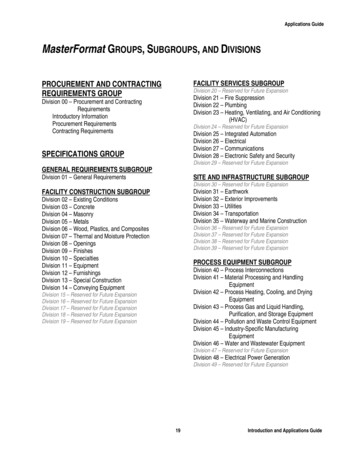
D7039 Installation Guide NoticesNotices1.0Use these instructions to install the D7039 MultiplexExpansion Module in a fire system supervised by aD7024 Fire Alarm Control Panel (FACP).The D7039 (Figure 1) connects directly to the FACP foreither two Class B multiplex buses or one Class Amultiplex bus that allows up to 247 remote points.Install, test, and maintain the D7039 according to theseinstructions, NFPA 72, local codes, and the AuthorityHaving Jurisdiction (AHJ).DescriptionFigure 1: D7039 Module Location1Follow the procedures in this document toavoid personal injury and damage to theequipment. Failure to follow theseprocedures can cause the D7039 to notoperate properly. Bosch is not responsiblefor improperly installed, tested, or maintaineddevices.2PowerAlarm41 2 34 5 67 8 9* 0 esetHistoryCmndFor the D7039 with ROM version 1.04 tooperate properly, the D7024 FACP must berunning version 2.05 or later firmware.1234-D7024 Control BoardEnclosureI/O module for the D7039D7039 ModuleWhen configured for Class A operation,the D7039 can only support Addresses 9through 128.2Bosch 09/05 38685F
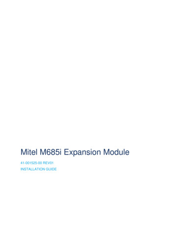
D7039 Installation Guide 2.0 Installation2.0InstallationFailure to follow the mounting instructions in this document can damage the FACP.The D7039 and D7024 have static sensitive components and must be handled with care. Follow theanti-static procedures when handling these modules.Before installing the D7039 Module, remove all AC and battery power to the FACP.1.If the D7024 is already installed in an enclosure, remove it.2. Place the FACP on a flat surface with the component side facing up (Item 2 in Figure 2).3. Insert the four plastic standoffs in the mounting holes (Item 3 in Figure 2) without bending or flexing the FACP.4. Align the standoff tabs so they do not touch the module components.5. Firmly press the standoffs into the board, allowing the ears to expand out.6. Mount the D7039 on the standoffs, ensuring the FACP connector pins (Item 4 in Figure 2) are properly aligned.7.Install the FACP in the enclosure.8. Use the mounting screw (Item 5 in Figure 2) to secure the D7039’s ground wire (Item 6 in Figure 2) to the FACP.Figure 2: Mounting the D7039 on the D702412PowerAlarmTroubleSilenced31 2 34 5 67 8 9* 0 nd51 - D7039 Module2 - D7024 FACP3 - Standoff mounting holes (4)Bosch 09/05 38685F4 - FACP connector pins to align with the D70395 - Mounting screw6 - Ground wire3
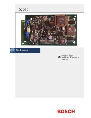
D7039 Installation Guide 2.0 Installation9. Mount the D7039 I/O Module (Item 1 in Figure 3) in the FACP enclosure (Item 2 in Figure 3) using the mountingholes in the enclosure (Item 3 in Figure 3).10. Connect the yellow and green earth ground wire from the I/O module to the earth ground terminal on theFACP control board (Item 4 in Figure 3).Figure 3: Installing the Input-Output Module12PowerAlarm1 2 34 5 67 8 9* 0 esetHistoryCmnd41 - I/O module3 - Holes (3) and standoffs (3) to mount the I/O module2 - Enclosure4 - I/O module earth ground wire to the D70243.01.terminal connectionWiringConnect the D7039 multiplex loop using up to 3800 ft (1170 m) of 18 AWG (1.0 mm2) or 5950 ft (1810 m) of16 AWG (1.5 mm2) wire (Figure 4). Do not use shielded wire.Do not use shielded wire. Twisted pair is acceptable, but is not recommended.Figure 4: Connecting the Mux Class “A” and Class “B”1 - I/O module for the D7039, wired Class “A”2 - Class “A” Addresses 9 through 1283 - I/O module for the D7039, wired Class “B”Note:44 - Mux B Addresses 129 through 2555 - Mux A Addresses 9 through 128All terminals are supervised.Bosch 09/05 38685F
D7039 Installation Guide 4.0 SpecificationsYou can configure the D7039 with a single fault tolerant Class “A” loop or as a pair of supervised Class “B”loops. When configured as a Class “A” loop and installed on a D7024 Control Panel before Lot #100, theD7039 implements a Style 4.5 signaling line circuit (SLC). When installed on a D7024 Control Panel Lot #100or later, the D7039 implements Style 6 SLC. Refer to the D7024 Operation and Installation Guide (P/N: 31499)for programming.When configured as a Class “B” loop and installed on a D7024 Control Panel before Lot #100, the D7039implements a Style 3.5 SLC. When installed on a D7024 Control Panel Lot #100 or later, the D7039implements a Style 4 SLC. Refer to the D7024 Operation and Installation Guide (P/N: 31499) for programming.2. Measure loop resistance by shorting the end of the farthest device in Class “B” (Figure 5) or shorting the returnwire in Class “A” (Figure 6) and reading the total resistance of all wires associated with the loop.Figure 5: Measuring Class “B” Loop Resistance1 - 50 Ω maximum2 - Mux bus wires3 - Clip lead3. Ensure the loop is disconnected from the D7039 Module.Figure 6: Measuring Class “A” Loop Resistance1 - 50 Ω maximumBosch 09/05 38685F2 - Mux bus wires3 - Clip lead5
D7039 Installation Guide Notes4.0SpecificationsTable 1:SpecificationsInput VoltageCurrent Draw, Standbyand AlarmCurrent Draw LoadMaximum Bus VoltageMaximum WiringResistanceEnvironment24 VDC nominal from FACP150 mA maximum100 mA maximum for each bus8.5 V to 13 V50 Ω, Class A (Style 6) or Class B (Style 4) SLCIndoor/dryNote: All Mux Bus terminals are power-limited and supervised.6Bosch 09/05 38685F
D7039 Installation Guide NotesNotesBosch 09/05 38685F7
Bosch130 Perinton ParkwayFairport, NY 14450-9199 USACustomer Service: (800) 289-0096Technical Support: (888) 886-6189 2005 Bosch38685F
or later, the D7039 implements Style 6 SLC. Refer to the D7024 Operation and Installation Guide (P/N: 31499) for programming. When configured as a Class "B" loop and installed on a D7024 Control Panel before Lot #100, the D7039 implements a Style 3.5 SLC. When installed on a D7024 Control Panel Lot #100 or later, the D7039 implements a .