Transcription
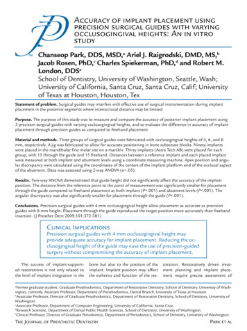
Accuracy of implant placement usingprecision surgical guides with varyingocclusogingival heights: An in vitrostudyChanseop Park, DDS, MSD,a Ariel J. Raigrodski, DMD, MS,bJacob Rosen, PhD,c Charles Spiekerman, PhD,d and Robert M.London, DDSeSchool of Dentistry, University of Washington, Seattle, Wash;University of California, Santa Cruz, Santa Cruz, Calif; Universityof Texas at Houston, Houston, TexStatement of problem. Surgical guides may interfere with effective use of surgical instrumentation during implantplacement in the posterior segments where interocclusal distance may be limited.Purpose. The purpose of this study was to measure and compare the accuracy of posterior implant placement using3 precision surgical guides with varying occlusogingival heights, and to evaluate the difference in accuracy of implantplacement through precision guides as compared to freehand placement.Material and methods. Three groups of surgical guides were fabricated with occlusogingival heights of 4, 6, and 8mm, respectively. A jig was fabricated to allow for accurate positioning in bone substitute blocks. Ninety implantswere placed in the mandibular first molar site on a manikin. Thirty implants (Astra Tech AB) were placed for eachgroup, with 15 through the guide and 15 freehand. Distances between a reference implant and each placed implantwere measured at both implant and abutment levels using a coordinate measuring machine. Apex position and angular discrepancy were calculated using the coordinates of the centers of the implant platform and of the occlusal aspectof the abutment. Data was assessed using 2-way ANOVA (α .05).Results. Two-way ANOVA demonstrated that guide height did not significantly affect the accuracy of the implantposition. The distance from the reference point to the point of measurement was significantly smaller for placementthrough the guide compared to freehand placement at both implant (P .001) and abutment levels (P .001). Theangular discrepancy was also significantly smaller for placement through the guide (P .001).Conclusions. Precision surgical guides with 4-mm occlusogingival height allow placement as accurate as precisionguides with 8-mm height. Placement through the guide reproduced the target position more accurately than freehandinsertion. (J Prosthet Dent 2009;101:372-381)Clinical ImplicationsPrecision surgical guides with 4-mm occlusogingival height mayprovide adequate accuracy for implant placement. Reducing the occlusogingival height of the guide may ease the use of precision-guidedsurgery without compromising the accuracy of implant placement.The success of implant-supported restorations is not only related tothe level of implant integration in thebone but also to the position of theimplant. Implant position may affectthe esthetics and function of the res-toration. Restoratively driven treatment planning and implant placement require precise assessment ofFormer graduate student, Graduate Prosthodontics, Department of Restorative Dentistry, School of Dentistry, University of Washington; currently, Assistant Professor, Department of Prosthodontics, Dental Branch, University of Texas at Houston.bAssociate Professor, Director of Graduate Prosthodontics, Department of Restorative Dentistry, School of Dentistry, University ofWashington.cAssociate Professor, Department of Computer Engineering, University of California, Santa Cruz.dResearch Scientist, Department of Dental Public Health Sciences, School of Dentistry, University of Washington.eClinical Professor, Director of Graduate Periodontics, Department of Periodontics, School of Dentistry, University of Washington.aThe Journal of Prosthetic DentistryPark et al
373June 2009the surgical site. It must relate the desired type and 3-dimensional locationof the prospective restoration to thenecessary implant location. That position must be communicated from therestorative dentist to the surgeon.1 Asurgical guide is an effective methodto accomplish communication of thegoal.Surgical guides for implant placement have been used to enhance accurate positioning of implants. Manytypes of surgical guides have beendeveloped and used in dentistry.Generally, the surgical guide fabrication process begins with a diagnostictooth positioning, either through adiagnostic waxing, denture teeth arrangement, or via the duplication ofthe preexisting dentition/restoration.2Fabrication techniques may vary inthe manner of transferring such diagnostic information to a surgical guideand the guide’s application duringsurgery. Surgical guides may be categorized based on the material usedand amount of surgical restriction.Clear vacuum-formed matrices,3 withor without the use of autopolymerizedacrylic resin,4 and gutta-percha5 ormetal rods6-8 for contrast and radiographic assessment, have been usedin the past. Autopolymerized acrylicresin has also been widely used for thefabrication of surgical guides. Pareland Funk9 made acrylic resin guideswith facial contours, only. Akca et al10used a channel guide placed into anautopolymerized acrylic resin guide.Sicilia et al11 placed 2 wires occlusally and gingivally, which were bentfollowing the facial contour of theproposed restoration in the edentulous area. The authors used autopolymerized acrylic resin to secure thesewires in the dentate area. These wireswere used to maximize the visibilityof the surgical site instead of acrylicresin. Other materials, such as lightpolymerizing composite resin traymaterial12 or a combination of acrylicresin and composite resin, have beenused as alternatives, as well.13 Morerestricted types of guides were alsointroduced to guide drills with sleevesPark et alor channels. Burns et al14 set metaltubes in the guide using a surveyorat the proposed center of restoration with the desired angulation andused acrylic resin to fix the tubes inplace. Disks and incremental tubesor channels were also used to guidedrills sequentially.15-19 Cehreli19 used2-, 3-, and 3.8-mm incremental tubesin acrylic resin surgical guides alongwith computerized tomography (CT)derived data.Recently, new surgical guides havebeen developed for precise implantplacement, so that a definitive or aninterim prosthesis may be fabricatedprior to surgery. Precision surgicalguides may be defined as metallicguides closely matched to the diameter of the drills and/or implants. Theseguides are fabricated with the aid ofcomputer-assisted design/computerassisted manufacturing (CAD/CAM)technology and rapid prototyping.20,21CAD/CAM-generated surgical guidesin conjunction with cone-beam computerized tomography (CBCT) haveexpanded the possibilities in terms ofpresurgical treatment planning andaccurate implant placement. Severalarticles were recently published on theaccuracy of computer-aided implantsurgery.22-30 Two different techniqueshave been developed for computeraided implant surgery: stereolithographic surgical guide techniques andnavigation using optical tracking techniques. Ruppin et al22 evaluated theaccuracy of 2 optical tracking systemsand 1 stereolithographic guide in vitrousing human mandibles. They foundno significant difference in the accuracy of implant placement using the3 systems. All 3 groups showed meandeviation of no more than 1.5 mmbuccolingually and 0.8 mm in vertical depth. Wanschitz et al24 showeda mean of 0.96 mm lateral deviationusing the optical tracking technique.Sarment et al31 compared a conventional guide, which was modified froma radiographic guide, to a stereolithographic surgical guide using CBCT invitro. Results showed that the meandistance between the planned implantplacement and the actual osteotomywas significantly smaller for the stereolithographic guide as compared tothe conventional one. van Steenberghe et al32 examined the accuracy ofa CAD/CAM surgical guide in cadavers, and Vrielinck et al33 performed asimilar study in human subjects. In areview article, Vercruyssen et al30 discussed possible errors of CAD/CAMsurgical guides, which may occur atany of the following stages: CT-scandata collection, positioning of theradiographic guide, segmentation ofbone, teeth, and/or tissue from thecomplete image, stereolithographicor CAD/CAM modeling, fixation ofthe surgical guide to the jaw bone,and use of precision sleeves. This typeof precise surgical guide has also presented some challenges to clinicians.Yong and Moy34 studied early complications using CAD/CAM-guided implant placement with the NobelGuidesystem (Nobel Biocare AB, Göteborg,Sweden). The authors found that themost common early surgical complication was incomplete seating of theprosthesis due to bony interferences.Limited surgical access with surgical guides intraorally may be one ofthe most common challenges of usingsurgical guides. Surgical guides mayinterfere with effective use of surgicalinstruments in the posterior segmentswhere interocclusal distance may belimited, especially for the partiallyedentulous patient. It is not uncommon that the surgical guide may beused only for the initial marking of thecenter, or for a portion of the osteotomy. Thus, surgical guides for implantplacement should be designed notonly as a precise and effective communication tool, but also to occupyminimum space so as not to interferewith the surgery. Choi et al35 evaluatedthe effects of varied dimensions of surgical guides on implant angulations.The authors evaluated 3 variables,including the diameter of the surgicalchannels, the length, and the distancefrom the recipient site to the guide.The length of the channel seemed tobe the primary controlling factor in
374Volume 101 Issue 6minimizing angular deviation. Choiet al35 recommended the use of thelongest channel possible. The study,however, was not conducted with anincremental drill guide system thatcorresponds to the sequential drill diameters.The purpose of this in vitro studywas to measure and compare the accuracy of implant placement in themandibular molar region using 3 precision surgical guides with varying occlusogingival heights, and to evaluatethe difference in accuracy of implantplacement through the guides as compared to freehand placement. The research hypotheses were: (1) the occlusogingival height of the guide doesnot affect the accuracy of implantplacement, and (2) guided implantplacement is as accurate as freehandimplant placement.MATERIAL AND METHODSThree groups of metal guides (35mm (L) x 10 mm (W)) with varying occlusogingival heights (4, 6, and 8 mm)were fabricated. Three holes were precisely drilled into metal blocks withdiffering heights to fabricate the surgical guides. Two holes, 1 on each end,were used as positioning references forthe guides. The diameter of these holeswas 5.5 mm. The hole at the center,5.7 mm in diameter, correspondingto the implant carrier (Facilitate; Astra Tech AB, Mölndal, Sweden), wasused for aligning each drill sleeve andfor implant placement (Fig. 1). Threeguides were precisely machined tohave identical dimensions except theirheights, with 0.0002-inch machining tolerance (Bridgeport V2XT CNCMilling Machine; Hardinge, Inc, Elmira, NY). The guides were designed toslide over a metal jig that had 2 vertical beams with a diameter of 5.5 mmon a rectangular metal base. On eachbeam, a setting pin hole was drilledso that the setting pins could be positioned to stop the guides at the samevertical position. The setting pins weredesigned to be located 3 mm above apolyurethane bone substitute block(Pacific Research Laboratories, Inc,Vashon Island, Wash). A 3-mm-diameter V-shaped crater was machined ontop of each beam to be used as a measurement reference (Fig. 2).Bone substitute blocks were madeof rigid polyurethane foam with adensity of 0.48 g/cc. The dimensionsof the blocks were 37 mm (L) x 14 mm(W) x 16 mm (H). Each block had 2holes to fit the metal jig (Fig. 3). Theblocks were designed to fit the metaljig with friction to minimize positioning errors. A drill guide was machinedout of stainless steel and used to makepositioning holes on the bone substitute block.A typodont (ModuPRO Pros;Acadental, Inc, Woodson, Kan) wasmounted in a manikin, and the metaljig was placed on the base of the ty-1 Surgical guides with varying occlusogingival heights (8mm, 6 mm, and 4 mm).The Journal of Prosthetic Dentistrypodont. The bone substitute blockwas placed onto the metal jig. Subsequently, the setting pins, made of1-mm-diameter stainless steel rods,10 mm in length, were placed ontothe metal jig. One of 3 guides waspositioned on top of the setting pins,leaving 3 mm of space between thebone substitute block and the guide.Plastic teeth in the mandible and themaxilla enhanced the simulation ofactual surgery (Fig. 3).Each guide group (4-mm, 6-mm,and 8-mm groups) was divided into2 subgroups: the guided placementgroup and the freehand placementgroup. In this study, guided placementwas defined as implant placement using the Facilitate (Astra Tech AB) implant carrier which fit the internal diameter of the surgical guide channel.Freehand placement was defined asimplant placement using a regular implant carrier without a surgical guideafter the osteotomy was prepared.Both groups used identical proceduresfor the drilling stages. For each of thesubgroups, 15 implants were placed,for a total of 90 implants (OsseoSpeed demonstration implants, 4.0 x11 mm; Astra Tech AB) (Table I).A reference implant (OsseoSpeeddemonstration implant, 4.0 x 11 mm;Astra Tech AB) was connected to theFacilitate implant carrier (Astra TechAB). This assembly was placed at thecenter hole of the metal guide. The diameter of the center hole in the metal2 Metal jig (37 mm (L) x 14 mm (W) x 3 mm (H)) withV-shaped crater on top of vertical beams for measuringreferences and with setting pin holes to stop guides atsame vertical position.Park et al
375June 20093 Assembly of metal jig, bone substitute block, setting pins, and surgical guide.Table I. Descriptive statisticsMethod of ImplantPlacementHeight ofGuide8 mmFreehand0.45 (0.15)0.63 (0.35)0.04 (0.02)0.730.731.280.080.49 (0.17)0.54 (0.19)0.61 (0.26)0.03 (0.02)0.800.801.000.070.40 (0.18)0.55 (0.23)0.74 (0.23)0.06 (0.02)0.711.091.130.09Average of means0.43 (0.18)0.52 (0.19)0.66 (0.28)0.04 (0.02)8 mm0.25 (1.00)0.28 (0.15)0.47 (0.28)0.03 (0.02)0.400.691.050.080.26 (0.13)0.28 (0.12)0.41 (0.24)0.03 (0.01)0.570.490.820.050.24 (0.08)0.29 (0.12)0.37 (0.15)0.03 (0.01)0.370.550.650.060.25 (0.10)0.28 (0.13)0.42 (0.23)0.03 (0.01)6 mm6 mm4 mmAverage of meansguide was designed to fit this carrier. Ametal tube with an internal diameterof 5.5 mm was placed on each verticalbeam. Autopolymerizing resin (Pattern Resin; GC America, Inc, Alsip, Ill)was used to connect this metal tubeto the implant, which was already assembled to the Facilitate carrier (Fig.4). The discrepancy from this refer-Park et alAngle (Degrees)0.38 (0.18)4 mmGuidedMean (SD)MaximumImplant Level (mm) Abutment Level (mm) Apex (mm)ence implant to each implant specimen was measured and compared.One operator followed a standarddrilling protocol as recommended bythe manufacturer. A round bur and a2-mm twist drill, a 3.2-mm twist drill,and a 3.7-mm twist drill were sequentially used with the correspondingprecision guide sleeves (Fig. 5). Sinceeach drill sleeve was 5 mm in height,only the distance to the bone substitute block varied during drilling. Themetal guide itself directed the implantplacement; thus, the height of theguide influenced the entire placementphase. Each drill guide insert, 5 mm inheight, had a 1-mm-thick metal flange,which was used as a vertical stop. Each
376Volume 101 Issue 64 Reference implant.5 Facilitate drill guide used for drilling.AB6 A, Guided implant placement with Facilitate implant carrier. B, Freehand implant placement with conventional implant carrier.set of drills was used for 15 sites anddiscarded. Vertical depth of drillingfor each guide group was preplannedso that the osteotomy finished at thesame vertical depth into the bone substitute block for each group of guides.For the 4-, 6-, and 8-mm guide groups,the total length of drilling was 19 mm,21 mm, and 23 mm, respectively,measuring from the top of the drillguide insert. Drilling was executed at1500 rpm (WS-75 E/KM contra-anglehandpiece, Implantmed motor; W &H Dentalwerk, Bürmoos, Austria). Forthe guided implant placement group,implant placement was performedthrough the guides using the implantcarrier (Fig. 6, A). For the freehandplacement group, the guide was removed after the completion of the osteotomy, and a conventional implantcarrier was used to place the implant,with the 2 vertical beams of the metaljig used as direction guides for placement (Fig. 6, B). A torque of 25 Ncmwas used for placement. If the motorstopped in the middle of the implantplacement procedure, the torque wasincreased to 35 Ncm, and then a manual wrench was used to complete theplacement. All procedures were performed on the manikin to simulate aclinical scenario (Fig. 7).The base of the typodont was fixedwith screws to a flat wooden plate,and a coordinate measuring machine(CMM) (Microscribe MX System; Immersion Corp, San Jose, Calif ) wasfixed to the same plate, so that bothwere on the same plane. The metal jigwas secured to the base of the typodont using light-polymerized composite resin (Triad VLC Custom Tray Material; Dentsply Trubyte, York, Pa). Byfixing the typodont and the CMM onthe same plane, the metal jig and theCMM had the same spatial relationship throughout the measurementsand maintained the same orientation.The center of the implant wasThe Journal of Prosthetic Dentistrymeasured at the implant level andabutment level using the CMM, whichis accurate to less than 0.002 inches(0.05 mm) (Fig. 8). A sapphire ballprobe (Microscribe MX System; Immersion Corp), 3 mm in diameter, wasplaced on the top of the mesial vertical beam, and this position was setas the customized reference position.The CMM recognized this position as(0, 0, 0) in space. An imaginary lineconnecting the center of the mesialand distal beam was taken as the xaxis (distal direction as ). The rightangle to this axis was taken as the yaxis (buccal side as direction). Vertical to this x-y location from the homeposition was the z axis (occlusal direction as ).The reference implant block wasplaced and measured at the implantlevel. Each measurement was made 5times and averaged. The same measurement was made after connectinga temporary abutment (TemporaryPark et al
377June 20097 Simulation manikin with attached assembly.AB8 A, CMM (Microscribe) used to measure coordinates of implant at implant level. B, Abutment level.Abutment 3.5/4.0; Astra Tech AB)to the implant. This measurementwas used as a reference position, andall other measurements made of the90 specimens were compared to thisposition for each implant level andabutment level. The apex and angular discrepancy of the implants weremathematically calculated and compared using the 2 known coordinatesof the implant and the abutment.Two-way ANOVA was used for statistical analysis. Level of significance (α)was set to .05 for all of the tests. Allcalculations were made using a statistical software package (SPSS 12.0;SPSS, Inc, Chicago, Ill).RESULTSDescriptive data showed that themean (SD) and maximum deviation(Max) at the implant level for each ofthe 4-mm, 6-mm, and 8-mm guidedplacement groups were 0.24 (0.08)mm, 0.26 (0.13) mm, and 0.25 (0.10)Park et almm, respectively. The average of thesemeans was 0.25 (0.10) mm (Max: 0.57mm). At the abutment level, they were0.29 (0.12) mm, 0.28 (0.12) mm, and0.28 (0.15) mm for each of the 4-mm,6-mm, and 8-mm guide groups, respectively. The average of these meanswas 0.28 (0.13) mm (Max: 0.69 mm).At the apex level, the average mean ofthe 3 guide groups for guided placement was 0.42 (0.23) mm (Max: 1.05mm). The average mean angular discrepancy of the 3 guide groups forguided placement was 0.03 (0.01) degree. However, for the freehand placement group, the average of the means(SD) of the 3 guide groups and maximum deviation (
group, with 15 through the guide and 15 freehand. Distances between a reference implant and each placed implant were measured at both implant and abutment levels using a coordinate measuring machine. Apex position and angu-lar discrepancy were calculated using the coordinates of the centers of the