Transcription
Architectures for Real-Time Volume RenderingHanspeter PfisterMitsubishi Electric Research, 201 Broadway, Cambridge, MA 02139, U.S.A.pfister@merl.comAbstractOver the last decade, volume rendering has become an invaluable visualization techniquefor a wide variety of applications. This paper reviews three special-purpose architecturesfor interactive volume rendering: texture mapping, VIRIM, and VolumePro. Commercialimplementations of these architectures are available or underway. The discussion of eacharchitecture will focus on the algorithm, system architecture, memory system, and volumerendering performance.Color pictures are available at http://www.elsevier.nl/locate/future.Key words: Computer Graphics, Volume Rendering, Hardware Architecture, GraphicsProcessors, Special-purpose and Application-level Systems1 IntroductionVisualization of scientific, engineering or biomedical data is a growing field withincomputer graphics. In many cases, the objects or phenomena being studied are volumetric, typically represented as a three-dimensional grid of volume elements, orvoxels. Examples of volume data include 3D sampled medical data (CT, MRI),simulated datasets from computational fluid dynamics, or computed finite elementmodels. One of the key advantages of volumetric data is that, unlike surface-basedrepresentations, it can embody interior structure of the objects. Additionally, operations such as cutting, slicing, or tearing, while challenging for surface-based models, can be performed relatively easily with a volumetric representation [Gib97].Volume rendering generates images directly from the volume data without intermediate surface models. It allows the display of internal structures, including amorphous and semi-transparent features. Voxels are either processed in image-order orobject-order to generate an image. Image-order algorithms iterate over all pixels ofthe output image and determine the contributions of voxels towards each pixel. Raycasting is the most commonly used image-order technique [Lev88]. Rays are castPreprint submitted to Elsevier Preprint7 August 1998
from the viewpoint into the volume and the contributions of voxels along each rayare used to determine pixel colors. Object-order algorithms iterate over the volumedata and determine the contribution of each voxel to the pixels. A typical objectorder technique is splatting, which convolves every voxel with a 3D reconstructionfilter and accumulates the voxels contribution on the image plane [Wes91].While volume rendering is a very popular visualization technique, the lack of interactive frame-rates has limited its widespread use. Volume rendering is very memory and computation intensive. To render one frame typically takes several seconds. Highly optimized software techniques for volume rendering try to addressthis problem by using pre-processing to compute, for example, object illumination or regions of the volume that can be skipped during rendering [LL94,Lev90].However, pre-processing prohibits immediate visual feedback during parameterchanges. Each time rendering parameters such as voxel transparency or illumination are changed, the lengthy pre-processing must be repeated before the new imageis displayed. Furthermore, the pre-computed values typically increase the storagerequirements by a factor of three to four.To overcome these limitations, several Universities (e.g., University of Mannheim[GPR 94], University of Tübingen [KS94,KS97], State University of New Yorkat Stony Brook [PK96,BK97]) and companies (e.g., Mitsubishi Electric [OPL 97]and Japan Radio Corporation) have undertaken the development of special-purposehardware for volume rendering. Hardware accelerators aim to provide real-timeframe rates, typically defined to be between 10 and 30 frames per second. Realtime visual feedback allows for interactive experimentation with different rendering parameters. In addition, because hardware does not require pre-processing, itallows visualization of dynamically changing volume data, such as data from interactive tissue cutting during surgical simulation, or continuous data input from 3Dultrasound.The next section presents general issues related to the design of high-performancevolume rendering architectures. The focus is on the design of high-bandwidth memory systems which are the basis for all architectures presented in this paper. Sections 3 through 5 present the architectures of texture mapping, VIRIM, and VolumePro, respectively. Section 6 concludes the paper with a brief summary of themain features of these architectures.2 Architectural ChallengesThe computational demands of volume rendering require the use of a high degreeof hardware parallelism. Pipelining and unit replication are the two main formsof parallelism found in most high-performance architectures. A pipeline consistsof a sequence of stages through which a computation and data flow. New data is2
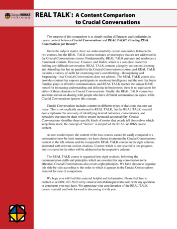
input at the start of the pipeline while other data is being processed throughout thepipeline. Unit replication refers to using multiple processing units, each workingon a different stream of data. Combining pipelining and unit replication by usingparallel processing pipelines achieves a high level of parallelism and performance.Important issues are the interconnections and data paths between stages of differentpipelines.Because volume rendering is memory intensive, the design of the memory system is critical in volume rendering architectures. The memory systems includesa suitable memory hierarchy, fast memory caches, and memory bus architecture.A determining factor of the maximum achievable memory bandwidth is the performance of dynamic random-access memory (DRAM), the fundamental buildingblock of all memory systems. In the last 30 years the speed of microprocessors hasincreased 1000-fold whereas the speed of DRAM has only increased by a factorof 20 [Sak97]. As shown in Figure 1, recent architectural improvements to DRAMmodules have increased their sequential access bandwidth [Kat97]. However, theirrandom access performance remains low and approximately constant across different DRAM technologies.Sequential AccessRandom AccessMemoryBandwidth1000 MB/s600125100 MB/s10 MB/s502911Fast PageMode DRAM11EDODRAM12.5SDRAM16RambusFig. 1. This graph plots memory bandwidth (in MBytes per second, logarithmic scale) fordifferent DRAM technologies. Fast page mode DRAM allows fast access to an entire row(called a page) of the internal memory array. Extended data out DRAM (EDO DRAM)includes an extra pipeline stage in the output buffer. Synchronous DRAM (SDRAM) hasa high-speed synchronous interface and multiple internal memory banks. Rambus DRAMuses a high-speed packet-type memory interface.A common method to increase memory bandwidth for regular, systematic access todata is a technique called interleaving. The idea is to subdivide the data into smallersubsets that can be distributed uniformly among different physical memories. Thesimplest and most common form of interleaving is called low-order interleaving[Fly95]. It assigns successive memory addresses to distinct memory modules. Form memory modules, enumerated from 0 to (m , 1), memory address a is assignedmemory module number k a mod m.3
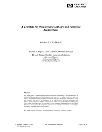
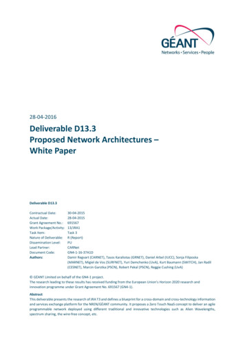
Figure 2 shows the resulting partitioning of the address space across memory modules. The index i into the memory module is calculated as i b ma c, where bc indi-Index210Memory Module2m2m 12m 23m-1mm 1m 22m-1012m-1012m-1ModuleNumberFig. 2. Low-order interleaved memory system with m memory modules. Memory address ais assigned to memory module k according to k a mod m.cates the floor, or the next lower integer, of the expression. The number of memorymodules in an interleaved memory system is called the degree of interleaving. Alternatively, a memory system is said to be m-way interleaved.Notice in Figure 2 that voxels are stored successively in rows across the memory.Low-order interleaved memory performs best for consecutive row access, but performance breaks down for column access. Accesses against the storage order mayoccur frequently in volume rendering, for example, in object-order algorithms. Onesolution is to store the dataset three times, once for each main axis [LL94]. However, data duplication increases the high storage requirements of volume rendering.The architectures surveyed in this paper implement interleaved memory systemsthat support high-bandwidth access to volume data without pre-processing and dataduplication. The remainder of this paper describes texture mapping hardware, theVirtual Reality in Medicine (VIRIM) system, and Mitsubishi’s VolumePro system.We discuss the algorithms these systems implement, their system architectures withemphasis on the memory system, and their volume rendering performances.3 Texture Mapping HardwareTexture mapping hardware is a common feature of modern 3D polygon graphics accelerators. It can be used for volume rendering by applying a method called planartexture resampling [CCF94]. The volume is stored in 3D texture memory and resampled during rendering by extracting textured planes parallel to the image plane(see Figure 3). Lookup tables map density to RGBA color and opacity. The resulting texture images are combined in back-to-front visibility order using compositing[PD84]. Each texture sample is assigned an opacity, called the alpha component.4
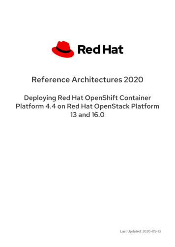
Texture SlicesImage PlanePoint of Viewa) Object-spaceSample Planesb) Image-spaceSample PlanesFig. 3. Planar texture resampling.An alpha of 1.0 implies a fully opaque sample, and an alpha value of 0.0 implies afully transparent sample. When two texture images are combined, the backgroundcolor is blended with the foreground color using the alpha component to linearlyinterpolate between the colors.High-quality shading effects of the volume object require gradients which reflectthe rate and direction of change in the volume data. Most volume rendering algorithms use the central difference gradient, which is computed by local differencesbetween voxel values in all three dimensions [HB86]. Using these gradients, a localillumination model is applied to each texture sample to shade the volume object.Figure 4 shows several texture mapped images of a wrist rendered with differentgradient methods.(a) No Shading(b) Slice Subtraction(c) Edge Filtered(d) Central DifferencesFig. 4. Several renderings of a wrist dataset (256 256 53) using texture mapping hardware and multi-pass gradient estimation. a) 1 pass: No shading. b) 2 passes: Slices of gradients are calculated by subtracting co-planar texture slices, one shifted in direction of thelight source. c) 3 passes: Gradients are resampled from a separate edge filtered volume. d)10 passes: Gradients are estimated using central differences between axis aligned textureslices in all three dimensions. Images courtesy of David Heath, Johns Hopkins University.5
Texture engines do not directly support estimation of gradients or per-sample illumination in hardware. Gradients are typically pre-computed and stored in an additional volume or are computed on-the-fly using multi-pass methods. However,multi-pass rendering and shading in software greatly reduce the achievable framerate. An alternative is to use a shading approximation by pairwise subtracting coplanar texture slices, one shifted in direction of the light source [PAC97].System ArchitectureTexture mapping hardware is part of the raster graphics rendering pipeline shownin Figure 5 [FvDFH90]. During planar texture resampling, the geometry processorTexture terizerDisplayFig. 5. Texture mapping system architecture.computes the texture coordinates of each vertex of a resampling slice. The rasterizer is connected to the texture engine which resamples the texture data stored intexture memory using tri-linear interpolation. The resampled texture slices are thenaccumulated into the frame buffer using compositing [PD84].High-performance 3D graphics engines, such as the SGI Reality Engine [Ake93],use eight-way interleaved texture memory. Tri-linear interpolation requires a cellof eight adjacent voxels. Eight-way memory interleaving allows the texture engineto fetch any tri-linear cell in one memory access. A voxel with address a [zyx]is stored in memory module k at index i as follows:k (x mod 2) 2 (y mod 2) 4 (z mod 2);i b x2 c 2 b y2 c 4 b z2 c:(1)Figure 6 shows the resulting assignment of voxels to memory modules in threedimensions.Texture PerformanceThe best published texture rendering performances have been achieved on SGI Reality Engine 2 systems with multiple texture engines or Raster Managers (RMs).Hemminger et. al [HCN94] report a series of results with two RMs, rendering a256 256 32 volume at 12 frames per second. Cabral et al. [CCF94] use fourRMs to render a 512 512 64 dataset at 10 frames per second. These resultstranslate roughly into a maximum performance of 160 million unshaded tri-linear6
1111Memory Module 000000001
Architectures for Real-Time Volume Rendering Hanspeter Pfister Mitsubishi Electric Research, 201 Broadway, Cambridge, MA 02139, U.S.A. pfister@merl.com Abstract Over the last decade, volume rendering has become an invaluable visualization technique for a wide variety of applications. This paper reviews three special-purpose architectures for interactive volume rendering: texture mapping .