Transcription
Risk-Based Analysis and Engineeringof Safe Distances Between OccupiedStructures and Processing EquipmentJ. E. Johnstone, M. D. Spangler, C. S. Heitzman, G. A. Wimberley, and A. R. Flores, Contek SolutionsSummaryDetermining the optimal distance between explosive, flammable,and toxic hydrocarbon sources and occupied structures is a constant concern for engineers working to design safe facilities. Overthe years, many incidents have occurred during which workerswere injured or killed by flying shards of glass and debris, explosive forces, fire, or exposure to toxic gases when occupied structures were not located properly in relation to process equipment.This paper presents newly developed techniques to allow the engineer to locate occupied structures optimally to ensure that the riskof harm to personnel is minimized.The analysis of determining the placement for an occupiedstructure involves many variables that the engineer must evaluate.These variables include the properties of the hydrocarbons that arebeing processed, toxic components (e.g., hydrogen sulfide), operating parameters, loss-of-containment scenarios, prevailing winds,occupancy loads, building construction, safety systems, and operating and maintenance practices. Each of these different variablescan have a significant impact on where a building should be located within or adjacent to a facility. The engineer must considerthese variables for impacts to the structure caused by fire, blast, ortoxic-gas infiltration.Recognized industry best practices and regulatory requirementsrequire that blast loads, which commonly present the most-severehazard to a building, be evaluated when locating an occupied structure. Often, it is not practical to design or locate a building to withstand the “worst-case” blast scenario. For this reason, a risk-basedapproach, in conformance with recognized best practices, has beendeveloped to site buildings properly at oil and gas facilities.This paper presents a viable risk-based approach for the sitingof occupied structures at oil and gas facilities. The technique presented in the paper enables the engineer to gather the informationneeded for the analysis quickly, evaluate credible scenarios, andthen make the necessary calculations to determine impacts to theoccupants. The result of using this technique is that an occupiedstructure is located properly and constructed to reduce the risk ofharm to the occupants to a tolerable level.IntroductionThe siting of buildings at upstream and midstream oil and gas facilities is described in API RP 752, Management of Hazards Associated with Location of Process Plant Permanent Buildings(2009). Buildings covered by this recommended practice includerigid structures intended for permanent use in fixed locations. APIRP 752 (2009) sets the bar for recognized and generally acceptedgood-engineering practices for the oil and gas industry.Copyright 2015 Society of Petroleum EngineersThis paper (SPE 173507) was accepted for presentation at the SPE E&P Health, Safety,Security, and Environmental Conference—Americas, Denver, 16–18 March 2015, andrevised for publication. Original manuscript received for review 18 December 2014. Revisedmanuscript received for review 24 February 2015. Paper peer approved 19 March 2015.48Oil and Gas Facilities August 2015API RP 752 (2009) allows for the evaluation of building locations to use three different assessment approaches:1. Consequence-based analysis: This approach generally requires that the impacts from maximum credible events(MCEs) be calculated or modeled to determine the impacton a structure.2. Risk-based analysis: Use of risk-based analysis involvesconducting a quantitative analysis to determine risk onthe basis of the consequence and the frequency of the hazardous event.3. Spacing-tables approach: Under API RP 752 (2009), thespacing-table approach is to be used only when determiningthe minimum distance from a fire to a building. These tablesare not appropriate for toxic or explosive events for which theconsequence is dependent on the release rate, length of release,wind direction, material released, and many other factors.API RP 752 (2009) was developed primarily for use at facilities that include natural-gas plants, natural-gas-liquefication plants,and other onshore facilities covered by the Occupational Safety andHealth Administration (OSHA) process-safety management standard (OSHA 1992). API RP 752 (2009) provides an excellent overview of the issues and factors regarding hazards associated withbuildings and provides references as to where additional information can be obtained. The recommended practice does not provideinformation relating to an oil-production or a gas-treatment facility,detailing out critical items such as MCEs, impacts from hazardousincidents, acceptatble risk criteria, and risk analaysis.The objective of this paper is to present a detailed approach thatcan serve as the basis for determining safe distances between buildings and processing equipment.Consequence-Based AnalysisA consequence-based analysis should be conducted first to determine if a structure can be impacted by an explosion, toxic release,or a fire. This technique looks at the on-site “manned” structuresand the hazards presented by process equipment and storage vessels on occupied buildings. Modeling software can use pure chemicals or mixtures for its dispersion modeling. The dispersion modelsare created by use of a wind blowing directly toward the equipmentto the building under analysis to determine the worst case. The instructions given in API RP 752 (2009) should be strictly followedfor determining impacts on any buildings. This analysis reveals thepresence of any underlying proximity issues and offers specificscenarios and their related impacts, in addition to identifying thehighest consequence each piece of equipment presents.For existing buildings, it may be found that a building will provide either enough protection for the occupants or not. New buildings must be designed to protect the occupants on the basis ofthe results of the impacts from the hazardous event. A mitigationplan must be developed for existing buildings that do not meet thesiting-evaluation criteria.Mitigation measures are categorized as being passive, active, orprocedural. These measures may require the operator to eliminateAugust 2015 Oil and Gas Facilities1
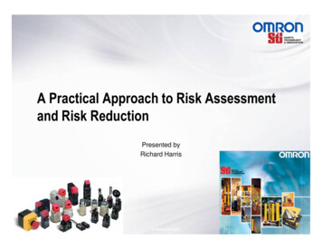
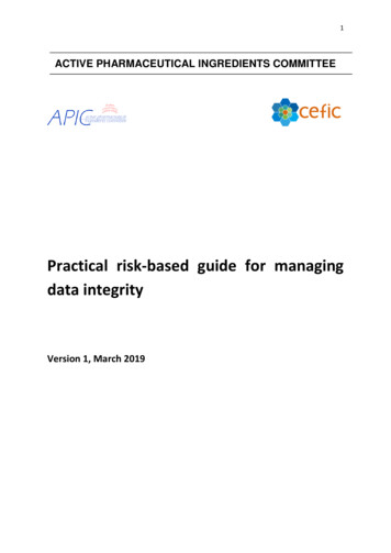
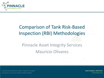
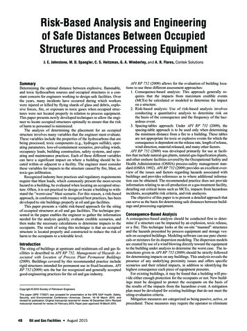
01234567829 10 11 12 13 14 15 16 17 18 19 20 21 22 23 24 25 26 27 28 29 30 31 32 33 34 35LPG Storage1PigReceivers345LPG Loading62,000-ft2Control Roomand 8NGL and Water Loading1920Dehydrator2122NORTHFlareNGL and WaterStorage232425Fig. 1—Site layout.the hazard, prevent or control the size or the release, and/or mitigate effects to the building occupants. Mitigation measures canprove to be very costly and often difficult to implement, particularly for older facilities.Risk-Based AnalysisThe risk-based analysis delves deeper than the consequence-basedanalysis by estimating the probability of each consequence and therisk value for each scenario. This analysis accounts for the hourlyoccupancy of each building and attempts to encompass all potential hazards presented at the facility. Modeling of multicomponentstreams can be developed, if required, to better model dispersiongiven a loss of containment. All cardinal and ordinal wind directions are used in the modeling process, along with different windspeeds (calm, average, and gusts). An in-depth loss-of-containmentevent tree is developed to calculate the probability of failure foreach hazardous piece of equipment, and once combined with themodeling consequences, the risk can be estimated. The effectiveness of the operator’s current safeguards and mitigation measuresare accounted for in the event tree and help provide a quantitativevalue of their safety. The resulting risk values are then comparedwith the operator’s accepted-risk matrix.If the risk is determined to be outside of the operator’s acceptable-risk range, recommendations will then be developed. Therecommendations are intended to reduce and manage the risk toan acceptable level. The analysis will provide the risk-reductionvalues of each recommendation so that no further analysis is required once the operator has implemented each of the recommendations successfully.Step-by-Step Process for Determining Safe BuildingLocationThe example problem presented in this paper is intended to guidethe user in conducting a building-siting study by use of both theconsequence-based approach and the quantitative risk-analysis(QRA) approach.For this example, the objective is to locate a 2,000-ft2 controlroom/office and a similar-sized warehouse on a location measuring350 250 ft (2 acres). The initial plot plan shows the building to be2Oil and Gas Facilities August 2015located opposite the processing equipment with the distance maximized for the size of the pad. The operator has specified that thebuildings will be constructed of reinforced concrete, which is designed and built to withstand a 3.5-psi blast pressure. A thermalflux tolerance of 10 kW/m2 will also be specified for the building,indicating that no exposed wood will be used in its construction.At the site, there will also be a produced-gas-conditioning facility consisting of compression, dehydration, and produced-liquidsremoval. A mixed stream of propane and butane [liquefied petroleum gas (LPG)] will be stored in pressurized “bullet” tanks. Thepentane and heavier hydrocarbons [natural-gas liquids (NGLs)]will be stored in 300-bbl atmospheric tanks. All liquids will betrucked from the site. The plot plan is shown in Fig. 1, where GPUmeans gas-processing unit.Step 1: Determine Buildings To Be Included in the Analysis. Allbuildings intended for occupancy should be included in the analysis. Typically, these include control rooms, offices, change houses,guard houses, shops, conference rooms, warehouses, and buildingsthat may become occupied over time or during an emergency. Athorough review of all existing buildings should be completed toensure that “local” work areas do not become established in buildings such as motor control centers.Open structures, such as welding covers, smoking canopies,and truck-loading canopies, are not included. Buildings that do nothave personnel assigned to them and that require only intermittentaccess are also exempt from siting studies. These might includeMCCs, analyzer buildings, and equipment enclosures.For this example, both of the buildings will be included in thestudy because they meet the requirements of occupied structures.Step 2: Conduct a Consequence-Based Study To DetermineAreas of Impact. The second step is to determine for each maximumcredible event (MCE) the impact areas for fire, blast, and toxicity.A. Data about the process and equipment must first be gathered.A process-block flow diagram or piping-and-instrumentationdiagram can provide the engineer with equipment and linesizes. Pressures, compositions, and rate data can be obtainedfrom a process modeling run for the facility (Fig. 2).August 2015 Oil and Gas Facilities49
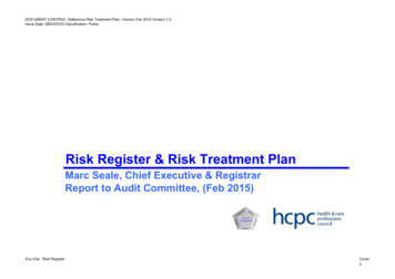
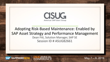
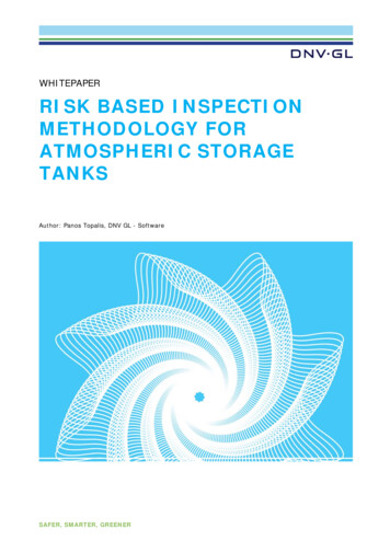
8 in. Sales450 psig6 in. 100 750 psigGPUsPigReceivers8 in.100psig6 in.450psigCompressorSkid2 in. Butane2 in. 100 psig2 in. GlycolNGLStabilizerLPG Storage90,000 galRefrigerationSkidDehydrator100 - 750 psigInlet Gas -4 in.2 in. LPG2 in.LPG Loading2 in. Water2 in. Water3 in. NGLNGL and WaterStorage900 bbl eachFlare2 in. NGLNGL and Water LoadingFig. 2—Block flow diagram.B. Data about the proposed site need to be obtained. Site datashould include a scaled plot plan showing equipment layout(Fig. 1), the physical location of the facility, and basic meteorological data. Average temperature, humidity, and windspeed data obtained from a credible weather service (IowaState University of Science and Technology 2015) can beused in the consequence study. MCEs are defined as a hypothetical explosion, fire, or toxic event that has the potential maximum consequence to the occupants of the building under consideration from among the majorscenarios evaluated. The major scenarios are realistic and havea reasonable probability of occurring considering the chemicals,inventories, equipment, and piping design (Center for Chemical Process Safety 2012). Credible causes of MCEs are typically Rupture of small-bore piping Leak from process equipment Pump/compressor seal failure Gasket failure Loading/unloading hose failure Loss of containment from operational activities suchas filter changing Process upsets such as overfilling of tanksFor this example, the operator assumed that the MCE wouldbe a small-bore line break related to each process step at thefacility. A table was developed (Table 1) that lists the streamor process and the maximum size (equivalent diameter) ofa leak for different MCEs. Typically, MCE tables should bedeveloped by operations, engineering, and safety personnel.The shaded boxes represent the governing or largestrelease for a particular piece of equipment.C. Each of the different MCEs must be modeled to determine theareas of impact. The program “Areal Locations of HazardousAtmospheres” (ALOHA) (EPA 2014) is one program of manyavailable to determine the areal extent of blast, heat, and toxicity effects of the MCEs identified.50Oil and Gas Facilities August 2015The ALOHA model allows the user to enter a single case ata time. The time to run hundreds of cases was reduced greatlyby developing a preprocessor for the program, which allowedthe users to run thousands of ALOHA data sets in a fraction ofthe time usually needed for complex analyses.Blast-pressure models that use the Baker-Strehlow-Tang(Pierorazio et al. 2005) method, as cited in API RP 752 (2009)are used by ALOHA. The ALOHA program uses the BakerStrehlow-Tang blast curves coupled with an air-dispersionmodel for determining the mass of the explosive fuel. Useof air-dispersion
API RP 752 (2009) allows for the evaluation of building loca-tions to use three different assessment approaches: 1.and toxic hydrocarbon sources and occupied structures is a conConsequence-based analysis: This approach generally re-quires that the impacts from maximum credible events (MCEs) be calculated or modeled to determine the impact on a structure. 2.sive forces, fire, or exposure to .