Transcription
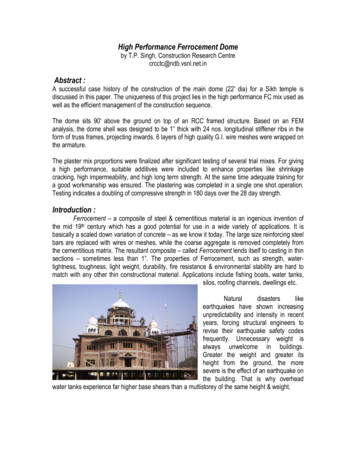
High Performance Ferrocement Domeby T.P. Singh, Construction Research Centrecrcctc@ndb.vsnl.net.inAbstract :A successful case history of the construction of the main dome (22' dia) for a Sikh temple isdiscussed in this paper. The uniqueness of this project lies in the high performance FC mix used aswell as the efficient management of the construction sequence.The dome sits 90' above the ground on top of an RCC framed structure. Based on an FEManalysis, the dome shell was designed to be 1” thick with 24 nos. longitudinal stiffener ribs in theform of truss frames, projecting inwards. 6 layers of high quality G.I. wire meshes were wrapped onthe armature.The plaster mix proportions were finalized after significant testing of several trial mixes. For givinga high performance, suitable additives were included to enhance properties like shrinkagecracking, high impermeability, and high long term strength. At the same time adequate training fora good workmanship was ensured. The plastering was completed in a single one shot operation.Testing indicates a doubling of compressive strength in 180 days over the 28 day strength.Introduction :Ferrocement – a composite of steel & cementitious material is an ingenious invention ofthe mid 19th century which has a good potential for use in a wide variety of applications. It isbasically a scaled down variation of concrete – as we know it today. The large size reinforcing steelbars are replaced with wires or meshes, while the coarse aggregate is removed completely fromthe cementitious matrix. The resultant composite – called Ferrocement lends itself to casting in thinsections – sometimes less than 1”. The properties of Ferrocement, such as strength, watertightness, toughness, light weight, durability, fire resistance & environmental stability are hard tomatch with any other thin constructional material. Applications include fishing boats, water tanks,silos, roofing channels, dwellings etc.Naturaldisasterslikeearthquakes have shown increasingunpredictability and intensity in recentyears, forcing structural engineers torevise their earthquake safety codesfrequently. Unnecessary weight isalways unwelcome in buildings.Greater the weight and greater itsheight from the ground, the moresevere is the effect of an earthquake onthe building. That is why overheadwater tanks experience far higher base shears than a multistorey of the same height & weight.
Gurudwara Brahm Bunga Trust is building a temple in Doraha, Punjab for weeklycongregations. The four storey RCC framed building reaches a height of 70’, above which sits anarchitectural dome of 22’ dia.If built conventionally with brick masonry, this dome along with its base would haveweighed 160 tons. In order to reduce the earthquake damage potential to the building, a need wasfelt to make the dome lighter. A thin shell in Ferrocement was a strong candidate and necessaryanalysis with detailing was carried out. The following paras describe the construction with respectto detailing, materials used, sequence as well as the construction management.Geometry :The dome rises from a 20’ dia circular concrete wall, 6” thick & 4’ high. The top edge of thiswall is a 9” x 9” crest ring beam. The circular wall (also called the dome neck in local lingo) hasreinforcement on both faces. After every 2 ½’ along the circumference, two dowel bars 12” longspring out of the crest beam. These bars would be welded to the rib trusses of the dome.The dome which is nearly 3/5th of a flattened sphere starts with 20’ dia. at the base andbulges outwards to a maximum dia. of 22’. It terminates at a 10’ dia. ring beam, on which sits aconcave, conical finial. The height of the spherical dome between the neck & where the finialstarts, is 12’- 8”. The finial also done in Ferrocement, is 5’ high, topped by a SS spire.Analysis:The dome shell was analyzed on STAAD. The shell was idealized as trapezoidal plateelements, which gradually become smaller in both directions as one moves up. The aspect ratio iskept within 1 : 1.2. The ribs were given the properties of beam elements and were joined to theplates of the outer shell by sharing the same nodes at the junction. The maximum thickness of thearchitectural finishes was to be 3” making a total maximum thick of 4”. To take this dead weight intoaccount, the plate elements were given a thickness of 25mm but a density of 4 times that ofconcrete. The finial load including the spire was distributed equally on all the nodes of the ringbeam.The Analysis showed a maximum hoop tension of 9.5 kg/cm2 near the middle part of theshell, reducing to 1.6 kg/cm2 near the crest.In the orthogonal direction along the longitudes the maximum vertical compressive stresswas 7.6 kg / cm2 near the base reducing as one goes up.The maximum bending moment in the frame rib was .06 T-m at the base (tension insideface) and .04 T-m at the crest (tension outside) with negligible moments in between.Structural Details & Construction :The dome is a 1” thick FC shell stiffened with 24 longitudinal ribs projecting 6” inwards and1” thick. The rib frames are similar to the those in the truss frame method widely used in FC boats.The truss consists of 2 – 8 mm bars connected with zig-zag lattice bars. These curved trusses arenearly 15’ long and follow the profile of the dome. These were fabricated on a simple jig preparedby driving 6 mm dia pins into a level brick floor.The trusses were then erected on the ring beam at the dome base, welding them to thedowels left in the beam for the purpose. At the top, these trusses were, arranged & held in placewith the help of a 10’ dia. pipe ring (broken at one point to allow stringing). This pipe ring wouldlater be embedded in a concrete beam.
The trusses once erected, (like a water melon) were then wrapped around by hoop steel –6mm dia MS bars @ every 3”. The maximum distance between the trusses at the point where thedome is the widest is nearly 3’. In order to reduce this gap, two 8 mm bars run vertically betweeneach pair of trusses, serving as distributionsteel for the hoop bars.The FC dome shell has 6 layers of G.I. square woven meshes embedded, 3 on each sideof the armature. The mesh has ½” square openings and is made from 20 SWG, G.I. wire with aZn coating of 40 – 50 g/m2. G.I meshes normally available in the market are electro galvanizedwith a zinc coating of only 5 – 10 g / m2. Square meshes supposedly resist orthogonal forcesbetter than hexagonal wire nettings. The mesh size was chosen so that the openings are neithertoo big, (to let a pencil back poke through the mesh layers), nor too small so as to act asdelaminating partitions in the cement matrix. Woven meshes can be laid better on a doublecurvatured dome compared to weld meshes.3’ wide meshes were then stretched over the steel armature, such that every area had atleast 3 layers over it. On the inside, the meshes were cut to shape so as to fit between the ribframes. Each rib frame was also covered with 3 layers of wire mesh.The 3 outer and the 3 inner mesh layers were then mutually tied with the help of hairpinshaped GI wire ties. The worker would push the hairpin form the inside & the outer worker wouldtwist & then cut it from the outside using a piano wire cutter. Roughly 2400 of these wire ties wereinstalled.Experience has shown that voids remain after FC application in T junctions, like in ourcase - the junction of stiffener rib to the skin shell. PVC grouting nipples were therefore placed fromoutside @5’ on each truss, to be grouted later. Before the plastering, a thorough checking of thedome shell was carried out ensuring that no part of the mesh was bulging or loose. Extra ties wereinstalled wherever required.Training :One day before the final plastering, the masons were given a ½ day training familiarizingthem with Ferrocement, and with hands on experience on a small bathing tank – specifically madefor the purpose. These masons had no previous experience with Ferrocement. They were taught toconcentrate on proper penetration of the mortar rather than a smooth finish. The masons got achance to try different tools including the small trowel, the wooden float & gloves in difficult areas,
and get a feel of the creamy plaster mix – which was different from the usual harsh one they wereused to.Plastering & Quality Control :The high performance plaster mix used a high content of fly ash, a high dosage of SP aswell as an integral crystal forming waterproofing compound. The sand was a clean washed riversand, sieved below 2mm. A galvanic reaction inhibitor was also added to the mixing water. Theresulting mix was a very creamy, dough like, workable mix.OPC 43 GradeFly AshRiver Sand below 2mmSuper Plasticizer Napthalene basedWaterMix Proportions11.5By Volume2.51.2 % of OPC37 ltrs. / bag of cementOn the plastering day, the necessary steps for QC were enforced. Exact measures in theform of boxes / buckets / liter measures etc. for the ingredients were organized. In order tomaintain the consistency of the mortar over different batches a flow table was kept in shade closeto the mixer. A small sample of the mortar was filled in the cup placed on the flow table. After liftingoff the cup, a blow count of the flow table gave the measure of consistency. The blow countremained between 13 & 14, owing to the rigorously trained workforce and a strict control over theingredients including water.6” cubes were filled from 2 batches and placed next to the dome wall on the inside afterdemoulding, in order to receive the same curing as the in-situ material. After a months’ curing,each of the cubes was sliced into eight smaller cubes for later age testing. Since an HVFA mix hadbeen used, strengths were monitored for over a year showing a phenomenal gain in strength overtime. The results are as per table below :Age in Days3090180Cube Compressive Strength (kg/cm2)356563715Suitable work platforms at 3 levels along the 13’ height of the dome both inside & outsidewere erected. A small bridge to convey the plaster mix to the dome interior from over the top ringwas also erected to avoid any disturbance to the dome skeleton by worker movement.The plastering day began at 6.30 am with the first plaster load reaching the dome by 7.00am. Eighteen masons – nine outside & nine inside, worked for 11 hrs with 2 tea breaks & a lunchbreak in between to finish the plastering in a one shot operation. The cycle time on each one bagmix, which depended on how fast the masons could use up the material, was 20 – 25 minutes. Awater mist spray was kept ready to avoid drying out from the sun and the wind, but was used little.Work proceeded smoothly from bottom up towards the top. Each pair of masons working inside &outside ensured that the mix penetrated both ways to create a monolithic layer 25 mm thick.3 hours after the plaster application started, one pair of masons started putting on 2 – 3mm thick finished coat with the same plaster mix ensuring that no mesh was left exposed.
Durability Assessment :Since cementitious materials with embedded steel usually deteriorate due to ingress ofatmospheric elements into the matrix through its numerous pores and micro cracks, any reductionin porosity and micro cracking potential is seen as longer durability.The Chloride ion permeability as per ASTM 1202 was checked on 28 day cured specimensand found to be superior to ordinary cement mortar without fly ash of the same consistency. Longterm testing could not be carried out due to unavailability of more samples. However, previoustesting of HVFAC has shown a multifold improvement in permeability with age. This indicates thatthe Ferrocement mix used on this project will be much more impermeable and hence durablecompared to conventional Ferrocement mixes. The increased compressive strength at long termages ( table above ) supports this hypothesis. The mechanism that makes this possible is :The high volume of pozzolona (fly ash) in the mix participates in a secondary reaction withCa(OH)2 – a byproduct of the cement hydration. This secondary pozzolonic reaction continues forseveral months, and the reaction products keep filling the pores in the cementitious matrix makingthe final product much more dense and impermeable. This consequently improves the propertieslike strength, durability, elastic modulus and reduces the corrosion potential of steel inside. Thelower cement content in such a mix further contributes to a durable matrix by virtue of reducedshrinkage and reduced heat of hydration. This in turns reduces the risk of micro cracking therebyensuring that detrimental elements do not find pathways into the cementitious matrix. Hence thehigh performance of this mix.Curing & Post Treatment :The day after plastering, an elaborate curing system was set up. The dome was wrappedwith jute sacks, further covered with a plastic sheet tied all over. A rubber hose with tiny holes init & connected to a 500 liter water tank, ran along the circular crest keeping the sacks continuouslywet. This was kept in place for a month. The inside was sprayed liberally several times a day with apressure hose.12 days later, the crest beam at the dome top was cast along with a 2” thick arched slabwith 6 radial ribs to take the load of the metal spire.
After 30 days the interior was plastered with a polymer modified cement plaster to serve asa weathering protection to the Ferrocement shell. 3 days following the plaster, grouting of thenipples left in the shell earlier was carried out. A hand operated Killick Nixon pump along with apolymer modified cement – Fly ash slurry was used for grouting. Nearly four cement bags wereused in the grouting, revealing that inspite of the extraordinary workmanship and the extraworkable mortar mix, a great number of voids are left inevitably in Ferrocement construction of thistype.The Finial:The conical finial cap is also a hollow shell sitting on the 10’ dia. crest beam at the top ofthe dome.This concave conical shell was created
resulting mix was a very creamy, dough like, workable mix. Mix Proportions OPC 43 Grade 1 Fly Ash 1.5 By Volume River Sand below 2mm 2.5 Super Plasticizer Napthalene based 1.2 % of OPC Water 37 ltrs. / bag of cement On the plastering day, the necessary steps for QC were enforced. Exact measures in the