Transcription
STANDARD DESIGNAIR FORCEPERMANENT PARTY ENLISTEDDORMITORY
JANUARY 2019TABLE OF CONTENTSChapter 1 Introduction1.1 Standard Design1.2 Air Force Standard Design Policy1.2.A Required use of Standard Designs1.2.B Integration with Air Force Corporate and Installation Facility Standards1.3 Applicability1.3.A. Additions and AlterationsChapter 2 Facility Design2.1 Facility Description2.1.A Function2.1.B Typical Users2.1.C Related AFMAN 32-1084 Category Code2.2 Criteria2.2.A Sustainability2.2.B Security and Antiterrorism2.3 Notional Site2.3.A Site Location, Orientation and Adjacencies2.3.B Parking2.3.C Vehicular and Pedestrian Circulation2.3.D Notional Site Plan2.4 Building Design2.4.A General Considerations2.4.B Building Configuration2.4.C Interior/Exterior Relationships2.4.D Functional Area Requirements2.4.E Circulation concept Diagram Community Space2.4.F Visual Connection Diagram for Community Space Module2.4.G Room Data Sheets2.4.H Interactive Programming Worksheet1
JANUARY 2019CHAPTER 1 INTRODUCTION1.1. STANDARD DESIGNStandard Designs provide functional and spatial requirements for specific Air Forcefacility types and are intended for use in conjunction with DoD Unified Facilities Criteria(UFC), Air Force Corporate Facility Standards, Installation Facility Standards, and otherapplicable standards.Standard Designs are living documents that are periodically reviewed, updated, andmade available to users by posting on the Whole Building Design Guide. This StandardDesign, as well as those for many other Air Force facilities, can be accessed at this website: esignsThis Standard Design is effective upon issuance and is distributed only in electronicmedia.1.2 AIR FORCE STANDARD DESIGN POLICY1.2.A. Required use of Standard DesignsThe use of Air Force Corporate Facilities Standards (AFCFS), Installation FacilityStandards (IFS) and Standard Designs has been codified in the most recent version ofAFI 32-1023, Designing and Constructing Military Construction Projects (ref (c)). Incompliance with the AFI, all facility designs must conform to the standards outlined andspecified in the AFCFS, and if there is an applicable Installation Facilities Standards(IFS) document, the project must conform to those standards as well.This Standard Design was developed in close coordination with the facility’s functionalusers to by determine personnel counts, allowable/authorized space/room sizes,adjacency diagrams between the functional spaces and the overall facility spacerequirements. It also addresses special requirements unique to this facility type. Usethis Standard Design in conjunction with other AF policy and regulations such as, AFI’s,and UFC’s when programming and designing this facility type.1.2.B. Integration with Air Force Corporate and Installation FacilityStandardsThe Air Force Corporate Facilities Standards (AFCFS), is an enterprise-wide program offacility standards establishing an acceptable level of quality and performance for facilitydesign, facility operations and ongoing building maintenance. The AFCFS provides anexciting direction forward; intended to create sustainable installations and cohesive,efficient, High Performance and Sustainable Buildings throughout the Air Force.Installation Facilities Standards (IFS) are part of the Air Force Corporate FacilitiesStandards (AFCFS) program to assist bases in implementing facilities standards at thelocal level. Bases develop and maintain an IFS, which replaces the ArchitecturalCompatibility Plan, as a component plan of the Installation Development Plan (IDP).2
JANUARY 2019Programmers and designers for Permanent Party Enlisted Dormitory must use thisStandard Design to ensure the specific functional, spatial, and special requirementsare met, meet the local requirements established by the IFS, and the overall Air Forcerequirements set forth in the AFCFS.1.3 APPLICABILITYThis Standard Design provides requirements for evaluating, planning, programming,and designing a 144-person Permanent Party Enlisted Dormitory that supports themission, is appropriately sized, flexible, durable, and life-cycle cost efficient. Theinformation in this Standard Design applies to the design of all new constructionprojects, to include additions, alterations, and renovation projects worldwide. It alsoapplies to the procurement of Design Build services for the above-noted projects.Alteration and renovation projects should update existing facilities to meet the guidanceand criteria within budgetary constraints.The facility size is dependent on the of persons assigned to the dormitory. ThisStandard Design is based on 144 persons, which is a typical requirement for many AirForce Permanent Party Enlisted Dormitories. Use the Interactive ProgrammingWorksheet to adjust the overall gross building area based on the number Airmen to behoused.CHAPTER 2 FACILITY DESIGN2.1 FACILITY DESCRIPTION2.1.A. FunctionThe primary function of the Permanent Party Enlisted Dormitory is to provide a facilitythat fully supports the mission with a flexible state-of-the-art building. The facilitysupports 144 single-person Dormitory Rooms within a standalone three-story facility.The facility is comprised of the following modules: First Floor Common Area Module,Second Floor Common Area Module, Third Floor Common Area Module and DormitoryRoom Modules. The Modules are further broken down into rooms/spaces as follows(included rooms/spaces are noted below module title):Area ModulesA – First Floor Common Area ModuleEntry VestibuleCommunity Activity SpacePassive Activity SpaceKitchenOffice/Storage/Closet3
JANUARY 2019Unisex ToiletBuilding Utility Rooms (MEP, Communications, etc.)Vertical Circulation (Elevator and stairs)B – Second Floor Common Area ModuleActivity SpaceFitness CenterBuilding Utility Room (Electrical)Vertical Circulation (Elevator and stairs)Laundry RoomC – Third Floor Common Area ModuleActivity SpaceTheater/Meeting RoomBuilding Utility Room (Electrical)Vertical Circulation (Elevator and stairs)D – Dormitory nical Chase2.1.B. Typical UsersThis Dormitory is used by Air Force Permanent Party Enlisted Personnel.Hours of operation for this facility type are 24-7 and this Standard Design is for 144Dormitory Rooms.2.1.C. Related AFMAN 32-1084 Category CodeThe related AFMAN 32-1084 Category Codes are as follows: This facility would begoverned by Chapter 7 Housing and Community, Category Group 72 UnaccompaniedPersonnel Housing (UPH).2.1.D. AFCFS4
JANUARY 2019Consult the Air Force Corporate Facilities Standards (AFCFS) to determine qualitystandards for this facility group. This Standard Design is considered a Group 2Dormitory hierarchy.2.2 CRITERIAAPPLICABLE UNIFIED FACILITY CRITERIAComply with UFC 1-200-01, DoD Building Code (General Building Requirements). UFC1-200-01 provides applicability of model building codes and government unique criteriafor typical design disciplines and building systems, as well as for accessibility,antiterrorism, security, high performance and sustainability requirements, and safety.Use this Standard Design in addition to UFC 1-200-01 and the UFCs and governmentcriteria referenced therein. UFC 1-200-01 references other “Core UFCs” that areapplicable to this Standard Design as well as most all DoD facilities.Meet the requirements of UFC 1-200-02 and achieve green building certification inaccordance with the current AF Sustainable Design and Development memo. Most, butnot necessarily all applicable Unified Facility Criteria documents are listed below:UFC 1-200-01DoD Building Code (General Building Requirements)UFC 1-200-02High Performance and Sustainability Building RequirementsUFC 1-300-07ADesign Build Technical RequirementsUFC 3-101-01ArchitectureUFC 3-110-03RoofingUFC 3-120-01Design: Sign StandardsUFC 3-120-10Interior DesignUFC 3-190-06Protective Coatings and PaintsUFC 3-201-01Civil EngineeringUFC 3-201-02Landscape ArchitectureUFC 3-210-10Low Impact DevelopmentUFC 3-220-01Geotechnical EngineeringUFC 3-230-01Water Storage and DistributionUFC 3-240-01Wastewater CollectionUFC 3-250-01Pavement Design for Roads and Parking AreasUFC 3-250-03Standard Practice Manual for Flexible Pavements5
JANUARY 2019UFC 3-250-04Standard Practice for Concrete PavementsUFC 3-301-01Design: Structural EngineeringUFC 3-400-02Design: Engineering Weather DataUFC 3-401-01Mechanical EngineeringUFC 3-410-01Heating, Ventilation, and Air Conditioning SystemsUFC 3-410-02Lonworks Direct Digital Control for HVAC and Other LocalBuilding SystemsUFC 3-420-01Plumbing SystemsUFC 3-450-01Noise and Vibration ControlUFC 3-501-01Electrical EngineeringUFC 3-520-01Interior Electrical Systems,UFC 3-530-01Design: Interior and Exterior Lighting and Controls,UFC 3-550-01Exterior Electrical Power DistributionUFC 3-570-01Cathodic ProtectionUFC 3-575-01Lightning and Static Electricity Protection SystemsUFC 3-580-01Telecommunications Building Cabling Systems Planning andDesignUFC 3-600-01Fire Protection Engineering for FacilitiesUFC 4-010-01DoD Minimum Antiterrorism Standards for BuildingsUFC 4-020-01Security Engineering Facilities Planning ManualUFC 4-021-01Design and O&M: Mass Notification SystemsUFC 4-010-06Cybersecurity of Facility-Related Control Systems2.2.A. SustainabilityComply with the Federal sustainability requirements as detailed in UFC 1-200-02, HighPerformance and Sustainable Building Requirements. Determine third-partycertification requirements based on Table 1-1 of UFC 1-200-02 and current AFguidance at https://www.wbdg.org/ffc/af-afcec.2.2.B. Security and Antiterrorism6
JANUARY 2019The facility must meet the requirements UFC 4-020-01 Security Engineering FacilitiesPlanning Manual, UFC 04-010-01 DoD Minimum Antiterrorism Standards for Buildings.2.3 NOTIONAL SITE2.3.A. Site Location, Orientation and AdjacenciesThe notional site plan diagram demonstrates key site development criteria. It is not asite-specific solution. The information represents the land requirements to constructthis facility and includes associated AT standoff and parking. Additional land may beneeded to comply with the stormwater management requirements of UFC 3-210-10Low Impact Development. Utilization of existing or shared parking is allowable andmay reduce the total acreage required for the facility. Adapt the requirements to thespecific site and location and comply with the applicable Installation Development Plan(IDP) and Area Development Plan (ADP) for facility siting.Several factors determine the most appropriate and cost-effective location for a facility.The availability and capacity of required utilities and the mass/scale of the facilityrelative to adjacent structures and noise issues must be analyzed.Emphasis must be placed on operation, function, and safety when siting the facility.The preferred location of the facility is determined by the base master plan and isgenerally located in a specific geographic area or “zone” of the base.The approximate project area required for the facility is 7.00 acres, which includesantiterrorism/force protection standoff and parking.2.3.B. ParkingParking must be provided to accommodate 70% of the design capacity of the facility.2.3.C. Vehicular and Pedestrian CirculationConvenient and safe vehicular access and circulation must be provided for personalvehicles and essential services, including operations, maintenance, deliveries, dumpster/recycling collection, and emergency services.Locate sidewalk networks to provide convenient and safe pedestrian circulation fromexisting circulation elements of the project site to the new parking areas and doors ofthe facility. Sidewalk width must accommodate maintenance and emergency servicesrequirements.7
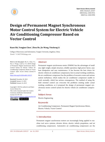
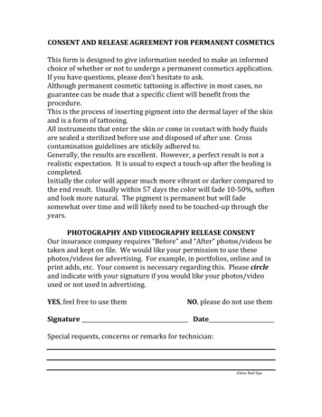
JANUARY 20192.3.D. Notional Site Plan8
JANUARY 20192.4 BUILDING DESIGN2.4.A. General ConsiderationsGeneral considerations of the facility design are centered on: The Dormitory Modules and Common Area Modules.The functional relationships between the modules as well as between the spaceswithin the modulesThe general personnel flow requirements within the facility and Common Areasuch that there is interaction among the enlisted personnel occupying the facility.Residents and visitors enter the facility through the First Floor Common Area Moduleand as well as through First Floor Dormitory Module corridor ends.The Building Support areas within the First Floor Common Area Module need exterioraccess.Other general considerations include: The size of the Permanent Party Enlisted Dormitory shall be affected by thenumber of Dormitory Rooms.2.4.B. Building ConfigurationThe building should be configured for future expansion or reconfiguration. The generalsize of the building is based on the number of dormitory rooms required. The generalvariation of configurations of the dormitory is a T-shape, L-shape and H-shape. The sizeof the facility is affected by the number of Dormitory Modules.2.4.C. Interior/Exterior RelationshipsThe dormitory will have access to POV and Visitor parking as well as outdoor areasaround the dormitory wings.2.4.D. Functional Area RequirementsFacility Modules Adjacency Diagrams & Conceptual Axonometric Layout(s)The composite diagram(s) represent ways to conceptually assemble the functionalareas (modules) into a cohesive whole. Individual modules are represented bydifferent colors.Spaces and rooms that are integrally related with a specific functional connection oroperational flow are grouped into a module. Modules and the associated room datasheets identify specific criteria and additional detail for each functional area of thefacility as outlined in the Interactive Programming Sheet located at the end of thedocument.The modules are a grouping of functional spaces and represent “Lego blocks” to beused in a “kit-of-parts” design approach. Use the fixed modules as pre-assembled9
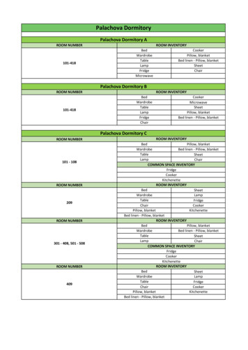
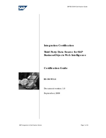
JANUARY 2019pieces of the facility “puzzle”. Assemble them to comply with the required adjacenciesindicated in the diagrams and module plans.Modules must be used as shown in this Standard Design to the greatest extent possibleand must not be deconstructed or altered except as indicated herein. The intent of theStandard Design criteria is to avoid manipulation of the composition, functionalrelationships, adjacencies, and module sizes. Modules contain fixed attributes andmust not be changed arbitrarily. Modules may be rotated, flipped, and/or mirrored toaccommodate an overall composition or site issue, but this must not be done arbitrarilyand should occur only when necessary. One exception is the Primary Building Entry(see 2.3.D Notional Site Plan) to Common Area Module. The Main Entry should becustomized based on solar orientation, local architectural context, and other site-specificissues.Some modules are linked to space requirements that increase or decrease in sizebased on the number of dormitory rooms. In these cases, increase or decrease the sizeof the Common Area Modules to match the revised scope calculation. This maysometimes require minor adjustments in other adjacent modules so that they properly fittogether to create a constructible facility floor plan. Spaces must comply with anycritical dimensions indicated on module plans. Manipulate as few modules as possibleto create a constructible facility. The resulting composite plan must respect theestablished modules adjacencies and must not exceed the authorized project scope.Functional Adjacency DiagramThe following Functional Adjacency Diagrams form the basis of design for thePermanent Party Enlisted Dormitory Standard Design. The Standard Design is basedon a three-story 144-person dormitory. The facility is programed around the DormitoryModules which are in wings branching off the centrally located Commons AreaModules.10
JANUARY 20192.4.E. Circulation Concept Diagram Community SpaceThe Circulation Concept Diagram shows the concept behind the facility composition. Thecirculation pattern is meant to be along the arrow axis at the edges of the Community Space tomaximize functionality of the open space and maximize circulation exposure to the open space.The Front Façade of the facility is meant to be customized per project according to siteconditions, local architectural context, solar orientation, or Installation specific missions.11
JANUARY 201912
JANUARY 201913
JANUARY 201914
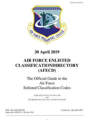
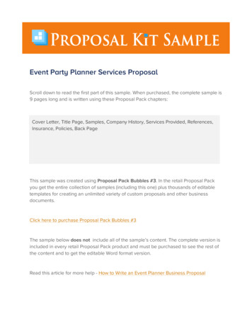
JANUARY 20192.4.F. Visual Connection Diagram for Community Space ModuleThe Visual Connection Diagram for Community Space Module shows the conceptbehind the hierarchy of spaces within the Community Space. The intention is toincrease dynamism in the space via visual connection between active areas. That is,users of the Laundry Room can see the users of the common space and vice versa.The general principle is to create clear visual connections between the main entry, theFitness Center, the Laundry Room, and the Community Spaces.15
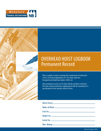
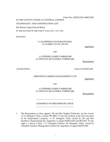
JANUARY 2019MODULE A – First Floor Common Area ModuleModule Net Area: 5125 sq.ft. Function and AdjacencyModule A consists of the Entry Vestibule, Activity Spaces, Kitchen, Office/ StorageCloset, Uni-Sex Toilet, Building Utility Rooms (MPE) and Vertical Circulation (Elevatorand Stairs). This Module is connected to the First Floor Dormitory Module.The Entry Vestibule functionality includes creating making the facility distinct by relatingto local architecture, orienting to local site conditions including solar orientation. TheModule A Entry Vestibule along with exterior curtain wall configuration shown on plan isconceptual in nature.16
JANUARY 201917
JANUARY 201918
JANUARY 2019MODULE B – Second Floor Common Area ModuleModule Net Area: 2567 sq.ftFunction and AdjacencyModule B consists of Activity Spaces, Fitness Center, Laundry Room, Building UtilityRoom (Electrical), and Vertical Circulation (Elevator and Stairs). This Module isconnected to the Second Floor Dormitory Module wings.19
JANUARY 201920
JANUARY 201921
JANUARY 2019MODULE C – Third Floor Commons Area ModuleModule Net Area: 2424 sq.ftFunction and AdjacencyModule C consists of Activity Spaces, Theater/Meeting Room, Building Utility Room(Electrical), and Vertical Circulation (Elevator and Stairs). This Module is connected tothe Third Floor Dormitory Module wings.22
JANUARY 201923
JANUARY 201924
JANUARY 2019MODULE D – Dormitory ModuleModule Net Area: 704 sq. ft. total or 352 sq. ft. per dormitory roomFunction and AdjacencyModule D consists of the two Single-Person Dormitory Rooms. The Modules areattached to a central double-loaded corridor which forms the Dormitory wings of thefacility. The Dormitory Rooms consist of a Bedroom area, Entry/Kitchenette/Closet andBathroom. The Dormitory wings connect to the centrally located Common AreaModules. Each Dormitory wing will have a stair at the end of the double-loaded corridorfor egress. Dormitory wing separated from Common Areas with a pair of oppositeswinging fire rated doors. The Dormitory Module has a shared vertical MechanicalChase.25
JANUARY 201926
JANUARY 201927
JANUARY 201928
JANUARY 20192.4.G. Room Data SheetsSpecific requirements for each room, space, or area are provided on room data sheetsthat correspond to their respective color-coded Modules, basis of design FunctionalAdjacency Diagram as well as the Interactive Programming Worksheet. Informationcontained on the data sheets defines the functional and physical requirements foreach of the spaces within the facility type and are generally minimum requirements.29
JANUARY 2019MODULE A – FIRST FLOOR COMMON AREA - ENTRY VESTIBULEINDEXA1Description/UsageMain entrance vestibule.Ceiling Height30’-0” minimumWindowsCurtain wall, insulated meeting UFC 4-010-01DoorsFinishesTypeSecurity/HardwareAluminum storefront entry doors, pair 3'-7', wide styleView Panels/Kick PlatesFull glassWallsGypsum board – painted or exposed masonry or curtain wallFloorCeramic tile, quartz epoxy, finishe
The Air Force Corporate Facilities Standards (AFCFS), is an enterprise-wide program of facility standards establishing an acceptable level of quality and performance for facility design, facility operations and ongoing building maintenance. The AFCFS provides an exciting direction forward; i