Transcription
58TH ANNUAL FUZE CONFERENCE58th Annual Fuze ConferenceJuly 7 – 9, 2015A Synchronous AddressedCommunications Method forCoordinating Multiple Outputsand Effects in Fuzing SystemsAuthor:Steven P. CornettPresented by: Steven P. CornettE NG AG E . E NA BL E .1 2010 Excelitas TechnologiesE XCE L .1
58TH ANNUAL FUZE CONFERENCEAbstract and Problem Statement Problem Definition-Selectable yield warheads require multiple effectsMultiple Effects useful in Multiple-layer penetration weaponsRobust and simple means to set multiple firing modules are required Reduces manufacturing costs Lowers number of conductors of cables & size of connectors Excelitas proposes a multi-drop network system to set multiple effects This presentation will cover-2The elements used in the proposed communication interfaceAn explanation of how the elements interactThe work to date on the development of the interfaceThe path forward toward interface development2
58TH ANNUAL FUZE CONFERENCEDeveloping a Solution Motivation for the effort--Originally motivated in response to NAC (National Armaments Consortium) researchtopic FUZ-15-27 Requested development of low voltage power and communication protocols forselectable yield, multi-mode, and multi-purpose warheadsThe solution needs to be compliant with Fuze industry standards MIL-STD-1901A for Ignition Safety Devices (ISD) MIL-STD-1316 for Electronic Safe and Arm Devices (ESAD) The proposed system integrates commercially available networking systemswith a robust 4-wire networking system-The solution should allow the operation of an internal data busShould also have a Electronic Module (EM) to multiple Firing Module (FM) interfacethat will be robust in a missile environment Selected ARINC-429 physical layer interface ARINC (Aeronautical Radio Incorporated) Tutorial from Avionics Interface 354/ARINC429 Tutorial.pdf33
58TH ANNUAL FUZE CONFERENCEI2C as the FM Internal Bus The I2C (Inter-Integrated Bus) is a multiple-master, multiple-slavebus introduced by Philips (now NXP) in 1982-Originally developed to allow microprocessor control of electronicsthrough slave peripheral devicesWidely adopted as a standard by the electronics industry I2C is used in a wide variety of peripheral components useful tothe defense industry-4Digital PotentiometerNon-volatile Memory (EEPROM, Flash, etc.)Data acquisition Analog to Digital Converter (A/D)Digital to Analog Converter (D/A)Temperature SensorsDigital Output AccelerometerPort Extension4
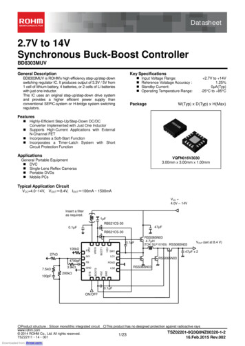
58TH ANNUAL FUZE CONFERENCEExample of I2C use in Fuzing 3.3V 3.3VTP98 3.3VTP9912345SCLSDAEEPROM GER DELAY TIMER10VCCSCLSDAA1A0SHDN 3.3V 3.3V 3.3VRHRWRL987GND6ISL22316TP1003TP10254 6 V REF VOUT-12 V-Resistance 10k OhmFrom Trigger LatchLATCHED TRIGGER I2C Components used in Fuzing-5Digital Potentiometer Calibration Analog Timer (as above)Data Acquisition Time, temperature, accelerationMux and SwitchesNon-volatile Memory5
58TH ANNUAL FUZE CONFERENCESerial Peripheral Interface SPI (Serial Peripheral Interface) is a synchronous full-duplex bus developedby Motorola Semiconductor (now spun off as Freescale)-Data is exchanged through a circular bufferDe facto standard available on microcontrollers and programmable logic Bus is designed to have one master and one slave per control line-6Used for External Memory and LCD I/OCommon interface for Data Acquisition components (A/D, D/A)6
58TH ANNUAL FUZE CONFERENCEARINC 429 Data Bus Between Modules ARINC-429 is a combination of a two-wirefull-duplex physical layer and communicationprotocol Physical layer consists of one line transmitterand one or more receivers 100KHz bit rate proposed-Four bit separation between data framesTri-state signal combining signal and clockClock integrated through 50% duty cyclebetween data and ground stateARINC 429 Protocol Tutorial. Avionics Interface Technologies, pp. 10-1177
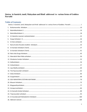
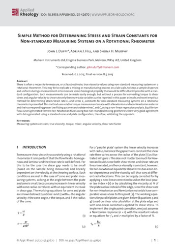
58TH ANNUAL FUZE CONFERENCEPhysical Layer Simulation with LTSpiceData / Clock Pattern GenerationLine DriverLine Receiver First Step was an electrical simulation of a single line driver and receiver-Simulation performed using LTSpice Models from Linear Technology and Texas Instruments Return impedance simulated by separation of 2Ω between driver and receiverLTSpice is a trademark of Linear Technologies Corp., Reg U.S. Pat & TM Office88
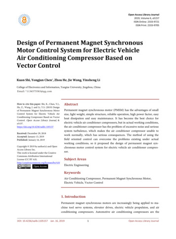
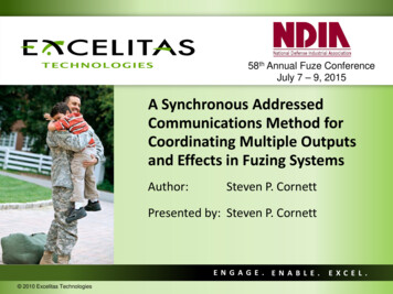
58TH ANNUAL FUZE CONFERENCELine Driver and Receiver Simulation PlotInput Serial DataInput Serial ClockReceiver One StateReceiver Zero State Line Driver and Receiver Transient Plot-9Signal in Yellow is Output of Differential Amplifier U4Digital state outputs from comparators U7 & U8 using signal from U49
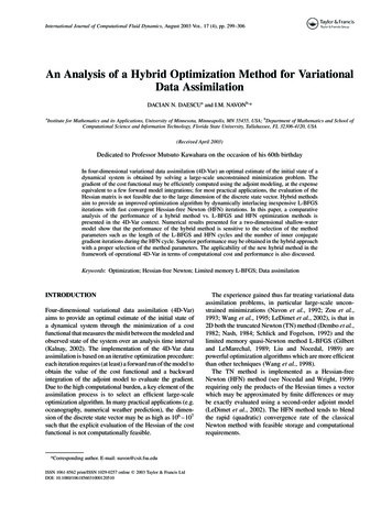
58TH ANNUAL FUZE CONFERENCENetwork Structure Prototype Network Structure--10TransmitterMaster Electronic ModuleFull-Duplex four-wire structure between(MEM)Electronic Module and Firing Modules Physically connected with shielded twisted paircable Separate pair for transmission and receivingFM 1 RXchannelMEM – Master Electronic Module Originates Communications requestsFM 2 RXUp to n Firing Modules (FM) Respond to requests “Speak only when spoken to” Only one FM Line driver activeFM n-1 RXMEM TxReceiving FiringModule (FM1)Receiving FiringModule (FM2)Receiving FiringModule (FMn-1) All others in High impedance output modeFM address handling through a protocol handlerPrototyped with programmable logicASIC envisioned for production useReceiving FiringModule (FMn)FM n RX10
58TH ANNUAL FUZE CONFERENCENetwork Frame Characteristics The data frame shall be 32 bits long The general elements of the frame consists of:-11FM Address Eight bits (255 FMs and Electronic Module)Write or Read 0 for Write, 1 for readFrame data – 16 bit lengthFrames in transaction (1 to 8)First Frame (OF) and End Frame (EF) bits Beginning and ending of a transactionParity bit Insures that that number of 1s transmitted is an odd number Bit set or cleared to obtain count11
58TH ANNUAL FUZE CONFERENCEComponent Selection Initial proof of concept will incorporate elements of the FM Mockup-Digital Potentiometer to simulate Analog TimerDigital Switch to handle timing range selection Initial proof of concept of FM protocol handler performed with a Kinetis microcontroller board-Standard Arduino R3 form factor for expansion board designSingle SPI and I2C ports on board target device Off the shelf Line Driver and Receiver (Holt Integrated Circuits HI-8592)Kinetis is a trademark of Freescale Semiconductor, Inc., Reg U.S. Pat & TM Office1212
58TH ANNUAL FUZE CONFERENCEThe Path Forward Design Validation of Proof of Concept-Will modify a small ESAD design to prototype MEM and FM modules ESAD successfully tested in high acceleration missions Design will prove and “dial in” network use in n-FM system-Examine reliability of strict Bus Drop versus Star Topology Network part of larger effort in multi-effects Fuze system development-Contact transmission, Charging, and Low Voltage Power Supply Goal of a cost-effective, highly manufacturable multi-effects FuzeARINC 429 Protocol Tutorial. Avionics Interface Technologies, pp. 61313
58TH ANNUAL FUZE CONFERENCEExcelitas Technologies, Advanced Electronics SystemsSteven P. Cornett Electrical Engineer, Energetic Systems (937) 865-6154 steven.cornett@excelitas.comAl Starner Programs Leader, Energetic Systems (937) 865-3544 Allen.Starner@excelitas.com14Dr. Glen Kading Electrical Design Leader, Energetic Systems (937) 232-7375 Glen.kading@excelitas.comRoy Streetz Vice President, Energetic and Power Systems (937) 353-2242 Roy.Streetz@excelitas.com14
58TH ANNUAL FUZE CONFERENCEENGAGE. ENABLE. EXCEL.1515
ARINC 429 Protocol Tutorial. Avionics Interface Technologies, pp. 10-11 . 8 8 58 TH A NNUAL F UZE C ONFERENCE Physical Layer Simulation with LTSpice First Step was an electrical simulation of a single line driver and receiver -Simulation performed using LTSpice -Models from Linear Technology and Texas Instruments Return impedance simulated by separation of 2Ω between driver and .