Transcription
Chiller ControllerError / AlarmManualVersion: 09-20-2013
TABLE OF CONTENTSError Codes with Causes and Solutions: Microproccessor Features. Page 1 Water Temperature Sensor Error. Page 2 Compressor Pressure Sensor Error. Page 3 Refrigerant High Pressure Error -H I I . Page 4 Refrigerant Low Pressure Error -L 0 I . Page 5 High Water Temperature Alarm . Page 6 Low Water Temperature Alarm . Page 7 Low Water Flow Alarm . Page 8 Location of Fuses, Contactors and Overload Relays . Page 9 Micro Processor Operation, Programming and Settings . Pages 9-14 Drake Warranty . Page 15 Micro Processor Diagram . Page 16 PSG Micro Control Board - Wiring Locations . Page 17
MICROPROCESSORFEATURESControl power on/offIndicator light displayL.E.D. displaySystem pump power on/off switchScrolling up & down buttonsStandard Features Control operates to a /- 1 F accuracyPowered from the chiller 24 volt control circuit. No high voltage interference.1 or 2 compressor control capabilityOperates and displays in F and CControls chiller on inlet or outlet temperatureScroll through set up and review mode30-second compressor time delay to prevent short cycling and nuisance faults60-second hot gas solenoid delay to prevent false hot gas feeding duringcompressor start up Lock out relay shuts down the chiller when control fault settings activate Automatic compressor lead lag on dual circuit chillers Weather resistant for outdoor use Basic chiller functionality for ease of set up and operation Factory configured for job site operation Factory default function code to reset the controller to the initial factory settings Two L.E.D. display windowsa) Inlet and outlet temperature during chiller operationb) Displays refrigerant high and low pressure in review mode1) No cap tubes to break causing a loss of refrigerant and down time2) No refrigerant revcovery to change out the pressure transducer Indicator lightsa) Chiller control power on/off switch with green indicatorb) System pump on/off switch with green indicatorc) Compressor run indicator lightsd) High and low refrigerant pressure red fault indicatore) Low fluid flow red indicator Display flashes all chiller safety faultsa) High fluid temperature outlet alarmDisplay only - does not shut the chiller downb) Low fluid temperature outlet alarmShuts down the chiller and requires manual resetc) High refrigerant pressureShuts down the chiller and requires manual resetd) Low refrigerant pressureShuts down the chiller and requires manual resete) Low water flow through evaporatorShuts down the chiller and automatically resets when flow is restored Monitors and logs compressor run hours1.
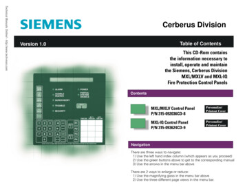
1.Outlet or InletWater TemperatureSensor ErrorIf the temperature sensor transmits an out of range temperature it will be perceived as bad. “Err” will beginflashing in the upper numeric LED while one of the following will be displayed on the bottom numeric LED:“tSi” for the inlet temperature sensor, and “tSo” for the outlet temperature sensor. The control will de-energizethe compressors and hot gas valves and the alarm relay will energize. The re-circulation pump remains energized.The fault is cleared by momentarily pressing the “Power” button on the microprocessor after the error has beenresolved. The fault is not cleared by turning off and on the power disconnect switch. (Power disconnect breaker)Possible Cause:1) Terminal plug is not securely fastenedto the controller board2) Loose wire on the terminal plug3) Defective sensor1Solution: (with the disconnect off)1) Secure the terminal plug to thecontroller board2) Push the loose wire into the terminal plug3) Replace the sensorA) Inlet sensor Drake part number D80-303B) Outlet sensor Drake part number D80-3044) Replace the Microprocessor Drake partnumber D80-3442
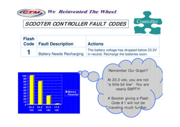
2.CompressorPressureSensor ErrorIf the voltage received from the pressure sensor’s) is .4vdc or 4.6vdc the pressure sensor will be perceivedas bad since it’s normal operating parameters are .5vdc to 4.5vdc. “Err” will begin flashing in the upper numeric LEDwhile one of the following will be displayed on the bottom numeric LED: “tL1” for compressor 1 low pressure sensor,“tL2” for compressor 2 low pressure sensor, “tH1” for compressor 1 high pressure sensor, and “tH2” for compressor2 high pressure sensor. The compressor and hot gas valve will be de-energized and the alarm relay will energize. Thefault is cleared by momentarily pressing the “Power” button on the microprocessor after the error has been resolved.The fault is not cleared by turning off and on the power disconnect switch. (Power disconnect breaker)Possible Cause:1) Transducer harness plug is not securely fastened to the transducer body2) Loose cable wire on the terminal block of the controller3) Voltage to the Chiller is too low / too high4) Defective transducer25) Defective cable harness6) Defective microprocessorSolution: (with the disconnect off)1) Secure the cable harness plug to the transducer2) Tighten the loose wire into the terminal plug3) Check the line voltage and the transformersecondary and correct if necessaryA) Line voltage should be 208-230V /- 10% If out ofrange this will effect transformer output.B) Control circuit transformer output should be 24V /- 10%(See page 8 for location) Drake part number D59-1984) ReplaceA) HP transducer Drake part number D80-275B) LP transducer Drake part number D80-2765) Replace the Cable harness Drake part number D59-3696) Replace the microprocessor Drake part number D80-3443.
3.RefrigerantHigh PressureErrorIf the outlet pressure exceeds the high pressure set point the “Hi Pres” led will illuminate and the “Hi Pres”alarm parameter name will begin flashing in the upper numeric LED. The compressor and hot gas valve will bede-energized and the alarm relay will energize. The parameter value will be displayed in the lower numeric LED.The fault is cleared by momentarily pressing the “Power” button on the microprocessor after the error has beenresolved. The fault is not cleared by turning off and on the power disconnect switch. (Power disconnect breaker)Possible Cause:1) Blocked or dirty condenser coil2) Defective fan motor3) Poor installation location (overhang, other equipmentinstalled too close, Wall, fence or other object is within 3’of the chiller blocking air flow4) Refrigerant overcharge5) Microprocessor is translatingthe incorrect system pressureSolution: (with the disconnect off)1) Clean all debris off of the condenser coil2) Replace the fan motor Drake part number D30-0513) Relocate the chiller or other objects to be freefrom the obstruction4) Have a service technician remove and re-weigh therefrigerant into the system5) Replace:A) Microprocessor Drake part number D80-344B) HP transducer Drake part number D80-275C) Cable harness Drake part number D59-3694.
4.RefrigerantLow PressureErrorIf the outlet pressure is less than the low pressure set point for more than 120 seconds, the “Lo Press” red LEDwill illuminate and the alarm parameter name will begin flashing on the upper numeric LED. The compressor willbe de-energized and the alarm relay will energize. The parameter’s value will be displayed in the lower numericLED. The “Lo Press” alarm parameter name will continue to flash. The fault is cleared by momentarily pressingthe “Power” button on the microprocessor after the error has been resolved. The fault is not cleared by turning offand on the power disconnect switch. (Power disconnect breaker)Possible Cause:1) Controller set points are incorrect2) Blocked or dirty chiller strainer3) Defective TX Valve 4) Refrigerant undercharge5) Chiller pump is not running or is reverse rotation6) Microprocessor is translating the incorrectsystem pressure7) Receiver heater is not workingSolution: (with the disconnect off)1) Reset the control set points to the factory specification2) Clean the chiller strainer3) Have a service technician adjust or replace the TX valveDrake part number D80-1104) Have a service technician electronic leak check the chiller and repair ifnecessary, then remove and re-weigh the refrigerant into the system5) Check Pump operation and impeller rotation6) Replace:A) Microprocessor Drake part number D80-344B) LP transducer Drake part number D80-276C) Cable harness Drake part number D59-3695
5.High WaterTemperatureAlarmHigh water temperature exceeds the set point for 10 seconds the “Hi Temp” LED will illuminate and the “Hi Temp”alarm parameter name will flash on the upper numeric LED, but the control will continue to function normally.The alarm relay is not affected by the High Temperature alarm and does not energize. The parameter value will bedisplayed in the lower numeric LED. When the outlet water temperature recovers to below the set point the“Hi Temp” LED will turn off. Normal run display will resume.Possible Cause:1) Controller set points are incorrect2) Chiller is tripped on another faultSolution:1) Reset the control set points to the factory specification2) Determine which fault the chiller is off on by the red indicator light on the left side of the controller.Go to the page with the corresponding fault and follow the possible cause6
6.Low WaterTemperatureAlarmIf the outlet water temperature is less than the set point the “Lo Temp” LED will illuminate and the “Lo Temp”alarm parameter name will flash on the upper numeric LED. The compressor will be de-energized and the alarmrelay energizes. The parameter value will be displayed in the lower numeric LED. When the outlet water temperaturerecovers to above the set point the “Lo Temp” LED will illuminate steadily. The fault is cleared by momentarilypressing the “Power” switch after the temperature is greater than the reset point. Once cleared the control willattempt to function normally. It will not reset automatically.Possible Cause:1) Controller set points are incorrect2) Defective MicroprocessorSolution: (with the disconnect off)1) Reset the control set points to the factory specification2) Replace the microprocessor Drake part number D80-3443) Replace the temperature sensors Drake part numberD80-303 & D80-3047.
7.Low Water FlowAlarmWater Flow: If the water flow drops below the point required to keep the flow switch closed, the “Lo Flow”alarm parameter name will flash on both numeric LED’s and the control will de-energize the compressorsand hot gas valves. The re-circulation pump remains energized. It will reset automatically.Possible Cause:1) Pump is not running2) Flow switch is out of adjustment3) Air in the flow switch lines4) Defective flow switch5) Blocked or dirty chiller strainer6) Loose wire connection7) Defective microprocessor relaySolution: (with the disconnect off)1) Check and replace:A) Fuse Drake part number D53-008B) Overload Relay Drake part number D50-057C) Pump Drake part number D35-1672) Adjust the flow switch to the proper setting3) Bleed the air out of each 1/4” copper lineat the switch4) Replace the flow switch Drake part number D80-210(New models D80-340)5) Clean the chiller strainer6) Tighten the wire connections on the control boardand inside the flow switch68.
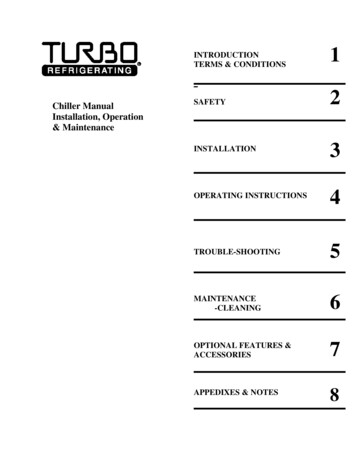
dEGFFCP11TcOUTOUTController Changing the factory chiller set points will result in non-warranty service calls. Lowering the SP1 setting could result innusiance low pressure trip.This document explain the functionality of the Drake Chiller Controller and Drake Remote Display Unit Version7.60 07/2013This control is powered by 24 VAC and provides control of up to two compressors by monitoring water temperatureand line pressure. Compressor control is accomplished via switching 24 VAC to the motor contactor. Run timecontrol parameters are user programmable and, once set and saved, are maintained in non-volatile memory. Pleaserefer to the programming section for more information on this topic. An optional remote display will be availablewhich provides remote display of system parameters.DRAKE CHILLER CONTROLLER OPERATION:Mains power switch is closed: Mains power is applied to the controller system transformer (24 VAC). The controller’s power supply is nowenergized and power is supplied to the pressure transmitters but all pumps and compressors remains off untilthe power switch on the panel is pressed. The control indicators have 3 reds dots illuminated in each display.Power On: Power switch on control is pressed and held for 5 seconds (Normal operation): All the control LED’s briefly flash as an indicator test, then the digital displays and the power indicator willilluminate. Any previous alarms are cleared. The top numeric LED will indicate the inlet water temperature andthe lower numeric LED will indicate the outlet water temperature. If the control has not been configured theletters “CFG” will appear on the upper 3-digit LED (This is a factory only function). The re-circulation pump is energized. There is no status LED for this pump. Any time the power is on, there circulation pump is on. If the inlet water temperature is above either setpoint plus differential, cooling will be called. After the compressordelay (30 seconds, fixed) the first compressor will energize. The “Compressor 1” green LED illuminates. Hot gas relay valves will all be energized 60 seconds after the compressor starts.(continued next page.)9.
If so equipped, the secondary compressor will energize based on the second setpoint and differential. The samedelays outlined for compressor #1 will be observed. To equalize compressor run time, periodically the primary andsecondary compressor assignments will switch. The LED will illuminate for the actual compressor in use. Shouldthe setpoints be set such that both compressors could be energized at the same time, a short delay will be imposedon the second compressor to reduce power line inrush to the chiller. Once the setpoint is achieved or surpassed the compressor will be de-energized. The hot gas relay will alsode-energize but the re-circulation pump will remain energized. The compressor will be available for another callimmediately, but will not engage until after the compressor delay time expires. When the inlet water setpoint plus differential is again exceeded, the compressor will again energize per theschedule listed above and the cycle will repeat. The compressors are rated for continuous duty and will runcontinuously if required.System Pump Control: Momentarily pressing the “pump” switch energizes the system pump relay. The “PUMP”LED illuminates. Momentarily pressing it again turns it off. Power Off: Press and hold the power switch. Afterholding the power switch for 5 seconds the compressor(s), the hot gas relays and the re-circulation pump willde-energize. The system pump will also de-energize. All control LED’s will turn off and the control will be off exceptall (and only) the decimal points on the numeric LED’s will be on. The pressure transducers will remain powered.The mains disconnect must be used to completely removecontrol power.ALARM CONDITIONS AND INDICATIONS: Temperature Sensor: If the temperature sensor transmits an out of range temperature it will be perceived asbad. “Err” will begin flashing in the upper numeric LED while one of the following will be displayed on the bottomnumeric LED: “tSi” for the inlet temperature sensor, and “tSo” for the outlet temperature sensor. The Drake ControlManual V740 Page 1 of 5 control will de-energize the compressors and hot gas valves and the alarm relay willenergize. The re-circulation pump remains energized. The fault is cleared by momentarily pressing the “Power”switch after the error has been resolved. It will not reset automatically. Pressure Sensor: If the voltage received from the pressure sensor(s) is .4vdc or 4.6vdc the pressure sensorwill be perceived as bad since it’s normal operating parameters are .5vdc to 4.5vdc. “Err” will begin flashing in theupper numeric LED while one of the following will be displayed on the bottom numeric LED: “tL1” for compressor1 low pressure sensor, “tL2” for compressor 2 low pressure sensor, “tH1” for compressor 1 high pressure sensor,and “tH2” for compressor 2 high pressure sensor. The compressor and hot gas valve will be de-energized and thealarm relay will energize. The fault is cleared by momentarily pressing the “Power” switch after the error has beenresolved. It will not reset automatically.10.(continued next page.)
High Temperature: If the outlet water temperature exceeds the setpoint for 10 seconds the “Hi Temp” LED willilluminate and the “Hi Temp” alarm parameter name will flash on the upper numeric LED, but the control willcontinue to function normally. The alarm relay is not affected by the High Temperature alarm and does not energize.The parameter name value will be displayed in the lower numeric LED. When the outlet water temperature recoversto below the setpoint the “Hi Temp” LED will turn off. Normal run display will resume. Low Temperature: If the outlet water temperature is less than the setpoint the “Lo Temp” LED will illuminate andthe “Lo Temp” alarm parameter name will flash on the upper numeric LED. The compressor will be de-energized andthe alarm relay energizes. The parameter value will be displayed in the lower numeric LED. When the outlet watertemperature recovers to above the set point the “Lo Temp” LED will illuminate steadily. The fault is cleared bymomentarily pressing the “Power” switch after the temperature is greater than the reset point. Once cleared thecontrol will attempt to function normally. It will not reset automatically. Water Flow: If the water flow drops below the point required to keep the flow switch closed, the “Lo Flow” alarmparameter name will flash on both numeric LED’s and the control will de-energize the compressors and hot gasvalves. The re-circulation pump remains energized. It will reset automatically.Review Mode: A review (read only) mode is available which will display the program variables and settings. Thecontrol will continue to run normally during the review mode. Use the UP or DN key to step through each parameter.There are six (6) additional parameters viewable; “Hi1”, “Hi2”, “Lo1”, “Lo2” (actual pressure readings) which appearfirst in the list, and “Hr1” and “Hr2” (compressor hours) which appear after the “LtA” setpoint. There is no “Upd”function in review mode. To exit the Review mode, momentarily press the “Set” key. There is no timeout toautomatically exit the review mode. Note: In the event of an alarm the Review mode will terminate and the controland alarm settings will be active.Programming: Press and hold both the “UP” and “DN” switches for 3 seconds to enter programming mode fromthe run mode. Control will continue to operate while changes are made using the existing parameters. The parametername will be displayed on the upper numeric LED and the parameter value will be displayed on the lower numericLED. Use the UP/DN keys to change the value, use the “Set” to keep that value and advance to the next parameter.T
of the chiller blocking air flow 4) Refrigerant overcharge . 5) Microprocessor is translating the incorrect system pressure Solution: (with the disconnect off) 1) Clean all debris off of the condenser co