Transcription
HPLC: High Pressure Liquid Chromatography2013 Chem 413IntroductionChromatography can be described as a mass transfer process involving adsorptionusing a nonpolar stationary phase and a mobile polar phase titrating through the column. Theactive component of the column, the sorbent or the stationary phase, is typically a granularmaterial made of solid particles (e.g. silica, polymers, etc.), 2-50 µm in size. The components ofthe sample mixture are separated from each other by means of mobile phase and differentdegrees of interaction with the sorbent particles based on their relative polarity. The pressurizedliquid is typically a mixture of solvents (e.g. water, acetonitrile and/or methanol). Its compositionand temperature plays a major role in the separation process by influencing the interactionstaking place between sample components and sorbent. These interactions are physical innature, such as hydrophobic, dipole-dipole or ionic.High performance liquid chromatography (HPLC) is a chromatographic technique usedto separate a mixture of compounds in analytical chemistry and biochemistry with the purposeof identifying, quantifying or purifying the individual components of the mixture. Before theinvention of HPLC, chemists had column chromatography at their disposal, and columnchromatography was time consuming.To speed up a classic column chromatography, chemists would have to use a shortcolumn for separation, however this lead to poor separation of molecular components heldwithin solution. The basic setup of a classic column chromatography would include the columnthat varied in I.D. from 10 to 50nm and column lengths of 50-500cm. The column was thenpacked with the stationary phase ranging in particle size from 150 to 200 µm thick. Chemists,wanting to speed the separation process up, first experimented with the introduction of avacuum source or a high pressure source. However, they found with the increased negative orpositive pressure, the column length would have to be increase linearly in order to acquire avalid separation that could be used for analytical data with a high confidence level. Chemistsrealized that with the development of pressurized systems, reducing the particle size wouldincrease the efficiency. It was not until the late 60’s that chemists and industrial engineeringprocess acquired adequate technology and manufacturing techniques to develop a smallergrained stationary phase that would be cohesive with a pressurized system. Today, HPLC hasmany uses including medical (e.g. detecting vitamin D levels in blood serum), legal (e.g.detecting performance enhancement drugs in urine), research (e.g. separating the componentsof a complex biological sample, or of similar synthetic chemicals from each other), and1
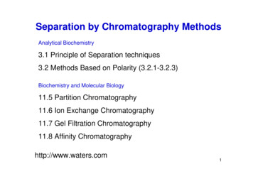
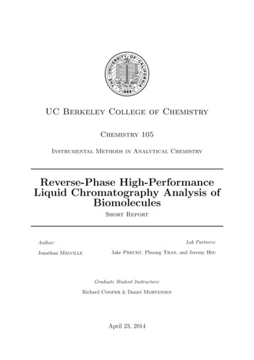
manufacturing (e.g. during the production process of pharmaceutical and biological products),(Kealey, 1987).Block Diagram and ExplanationA basic block diagram of an HPLC is shown in Figure 1.Figure 1: Block Diagram of an HPLCYour desired solvent mixture travels through capillary tubes, from the solvent reservoir to thepump, where it is becomes highly pressurized. The pump is also used to control the flow rate ofthe mobile phase substance,which is typically measured in mL/minute. The prepared sample isthen injected into the line, where it travels with the solvent into the HPLC column. There aremany different columns you can choose from, depending on the sample you want analyzed. Asthe solvent moves through the column, molecules from your sample will stick to the silica in thecolumn and detach at different times, making them distinguishable from one another. Thedetector detects when these molecules detach from the silica and reports the data in the form ofa chromatogram. Various types of detectors can be used such a UV-VIS, fluorescence, or anevaporative-light scattering detector (ELSD). Once the solvent has traveled through the columnit goes into a waste container, or can be collected if desired.The parameters of the HPLC, like any instrument, are important and are dependant onyour sample. The solvent mixture, containing a strong solvent and a weak solvent, will dependon whether your sample is polar in nature or not. Common solvents include water, methanol andacetonitrile. Two different solvent methods can be use, isocratic or gradient. With isocratic, thesolvent mixture stays the same, 50:50 for example. With a gradient, the solvent will start with a100:0 ratio of weak solvent:strong solvent and increase in increments over time to the final2
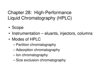
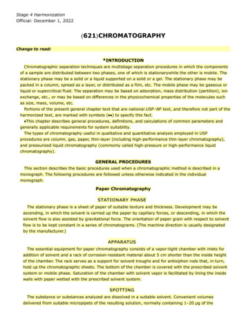
mixture ratio. It’s important to flush the system before running your samples in order to insurethat the solvents used for the previous sample does not interfere with your samples. The mobilephase flow rate is important and can range from 1-10 mL/min, though 1 mL/min is a good placeto start with most experiments. It’s important to monitor pressure when adjusting the flow rate,as the pressure should not exceed 400 bar. The injection can also vary in volume, anywherefrom 0.1-100.0 µL. For concentrated samples, 3-5 µL is appropriate and 25 µL for dilutesamples. Starting with an injection of 10 µL is typical. The temperature can be adjusted but formost samples 25 C is adequate. The temperature setting should never exceed 50-60 C. Youalso need to know what wavelengths in the UV-VIS spectrum you want to monitor. A diode arraydetector has a range of 210-400 nm and for samples, the default program setting are fine. TheHPLC at UAF is an Agilent 1100 Series and is located in downstairs instrument room. (Figure 2).Figure 2: Labeled Agilent 1100 Series HPLC at UAFHPLC data is given in the form of a chromatogram, which looks much like data fromother instruments. (Figure 3)3
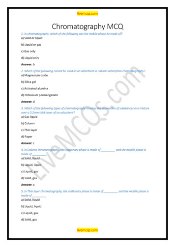
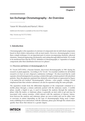
Figure 3: Example HPLC Chromatogram (Mixture of Perfume and Water)1The x-axis is labeled with a time unit, typically minutes, and the y-axis can be a variety of thingsdepending on the specifics of each experiment. For example, if you were using a UV-VISelement as a detector, the y-axis would be labeled absorbance. From the chromatogram,compounds can be both identified and their concentrations quantitated. The tools found withinthe HPLC software on the computer can be extremely useful in analyzing a chromatogram. Youcan determine peak height, peak area and also see the specific spectrum associated with agiven me-chromatogram.png4
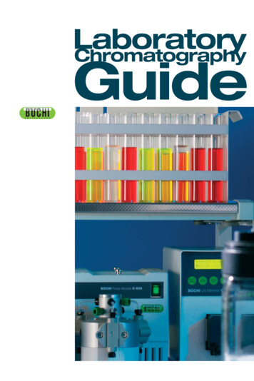
Individual Component sampler5
.6
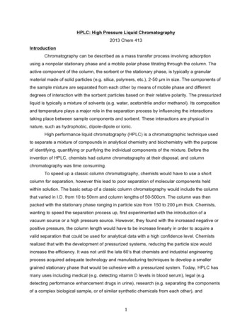
Figure8:Thediodearray.7
HPLC Instrument OperationSafety Precautions: Make sure all waste is properly disposed of in designated containers. Makesure you’ve reviewed the MSDS’s for the solvents that you are using.1. Check solvent bottles and waste container. Be sure the necessarysolvents are present and bottles are full. Also, note the location of thesolvent bottles (A1, A2, B1, B2) you will use (see diagram right). Allsolvents must be HPLC-grade and filtered. Also, make sure that yourwaste container has adequate space.2. Connect your column. After deciding which column you should use, mount it on thecolumn holder (Figure 2) and connect the injection and waste lines to the column. Thearrow(s) on the columnwill indicate the directionof flow. All connectionsto the pump should be finger tight.3. Add samples to autosampler. Insert your sample(s) into the autosampler and note ofwhich slot your samples are in.Samples that are to be analyzed with HPLC should have a concentration of about 1 mg/mL (ref).All samples must be filtered using a syringe and 25 µm filter (ref). Unfiltered samples run therisk of damaging the column. Degassed samples are best, as bubbles can cause complicationswith the instrument. The solvents used in preparing your samples should be the same mixtureas the mobile phase you plan to run through the column.4. Turn on the instrument in correct order. It is essential to turn on the components of theHPLC in the correct order:a. Enter your name and solventinformation in the log book.b. Log onto to computer.Username: Administrator andpassword: 3000hanover.c. Turn on the interface and waituntil it beeps and reads “not ready” ( 1 minute).d. Make sure that the interface and computer are communicating by looking at the CAGBootup server.8
e. Turn on the 5 components of theHPLC in order:i. column,ii. diode array,iii. autosampler,iv. pump, andv. degasser.Allow these systems to power up for2-3 minutes.f.Before you open the software onthe computer, allow time for theautosampler to stop moving.This indicates the instrument is ready. Click on the Instrument 1ONLINE icon on the desktop.g. If you plan to use the Evaporative Light Scattering Detector (ELSD):i.turn on the instrument by switch in the back.ii. turn on the gas tank near the instrument (flow should be 3.5bar or 51 psi)iii. Turn on lightiv. Temperature should be 60 C for a aqueous mobile phase and40 C for an organic mobile phase. Flow rate should be 1ml/ min.v. Connect the detector inlet after the UV detector.5. Flush lines with proper solvent mix. If you were not the last user, be sure to flush thelines with the solvent mixture you will be using. To do this,a. Disconnect column inlet and drain inlet line into a waste container.Cap the column so the column does not dry out.b. Select your solvent mixture. Under the Instrument tab at the top select “Set upPump”. This will bring you to the setup menu.i. Enter your desired flow rate, stop time, and solvent mixture. The flow shouldbe anywhere from 1-2 mL/min, depending on the manufacturerrecommendations for your specific column.9
ii. To change the solventmixture, adjust the percent ofsolvent B and the computerwill automatically adjust thepercent for solvent A.iii. Make sure that the numbersin the Timetable (outlined inred) match the numbersentered for time, %B, flowand max pressure above,otherwise the system will freak out. Hit “OK” and now you can flush the lines.iv. Under the Instrument tab at the top select “System On” to turn on the pump,thermostat and DAD. Allow the lines to flush until the pressure is stable.v. Once the lines are done flushing, you can turn off the pump by clicking on thepump icon and selecting “Controls”.vi. Select “Off” in the upper left hand corner and click OK. Once the pump is off,you can reconnect the injection line to the column.vii. Once the column is connected turn the pump back on by going back into thepump controls and selecting “On” then hitting “OK”. Monitor the pressure tomake sure it doesn’t exceed the specifications of your column.viii. If you are using the ELSD, connect it behind the UVdetector after flushing column for a few minutes.6. Create a method.a. Under the Method tab, select “Load Method,” or “New Method.”b. Under the Method tab, select “Edit Entire Method.” This will walkyou through the setup of your method.c. Edit “Edit Method” pop up window. Checkall boxes and click “OK.”d. Edit “Method Information.” Here you canmake notes about your sample, thesolvents used and any other informationyou might need. Click “OK.”10
e. Edit “Set up Pump.” These shouldbe the same parameters you usedto flush the lines. Be sure that theflow rate, solvent mixture, and maxpressure are the same in the topportion of the screen are the sameas in the “timetable” portion below.Click “OK.”f.Edit “Set up Injector.” This is the amount of yoursample that will be injected. Standard injectionvolumes are 3-5 µL (ref?). The optimization formost experiments can be set to “none”.g. Edit “ADC1 ADC Signal.” This window controls the Light Scattering Detector (ELSD).The default settings seem to function. Select “OK.”h. Edit “ADC1 Timed Event Table.”i.Edit “DAD Signals.” In this tab,select which wavelengths you want to monitor. You can monitor up to 5 wavelengthsat a time, A-E.Make sure that you have the boxes checked next to the wavelengths you wantto monitor.You can select UV and/or VIS lamps by checking the boxes next to them on the right.You can also select which spectra you want stored, but it’s a good idea to save it all.11
j.Edit “Column Thermostat Method.”Next you need to set up yourthermostat and select which columnyou are running.For most experiments 24*C is anacceptable temperature.Select either “Column 1” or “Column 2”from the drop down menu on the right.The injection lines for the respectivecolumns are labeled with small pieces ofcolored tape so you know when columnyou have connected, 1 or 2.k. Edit “Signal Details.” From the pulldownmenu, select which signals to monitor in themain window. Add a signal to your methodby selecting whichsignal you want in thepulldown menu andclicking “Add toMethod”. Click “OK.”l.Edit “IntegrationInformation.” Thedefault settings forthis are adequate sojust click “OK”.m. Edit “Specify Report.” The next step is the report menu.Select where and how you want your data to be saved. DONOT select to print your data since the instrument is nothooked up to a printer.Other than the “Destination” parameters, all the defaultsetting are adequate.n. Edit “Instrument Curves.” Select which signals you overlayedin the data report. For example, you can select the “Flow”12
option and a spectrum of the flow rate will beoverlayed on the spectral data collected from the UV.o. Edit “Run Time Checklist.” Enter any commands tobe carried out before or after you run a sample.Typically, these commands are unnecessary and youcan just leave it blank and select “OK”.p. Save your method. Under the Method tab select“Save Method” and you can name your method andsave it to a location of your choosing. Make sure thatyou don’t save over an existing method.7. Set up Sample Run.a. Load Method. Under method tab, click “Load Method.” Review your methodparameters by selecting “Edit Entire Method” under the Method tab.b. Next, go to the Instrument tab and select “System On”. This will turn on the pump,lamp and thermostat. This can also be done by clicking “on” button on the bottomright of the window showing the column conditions.8. Setting up a single sample.Start run by clicking on theSingle Sample Icon. From here,click on the vial icon, below thegreen “Start” button, and select9. “Sample Info”. From this menu,you can edit the informationabout your sample. You canedit the operator name, thesubdirectory where the file will be saved, the prefixand sample number for your sample, as well as anyadditional information in the bottom box. It’s a goodidea to make the prefix for the sample the date that itwas collected. You also need to input the location ofthe sample, the numbered slot your vial is in withinthe autosampler.13
Hit the green “Start” button. The data collected will appear on the screen and beautomatically saved to the location you designated previously.10. Setting up several samples. You can alsorun a sequence of samples, so long as they’reall using the same mobile phase.a. Under the Sequence tab, select“Sequence table.” Edit this table withthe appropriate information. Beespecially carful to selec theappropriate method and use thecorrect autosampler position.b. Select the sequence icon in the upperleft of the screen.c. Click the green “Start” button11. Running samples.a. Once the sample information has been entered and the system is on and ready torun a sample, many parts of the window will turn green. Including the autosampler,the instrument injector, column, and detector. Also the green box under the single/multiple sampler.b. the click the green “Start” button to start the run.c. Once a run has started, the green boxes will turn blue.14
12. Viewing your data. The data collected will appear on the screen and be automaticallysaved to the location you designated previously.You can also choose which spectra you want toview in the main window by clicking the “Change”button and adding or removing spectra from theviewing window. Pressure is one that you shouldalways be monitoring.13. Shut down Instrument. Before closing thesoftware, turn of the pump by clicking on thepump icon, selecting “Controls” and selectingthe “Off” option in the upper left-hand are ofthe screen. You can then exit the software.When asked if you’d like to turn off the pump,thermostat and lamp select “Yes”. Once the solware is closed, you can turn off theinstrument components and lastly the interface. You should turn off the instrument in thereverse order that you turned it on.Be sure to clean up the instrument area, empty waste bottles, remove your solventbottles, et when you are finished.14. Viewing and exporting your data. You can export the data that you collect from thecomputer as a CSV file to be opened in Excel later.a. Open the “Instrument 1 Offline” software. From here you can open your saved databy going to “File” and “Load Signal”. Find your saved data and select which sampledata you’d like to look at. All data is saved in the d:/ drive and within the “Data” folder.You should’ve created a folder when you ran your samples.If you have trouble connecting your data files to samples, use the “file information”button just below the files listed. This will give you the information from the file runsequence. With the file naming convention (ex: 001-0203) is the first three digitscorrespond to autosampler position (001) the next two (02) correspond to position inrun sequence, and the last two digits correspond to replicates (03).15
b. Once you have yourdata open, you can goto “File” then “Export”and select “CSV”. Abox will pop up andhere you can selectwhich signal you wantto export. Select the“Signal” option on theleft-hand side and clickOK.c. Make sure you note where the computer issaving the data to. Also, add a number after“export” in the file name, otherwise thesoftware will just keep replacing the same fileover and over. After that you can select whichsignal you want to export.d. Once you have exported the data, you cancopy the file to a flash drive to be opened inExcel later.16
TroubleshootingIn case of disaster contacts: Dr. Hayes, Dr, Iceman, Dr. Green or his lab members, Dr. Rasley.One of the most common errors in not turning on the instrument components in thecorrect order. Take the time to make sure you do this to avoid any problems. If the softwaregives you a specific error code, consult the various manuals, located in a big stack next to theHPLC computer, and once you find the specific error code, the manuals will walk you throughhow to correct the error. Otherwise Mike Jaramillo, Adai, and Professor Rasley can all help withthe HPLC.If the pressure randomly drops, this could indicate a leak. Make sure that no solvent drips ontothe instrument otherwise censors will register a leak and shut the instrument down.17
Instrument MaintenanceAlways make sure that you empty any waste containers after using the HPLC. It is agood idea to run a test for a column that hasn’t been used recently or is old, to make sure that itis working properly and hasn’t been contaminated.References Introduction to Modern Liquid Chromatography, 2nd ed,. New York: Wiley, 1979 S. Lindsay, High Performance Liquid Chromatography, New York, Wiley, 1992 Operating Manual, High Performance Liquid Chromatograph, Agilent 1100; VWD, DAD,FLD, and es/000/007/356/original Operating ManualHPLC 1100.pdf?1306827231 Jaramillo, Mike. SOP for Agilent 1100 Series HPLC Instrument18
High performance liquid chromatography (HPLC) is a chromatographic technique used to separate a mixture of compounds in analytical chemistry and biochemistry with the purpose of identifying, quantifyi