Transcription
Dell PowerEdge M1000eSystemsConfiguration Guide
Dell PowerEdge M1000eSystemsConfiguration Guide
Notes, Notices, and CautionsNOTE: A NOTE indicates important information that helps you make better use ofyour computer.NOTICE: A NOTICE indicates either potential damage to hardware or loss of dataand tells you how to avoid the problem.CAUTION: A CAUTION indicates a potential for property damage, personal injury,or death.Information in this document is subject to change without notice. 2008 Dell Inc. All rights reserved.Reproduction of these materials in any manner whatsoever without the written permission of Dell Inc.is strictly forbidden.Trademarks used in this text: Dell, the DELL logo, PowerEdge, and Dell OpenManage are trademarksof Dell Inc.; Microsoft, Windows, and Active Directory are either trademarks or registered trademarksof Microsoft Corporation in the United States and/or other countries.Other trademarks and trade names may be used in this document to refer to either the entities claimingthe marks and names or their products. Dell Inc. disclaims any proprietary interest in trademarks andtrade names other than its own.August 2008
Contents1About Your SystemSystem Overview. . . . . . . . . . . . . . . . . .7. . . . . . . . . . . . . . . . . . . . .7. . . . . . . . . . . . .10. . . . . . . . . . . . . . . . . . . . . . .11System Control Panel FeaturesLCD Module. . . . . . . . . . . . . . . .12. . . . . . . . . . . . . . . . . .13. . . . . . . . . . . . . . . . . . . . . . . . . .13LCD Module MenusBack-Panel FeaturesBladesCMC Module . . . . . . . . . . . . . . . . . . . . . . . . .17. . . . . . . . . . . . . . . . . .19CMC Daisy Chaining (Enclosure Stacking)iKVM Switch Module2Initial System ConfigurationBefore You Begin16. . . . . . . . . .21. . . . . . . . . . . . . . . . . . . .21. . . . . . . . . . . . . . .21. . . . . . . . . . . . . . . .21. . . . . . . . . . . . . . . . .21. . . . . . . . . . . . . . . . . .22Power Requirements .Network InformationInitial Setup SequenceConfiguring the CMCInitial CMC Network Configuration. . . . . . . .Logging in to the CMC Using the Web-BasedInterface . . . . . . . . . . . . . . . . . . .Adding and Managing CMC Users .22. . .25. . . . . . . .26Contents3
Configuring iDRAC Networking Using theWeb-Based Interface . . . . . . . . . . . . . .27Setting the First Boot Device for Servers. . . . .28. . . . . . . . .28Configuring and Managing PowerInstalling or Updating the CMC Firmware. . . . .29. . . .31. . . . . .31. . . . . . . . . . .31Configuring the Optional iKVM Switch ModuleEnabling iKVM Access to the Dell CMCConsole . . . . . . . . . . . . . . . . .Updating the iKVM Firmware .Tiering the Avocent iKVM Switch From anAnalog KVM Switch . . . . . . . . . . . .Tiering the Avocent iKVM Switch From aDigital KVM Switch . . . . . . . . . . . .3. . . . .3334. . . . . . . . . . . . . . . . . . . . . . .36Configuring the I/O ModulesOverview .32. . . . . . . . . .Viewing and Selecting ServersFlexAddress. . . . . . . . . . . . .37. . . . . . . . . . . . . . . . . . . . . . . .37Before You Begin. . . . . . . . . . . . . . . . . . . . . . . . . . . . . . . . . . .39. . . . . . . . . . . . . . . . . . . . .39Network InformationSwitch ModulesConfiguring a Switch Module Network EthernetPort Using the Web-Based Interface . . . . . .39. . .40. . . . . .42. . . . . . . . . . . . . . .43Cisco SFS M7000e Infiniband Switch ModulePowerConnect M6220 Ethernet SwitchModule . . . . . . . . . . . . . . . . .Cisco Ethernet SwitchBrocade M4424 SAN I/O Module4Contents39. . . . . . . . .45
Pass-through Modules. . . . . . . . . . . . . . . . .Ethernet Pass-through Module. . . . . . . . . .Fibre Channel Pass-through Module. . . . . . .Contents4747495
6Contents
1About Your SystemSystem OverviewYour system can include up to 16 half-height blades (server modules), eightfull-height blades, or a mixture of the two blade types (see Figure 1-1,Figure 1-2, and Figure 1-3). To function as a system, a blade is inserted into aenclosure (chassis) that supports power supplies, fan modules, a ChassisManagement Controller (CMC) module, and at least one I/O module forexternal network connectivity. The power supplies, fans, CMC, optionaliKVM module, and I/O modules are shared resources of the blades in theenclosure.Configuration Guide7
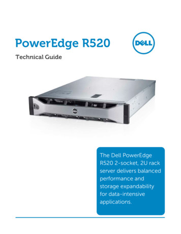
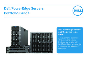
Figure 1-1. Blade Numbering – Half-Height Blades812345679101112131415Configuration Guide816
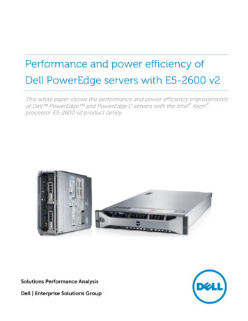
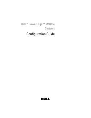
Figure 1-2. Blade Numbering - Full Height Blades12345678Figure 1-3. Blade Numbering - Mixed Full-Height and Half-Height Blades1234513614781516Configuration Guide9
System Control Panel FeaturesFigure 1-4 shows the control panel features on the M1000e enclosure frontpanel.Figure 1-4. Control Panel Features123451USB port (mouse only)2USB port (keyboard only)3video connector4system power button5system power indicatorNOTE: The USB and video ports are functional only if an optional iKVM module isinstalled.10Configuration Guide
LCD ModuleThe LCD module provides an initial configuration/deployment wizard, aswell as access to infrastructure and blade information and error reporting. SeeFigure 1-5.Figure 1-5. LCD Module2311LCD screen3selection ("check") button2scroll buttons (4)Configuration Guide11
LCD Module MenusMain MenuThe Main Menu options include links to the Server Menu, the EnclosureMenu, and the LCD Setup Menu.LCD Setup MenuYou can change the default language and startup screen for the LCD menuscreens using this menu.Server MenuFrom the Server Menu dialog box, you can highlight each blade in theenclosure using the arrow keys, and view its status. A blade that is powered off or booting is designated by a gray rectangle. Anactive blade is indicated by a green rectangle. If a blade has errors, thiscondition is indicated by an amber rectangle. To select a blade, highlight it and press the center button. A dialog boxdisplays the iDRAC IP address of the blade and any errors present.Enclosure MenuThe Enclosure Menu includes options for Module Status, Enclosure Status,and IP Summary. 12In the Module Status dialog box, you can highlight each component in theenclosure and view its status.–A module that is powered off or booting is designated by a grayrectangle. An active module is indicated by a green rectangle. If amodule has errors, it will be indicated by an amber rectangle.–If a module is selected, a dialog box displays the current status of themodule and any errors present. In the Enclosure Status dialog box, you can view the enclosure status, anyerror conditions, and power consumption statistics. The IP Summary screen shows IP information for the CMC(s), and theiDRAC of each installed server.Configuration Guide
Back-Panel FeaturesThe back of the M1000e enclosure supports six I/O modules, one or twoCMC modules, an optional iKVM module, nine fan modules, and six powersupply modules. Figure 1-6 shows a fully configured enclosure.Figure 1-6. Back-Panel Features2134561fan modules (9)2primary CMC module3I/O modules (6)4optional iKVM module5secondary CMC module6power supplies (6)BladesFigure 1-7 shows the front panel features on the M600 and M605 blades.Figure 1-8 shows the front panel features on the M905 and M805 blades.Configuration Guide13
Figure 1-7. Front Panel Features - PowerEdge M600 and M605126543141blade handle release button2hard drives (2)3blade status/identification indicator4USB connectors (2)5blade power button6blade power indicatorConfiguration Guide
Figure 1-8. Front Panel Features - PowerEdge M905 and M8051265431blade handle release button2hard drives (2)3blade status/identification indicator4USB connectors (3)5blade power button6blade power indicatorConfiguration Guide15
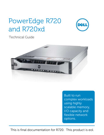
CMC ModuleFigure 1-9. CMC Module Features123451098671Ethernet connector Gb12Ethernet connector STK (used fordaisy-chaining CMCs in separateenclosures)3link indicator (2)4activity indicator (2)5DB-9 serial connector for localconfiguration6optional secondary CMC (CMC 2)7primary CMC (CMC 1)8amber fault indicator9blue status/identification indicator10power indicatorThe CMC provides multiple systems management functions for yourmodular server, including the M1000e enclosure’s network and securitysettings, I/O module and iDRAC network settings, and power redundancy andpower ceiling settings.16Configuration Guide
CMC Daisy Chaining (Enclosure Stacking)CMC daisy chaining can be utilized to minimize the number of networkconnections required for chassis (enclosure) management, such that only oneor two network connections (depending on whether or not redundant CMCsare installled) are needed for up to four M1000e enclosures.Cabling GuidelinesFollow these guidelines to daisy chain CMC modules from enclosure toenclosure: CMC Ethernet port "GB1" is the "Uplink" port. It will uplink to either themanagement network, or to receive a cable from the CMC Ethernet portlabeled "STK" in the adjacent enclosure.The CMC Ethernet port labeled "STK" is the "daisy-chain" port. It willonly connect to CMC port GB1 on the adjacent enclosure. Do not connectthis cable directly to the management network. Up to 4 enclosures can be daisy-chained. Enclosures can be daisy-chained in both redundant and non-redundantdeployments:–In a redundant CMC deployment, cable all CMC modules in the CMCprimary slots together. Cable all CMC modules in the CMC secondaryslots together. Do not connect the primary daisy chain with thesecondary daisy chain (do not “cross cable” the two sets of CMCs).–In a non-redundant CMC, cable all CMC modules in the CMCprimary slots together.Figure 1-10 shows four enclosures with redundant CMC modules installed.Primary CMC port GB1 in the first enclosure connects to the managementnetwork. Primary CMC port GB1 in the adjacent enclosure is "uplinked” intothe port labeled "STK" on the primary CMC in the enclosure above it. Nocable is required in port STK on the fourth enclosure in line. The samecabling scheme is valid for the daisy chain of CMC modules in the secondaryslot of the enclosures.Configuration Guide17
Figure 1-10. CMC Daisy-Chaining – Enclosure With Redundant CMC Modules123181Management network segment3CMC2 – cable from connectorGb1 to networkConfiguration Guide2CMC1 – cable from connectorGb1 to network
iKVM Switch ModuleThe optional Avocent iKVM analogue switch module provides connectionsfor a keyboard, video (monitor), and mouse. It includes the followingfeatures: Local iKVM access can be remotely disabled on a per blade basis, using theblade’s iDRAC interface (access is enabled by default).NOTE: By default (enabled), a console session to a given blade will beavailable to both the iDRAC interface and a iKVM (user connected to a blade'sconsole via iDRAC and the iKVM will see the same video and be able to typecommands). The iDRAC will If this sharing is not desired, this can be disabledvia the iDRAC console interface. The following connectors:–One VGA connector. The iKVM supports a video display resolutionrange from 640x480 at 60Hz up to 1280x1024x65,000 colors(noninterlaced) at 75Hz.–Two USB ports for keyboard and mouse.–RJ-45 ACI port for tiering with Dell and Avocent analog KVM andKVM over IP switches with ARI ports.NOTE: The iKVM USB ports do not support storage devices.NOTE: Although the ACI port is an RJ-45 connector and uses Cat5 (or better)cabling, it is not an Ethernet network interface port. It is only used forconnection to external KVM switches with Analog Rack Interface (ARI) ports,and does not support native KVM over IP. The iKVM can also be accessed from the front of the enclosure, providingfront or rear panel KVM functionality, but not at the same time. Forenhanced security, front panel access can be disabled using the CMC’sinterface.NOTE: Connecting a keyboard, video, and mouse to the enclosure front panelwill disable video output to the iKVM back panel port. It will not interruptiDRAC video and console redirection. You can use the iKVM to access the CMC using the Command-LineInterface. For more information, see "Using the iKVM Module" in theCMC User’s Guide.Configuration Guide19
Figure 1-11 shows the external features of the iKVM module.Figure 1-11. Avocent iKVM Switch Module325411identification indicator2status indicator3ACI port for tiering connectiononly4USB connectors (2) for keyboardand mouse5video connectorNOTICE: Do not connect the ACI port to a LAN device such as a networkhub. Doing so may result in equipment damage.20Configuration Guide
Initial System Configuration2Before You BeginPower RequirementsNOTICE: The enclosure power supplies must be connected to a Type B orpermanently-connected PDU, not directly to an electrical outlet. The powersupplies require a 200–240 V power source.Network InformationIf your network uses static addressing, you will need the IP address, subnetmask, and gateway to configure the CMC and other modules in the enclosure.Initial Setup Sequence1 Unpack the enclosure and install it in a rack.See the Getting Started Guide and Rack Installation Guide for moreinformation.NOTICE: Do not power-on the blades (server modules) until you have configuredthe switch modules, as described in "Configuring the I/O Modules" on page 37.2 Connect power to the power supplies.NOTICE: The power supplies must be connected to a PDU, not directly to anelectrical outlet. The power supplies require a 200–240 V power source.3 If an optional iKVM module is installed, connect the keyboard, video, andmouse to the enclosure control panel (see Figure 1-4) or to the iKVMmodule (see Figure 1-11).NOTE: Connecting a keyboard, video, and mouse to the enclosure front panelwill disable video output to the iKVM back panel port.Configuration Guide21
4 Press the power button on the enclosure control panel. See Figure 1-4.5 Configure the CMC network settings.The LCD Configuration Wizard allows you to quickly configure the CMCand iDRAC management interfaces and on the network, so you can thenmanage the enclosure remotely. See "Configuring the CMC NetworkSettings Using the LCD Configuration Wizard" on page 23.You can also use a management station and the RACADM CLI toconfigure the CMC. See "Configuring the CMC Network Settings Using aManagement Station and CLI" on page 24.6 Configure the IO modules at this time to allow proper network or storagemanagement or paths. See "Configuring the I/O Modules" on page 37.7 Once the Ethernet and Fibre Channel switches are configured and able topass traffic, you can then power on your server blades. This will allow timefor the Ethernet switch to boot and allow PXI \ UNDI traffic for all blademodules.Configuring the CMCInitial CMC Network ConfigurationConnecting to the CMC Using a Network Connection and the Default IP Address,or a User-Defined IP AddressThe CMC is preset for DHCP. To use a static IP address you must toggle theCMC setting from DHCP to a static address by either running the LCDConfiguration Wizard, or by using a management station and CLIcommands.If toggled to use a static address, the CMC IP address will default to thestandard IP address settings of 192.168.0.120, 255.255.255.0, and gateway of192.168.0.1. You can change this address to an IP address of your choosing.See "Configuring the CMC Network Settings Using the LCD ConfigurationWizard" on page 23 for initial configuration instructions. If you prefer to use amanagement station and CLI, see "Configuring the CMC Network SettingsUsing a Management Station and CLI" on page 24.22Configuration Guide
Configuring the CMC Network Settings Using the LCD Configuration WizardWhen you first start up your system, the screen on the LCD module willdirect you to configure the CMC network settings.NOTE: The option to configure the server using the LCD Configuration Wizard isonly available until the CMC is connected to the network or the default password ischanged. Once the CMC is accessible from the network, the LCD panel cannot beused to reconfigure the CMC. Thereafter, use the RACADM CLI or the web-basedGUI to change the CMC settings.Table 2-1 lists the keys that you use to view or change information on theLCD module screens.Table 2-1. LCD Module Screen Navigation KeysKeysActionLeft and right arrowsMove between screens.Up arrow or down arrowMove to the previous or next option on a screen.Center buttonSelect and save an item and move to the nextscreen.1 Choose a language from the options presented in the dialog box.2 Start the LCD Configuration Wizard.3 Configure the CMC network settings for your network environmentNOTE: The CMC external management network mode is set by default toDHCP. To use a static IP address, you must change the setting using the LCDConfiguration Wizard.–Network speed–Duplex mode–Network mode (DHCP or static)–Static IP address, subnet mask, and gateway values (if static mode wasselected)–DNS setting, including a registered CMC name, (if DHCP mode wasselected)Configuration Guide23
4 If desired, configure the iDRAC network setting for DHCP mode.NOTE: You cannot set a static IP address for the iDRAC using the LCDConfiguration Wizard. See "Configuring iDRAC Networking Using the WebBased Interface" on page 27.5 Review the settings on the Network Summary screen.–If the settings are correct, press the center button to close theconfiguration wizard and return to the Main Menu.–If the settings are not correct, use the left arrow key to return to thescreen for that setting and correct it.After you complete the LCD Configuration Wizard, you can access the CMCon the network using the Web-based CMC interface or text-based interfacessuch as a serial console, Telnet, or SSH.Note that if you intend to use static addresses rather than DHCP to accessthe iDRACs, you must configure them using the CMC Web-based interfaceor CLI.Configuring the CMC Network Settings Using a Management Station and CLIThe LCD Configuration Wizard is the quickest way to initially configure theCMC network settings. However, you can also use a management station andand a local connection to access the CMC. There are two ways to create alocal connection to the CMC: The CMC Console via the optional iKVM. Press Print Screen andselect blade number 17. Blade number 17 is a direct local connection tothe CMC. Serial connection using a null modem cable (115200 bps, 8 Data bits, noparity, 1 stop bit, and no flow control).Once you have established a connection to the CMC, you can complete theinitial CMC network configuration:1 Log into the CMC.The default user name is root and the default password is calvin.2 Type getniccfg and press Enter to view the current CMC networkparameters.24Configuration Guide
3 Configure the CMC network settings:–To set a static IP address, typesetniccfg -s IP address network mask gateway and press Enter .Use the appropriate settings for your network.–To configure the CMC to obtain an IP address using DHCP, typesetniccfg -dand press Enter .4 To activate the new network settings, typeracadm racresetand press Enter .Logging in to the CMC Using the Web-Based Interface1 Open a supported Web browser window.For more information, see "Supported Web Browsers" in the CMC User’sGuide.2 Login to the CMC.–If the CMC is accessed using a specific IP address, type the followingURL In the Address field, and then press Enter :https:// CMC IP address The default IP address for the CMC is 192.168.0.120. If the defaultHTTPS port number (port 443) has been changed, type:https:// CMC IP address : port number where IP address is the IP address for the CMC and portnumber is the HTTPS port number.–If you access the CMC using a registered DNS name, type the CMC’sname:https:// CMC name By default, the CMC name on the DNS server is cmc- servicetag .Configuration Guide25
3 The CMC Login page appears.NOTE: The default CMC user name is root, and the password is calvin. Theroot account is the default administrative account that ships with the CMC. Foradded security, you should change the default password of the root account duringinitial
Cisco SFS M7000e Infiniband Switch Module. . . 40 PowerConnect M6220 Ethernet Switch . available to both the iDRAC interf ace and a iKVM (user connected to a blade's console via iDRAC and the iKVM will see the s