Transcription
FSELPROCEDURE FORCOMPRESSION TESTING OFCONCRETE CYLINDERS AND CORES1. PROCEDURE OVERVIEWThis procedure is to be used for determining the compressive strength of concrete cylinders and cores.After preparing the ends, a compressive axial load will be applied to the samples at a continuous rateuntil failure occurs. The compressive strength will be determined by dividing the maximum load bythe cross-sectional area of the sample. ASTM C39 (Ref. 7.1) and ASTM C42 (Ref. 7.2) formed the basisfor the development of this procedure.Two concrete test machines are available for use in FSEL. The main body of this procedure is applicableto both test machines. There are two appendices with each appendix containing detailed instructionsfor one of these two machine.The test machine located in the corner of the Room 180 is a Forney model FX-250T-TPilot machinewith a compressive force capacity of 300,000 lbs. The FX-250T is an open-loop machine that requiresthe user to monitor and adjust the load rate to satisfy ASTM C39 (Ref. 7.1) requirements. The machinenearest the bay door in Room 180 is a Forney model FX-500-Auto-MOE with a compressive forcecapacity of 500,000lbs. The FX-300-Auto is a closed loop machine that can internally monitor andadjust load rates to comply with testing standards.1.1.Student Responsibilities: 1.2.Read and understand the requirements of this procedureProvide concrete cylinders or cores for testingDispose of cylinders and cores after testingClean-up of the test machine after useStaff Responsibilities: Read and understand the requirements of this procedureAssist students with testing as neededEnsure concrete test machines are calibrated on an annual basis2. EQUIPMENT AND TOOLS Diamond End Grinding Machine Compression Testing Machine Pi Tape RulerRev. 0 Calipers Camera Assorted Test Fixtures Brush and Dustpan1
PROCEDURE FORCOMPRESSION TESTING OFCONCRETE CYLINDERS AND CORESFSEL3. MATERIALS Concrete Samples (Cores, Cylinders, or Both)4. PERSONAL PROTECTIVE EQUIPMENT Safety Glasses Safety Shoes Dust Mask Work Gloves5. DETAILED PROCEDURE5.1.Verify that the compression-testing machine is in working order and that it has been calibratedper FSEL operating procedure.The compression-testing machine should be calibrated on an annual basis. It should also benoted that calibration of these machines is limited to 100,000 lb of compressive force due tothe size of the compressive machine and the size of the calibration load cells available at FSEL.5.2.Prepare concrete samples for compression testing.5.2.1. Verify that the compressive strength samples do not have any significant defects thatmay affect the quality of the test results5.2.2. Use a diamond end grinding machine as necessary to square off and flatten each ofthe sample ends to meet the tolerances of ASTM C39 (Ref. 7.1).Diamond end grinding of the sample ends may be completed well in advance (e.g. upondemolding) of compression testing. Information about grinding cylinder and core endscan be found in the FSEL Procedure for Grinding the Ends of Concrete Cylinders andCores.Sulfur mortar caps prepared in accordance with ASTM C617 (Ref. 7.4) are a suitablealternative to the use of an end grinding machine. The sample length must be recordedprior to preparing the sulfur caps.5.2.3. Use calipers or a ruler to measure the sample length (𝐿𝐿) according to the guidance ofASTM C1542 (Ref. 7.3).Measure the length of the cylinder or core at four locations separated by 90 degreesaround the perimeter. Measurements should be taken to the nearest 0.01 in. if usingcalipers or to the nearest 1/16 in. if using a ruler or tape measure.Rev. 02
FSELPROCEDURE FORCOMPRESSION TESTING OFCONCRETE CYLINDERS AND CORES5.2.4. Use a pi tape to measure the sample diameter (𝐷𝐷) and subsequently calculate thelength-to-diameter ratio and cross-sectional area (𝐴𝐴).Measure the sample diameter at midheight to the neatest 0.01 in.5.2.5. If the length-to-diameter ratio (𝐿𝐿 𝐷𝐷) exceeds 2.1, shorten the sample through furthergrinding until the sample length is between 1.9 and 2.1 times the diameter.A length-to-diameter ratio less than 1.9 is acceptable by not desirable. Correctionfactors are provided in Article 5.5.2 and Table 2.5.2.6. Record the sample identifier, final sample length, sample diameter, length-todiameter ratio, and cross-sectional area for each cylinder or core tested.5.3.Prepare the compression-testing machine.5.3.1. Install bearing blocks and other test fixtures as necessary to successfully completecompression testing of the samples.5.3.2. Turn on the compression-testing machine and allow the electronic and hydraulicsystems to equalize for a minimum of 15 minutes.Equalization of the electrical and hydraulic systems is necessary to ensure stablereadings and repeatable results. Detailed instructions for operating the FX-250T testmachine are provided in Appendix A and detailed instructions for operating the FX-500test machine are provided in Appendix B.5.4.Test each concrete sample as soon as practicable after removal from its previous state ofconditioning.5.4.1. Wipe the concrete sample as necessary to remove any surface moisture.5.4.2. Wipe clean the bearing faces of the upper and lower bearing blocks and place thesample on the lower bearing block.5.4.3. Using the concentric circles on the bearing block and lower platen as points ofreference, carefully align the axis of the sample with the upper spherical seat.5.4.4. Tilt the spherically seated block so that the bearing face is parallel to the top surfaceof the sample.Rev. 03
FSELPROCEDURE FORCOMPRESSION TESTING OFCONCRETE CYLINDERS AND CORES5.4.5. Zero the force readout of the compression-testing machine and prepare the machinefor testing.Detailed instructions for operating the FX-250T test machine are provided in AppendixA and detailed instructions for operating the FX-500 test machine are provided inAppendix B.5.4.6. Apply load continuously at a rate of movement corresponding to a stress rate on thesample of 35 7 psi per second; refer to corresponding load rates in Table 1.Table 1 - Rate of LoadingNominal Sample Diameter3 in.4 in.6 in.Stress Rate35 7 psi/sLoad Rate250 50 lb/s440 90 lb/s900 200 lb/sDetailed instructions for operating the FX-250T test machine are provided in AppendixA and detailed instructions for operating the FX-500 test machine are provided inAppendix B.5.4.7. Continue to apply load until the sample fails and displays a well-defined fracturepattern.5.4.8. Record the maximum load carried by the sample during the test and note the type offracture pattern (refer to Figure 1).If the fracture pattern is not one of the typical patterns shown in Figure 1, record adescription of the failure pattern. The fracture pattern should also be documented witha camera.5.4.9. Photograph the failed test specimen.5.5.Calculate the compressive strength of the cylinder or core.5.5.1. Calculate the compressive strength of the sample by dividing the maximum load bythe cross-sectional area as determined from the measurements taken in Article 5.2.4.5.5.2. If the length of the sample was not greater than 1.75 times the diameter of the sample,correct the compressive strength by applying the appropriate correction factor ofTable 2; interpolate as necessary.Rev. 04
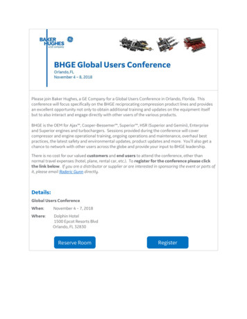
PROCEDURE FORCOMPRESSION TESTING OFCONCRETE CYLINDERS AND CORESFSEL5.5.3. Correct the measured compressive strength of cored samples as noted in ACI 214.4R(Ref. 7.6) and other applicable industry guidance.5.5.4. Record the compressive strength of each sample to the nearest 10 psi and note anycorrections made.5.6.Clean the test machine after testing.5.6.1. Discard the tested cylinder in the hopper located in the concrete testing room.If the hopper is full or nearly full, notify FSEL technical staff so that the hopper can beemptied.5.6.2. Clean all concrete dust and debris from the test machine.5.7.Power off the test machine.Type 1Type 2Type 3Reasonably well-formed coneson both ends, less than 1 in. ofcracking through capsWell-formed cone on one end, verticalcracks running through caps, no welldefined cone on other endColumnar vertical crackingthrough both ends, nowell-formed conesType 4Type 5Type 6Diagonal fracture with no crackingthrough ends; tap with hammerto distinguish from Type 1Side fractures at top orbottom (occur commonlywith unbonded caps)Similar to Type 5 butend of cylinder ispointedFigure 1 - Schematic of Typical Fracture PatternsRev. 05
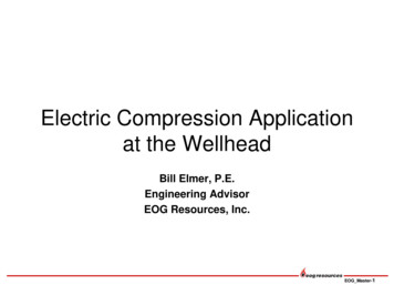
FSELPROCEDURE FORCOMPRESSION TESTING OFCONCRETE CYLINDERS AND CORESTable 2 - Correction Factors for L/D Ratios Less than 2.0𝐿𝐿 𝐷𝐷 Ratio1.751.501.251.00Correction Factor0.980.960.930.876. SUPPORTING DOCUMENTSNone.7. REFERENCED DOCUMENTS7.1.ASTM C39-12: Compressive Strength of Cylindrical Concrete Specimens. West Conshohocken:ASTM International, 2012.7.2.ASTM C42-12: Obtaining and Testing Drilled Cores and Sawed Beams of Concrete. WestConshohocken: ASTM International, 2012.7.3.ASTM C1542-02: Measuring Length of Concrete Cores. West Conshohocken: ASTMInternational, 2002.7.4.ASTM C617-11: Capping Cylindrical Concrete Specimens. West Conshohocken: ASTMInternational, 2011.7.5.ACI Committee 214. ACI 214.4R-10: Guide for Obtaining Cores and Interpreting CompressiveStrength Results. Farmington Hills: American Concrete Institute, 2010.7.6.ACI Committee 214. ACI 214.4R-10: Guide for Obtaining Cores and Interpreting CompressiveStrength Results. Farmington Hills: American Concrete Institute, 2010.Rev. 06
FSELPROCEDURE FORCOMPRESSION TESTING OFCONCRETE CYLINDERS AND CORES8. RECORD OF REVISIONSRevisionDateAffected PagesDescription02016-10-21AllInitial IssueRev. 07
PROCEDURE FORCOMPRESSION TESTING OFCONCRETE CYLINDERS AND CORESFSELA. INSTRUCTIONS FOR USE OF FX-250T TEST MACHINE5.3.2To turn on the FX-250T machine, toggle the pump power switch and press the digitalpower switch. The digital power switch should illuminate and the pump should beaudibly running.5.4.5To zero the force and ready the machine for the first test preform the following steps:1.2.3.4.5.6.7.8.9.10.11.12.13.14.15.Tare the system by pressing “0 / Zero”;Press play - Display “RUN ”;Press Enter - Display “Compression ”;Press Enter - “Cube ”;Press Play - “Cylinder ”;Press Enter - “Edit Test ID”;Press play - “Edit Specimen”;Press Enter - “Dia 4.00000in”;Press Play - “Len 8.00000in”;Press Play - “Corr. 1.00000”;Press Play - “Wt 8.4000lb”;Press Play - “Age 28.0000days”;Press Play - “Rate 35.0 psi/s”;Press Play - “Exit”; andPress enter.Note: The default Test ID is 0. If multiple specimens are tested, the Test ID will need tobe incremented with each test. It is recommended that the default value for steps8through 12 be left in place. Diameters and lengths as measured per this procedureshould be used for all calculations after the test is completed.5.4.6To perform the compression tests, perform the following steps:1.2.3.4.5.6.7.8.Briefly move lever to full advance to close gap;After gap is nearly closed ( 1/8 in.), move the lever to “Hold”;Press “8/Stress” twice to show the load rate in psi/s;Close and latch the door to the test frame;Move lever to metered advance;Adjust the load rate using the knob/valve;After failure move lever to “Hold”;Move lever to “Retract” to retract the piston until a visible gap between thespecimen and test platen appears;9. Move the lever to “Hold”; and10. Press “7/Force” then “9/Peak” to show peak force.Rev. 08
PROCEDURE FORCOMPRESSION TESTING OFCONCRETE CYLINDERS AND CORESFSELNotes: During testing, the load rate will be displayed along with one of the followingsymbols: ---, -- , -, ###, , , or . Minus (-) signs indicate the load rate is less thanspecified, plus signs ( ) indicate the load rate is greater than specified, and pound signs(###) indicate the load rate is approximately correct. The more minus (-) or plus ( )signs, the further out of tolerance the load rate. After the cylinder or core reaches itspeak stress and prior complete failure, the load rate may begin to go negative. If thishappens, leave the rate control valve in its current state until visible failure of thespecimen.To perform an additional test with the same input values for diameter, length, loadrate, etc.:1.2.3.4.5.Rev. 0Press “-/New” - Display “Test ID”;Press Enter – Type the sequential test number;Press Enter;Press Play, andGo to the Appendix A section for Article 5.4.6 and repeat.9
FSELPROCEDURE FORCOMPRESSION TESTING OFCONCRETE CYLINDERS AND CORESB. INSTRUCTIONS FOR USE OF FX-500 TEST MACHINE5.3.2To turn on the FX-500 machine use the toggle switch near the lower left corner of thedisplay. The display should power on and the onboard computer should start.Log in to the machine using your User ID and PIN. After logging into the machine, checkand update the user information as needed. When the information is completed, click“Done.”Select “Cylinder” for the dropdown menu at the upper right corner of the screen.Confirm the data displayed on the right side of the screen. It is recommended that thenominal diameter and height of the specimen be entered rather than those measuredper this procedure. The load rate, or “ramp” should be 35 psi/s per the ASTM C39 (Ref7.1). The default preload is set 10,000 lbf (or 796 psi on a 4 in. cylinder). If you expectyour cylinder to fail near or less than this value, you should reduce the preload to amore appropriate level.Rev. 05.4.5Confirm that the load displayed is 0 lbf. If the load is not 0 lbf, click the “Tare Load”button on the screen.5.4.6To begin the test, click and hold “Jog Advance” to raise the testing table. Hold “JogAdvance” until the top of the cylinder or core is less than 1/8 in. from the upper testplaten. Click the “Start Test” button to begin the compression test. The test machinewill automatically apply the specified preload then begin applying load at the ratespecified in Article 5.4.6. After the test is complete and the sample is failed, choose theimage corresponding go the corr
After preparing the ends, a compressive axial load will be applied to the samples at a continuous rate until failure occurs. The compressive strength will be determined by dividing the maximum load by the cross-sectional area of the sample. ASTM C39 (Ref. 7.1) and ASTM C42 (Ref. 7.2) formed the basis for the development of this procedure. Two concrete test machine s are available for use in .