Transcription
DYNAMIC MODEL REVIEW GUIDELINE FORINVERTER BASED INTERCONNECTIONREQUESTSWhite Paper byCalifornia ISODCR Transmission, LLCGridliance West LLCPacific Gas and Electric CompanySan Diego Gas and Electric CompanySouthern California EdisonValley Electric Association, IncJUNE 2, 2021
DYNAMIC MODEL REVIEW GUIDELINE FOR INVERTER BASED INTERCONNECTION REQUESTSTable of Contents1.Introduction . 12.Model Usability Requirement . 13.General Modeling Requirements . 14.Generator Equivalencing. 25.Dynamic Model Description and Applicability . 46.Scaling PMAX and MVA Base for Equivalent Generator Size . 67.Primary Frequency Response Requirement . 78.Automatic Voltage Regulation Requirement . 89.Ride-Through Requirement . 910. Revision History . 1211. References . 12
1. IntroductionThe guideline is developed from WECC Solar Photovoltaic Power Plant Modeling and ValidationGuideline[1] and incorporated the CAISO interconnect requirements for inverter-based generators. Thepurpose of guideline is to promote good practice of model development by the interconnectioncustomers, facilitate consistent model reviews by the transmission planners and ensure the inverterbased generators meet various interconnection requirements. As the technology evolves, so does themodeling technique. It is important to understand the concepts and principles in this guideline andadapt to any particular configuration of an inverter-based power plant.2. Model Usability RequirementFirst of all, the power flow and dynamic models for any type of generators must be usable by thesoftware platform to perform the simulation. The usability requirement includes three aspects:1) All the models and associated parameters are read by the simulation software 1 correctly.a. The number of each power flow element, such as buses, lines, transformers,generators, shunts and etc., matches the number in the epc file.b. Parameters read into the software match the values in the epc file.c. The number of dynamic models read into the software matches the number of dynamicmodels in the dyd file.d. Parameters read into the software match the values in the dyd file. 22) There is no initialization errors for the dynamic models and the warning messages are reviewedwith resolution or explanation.3) The models produce flat lines for a 20-second no-disturbance simulation. The CAISO definitionof flat lines is variations of generator outputs Pgen and Qgen over 20 seconds are less than1MW and 1Mvar respectively, or 1%.3. General Modeling RequirementsThe modeling requirements in WECC Solar Photovoltaic Power Plant Modeling and Validation Guidelineare adopted for all inverter-based power plants and provided below.The power flow model for an inverter-based power plant includes: An explicit representation of the interconnection transmission line;An explicit representation of all station transformers;An equivalent representation of the collector systems;An equivalent representation of inverter pad-mounted transformers with a scaled MVA rating;An equivalent representation of generators scaled to match the total capacity of the plant; andThe CAISO and Participating TO’s use GE PSLF platform to perform the dynamic simulation. The models should beprovided in GE PSLF format, i.e. epc for power flow and dyd for dynamic model.2GE PSLF reads dynamic model parameters by the sequence in the dyd entry. The parameter names in the dyd fileare for readability, not an identifier. It is a common mistake that the parameters are not provided in the sequencespecified in the GE PSLF manual.1Page 1 of 14
DYNAMIC MODEL REVIEW GUIDELINE FOR INVERTER BASED INTERCONNECTION REQUESTS An explicit representation of all plant-level reactive compensation devices either as shunts (fixedor switchable) or as generators (FACTs devices), if applicable.For integrated inverters and pad-mounted transformers, the manufacturer’s test and data are providedat the terminal of the integrated unit of inverter and pad-mounted transformer. Inverter control inputsare also taken from the terminal of the integrated unit. In such case, the pad-mounted transformers arenot explicitly modeled in the power flow model. Instead, the integrated units are modeled by theequivalent generator.The dynamic model includes: A generator/converter module representing the typical solar PV inverter in the plant, scaled-upto match the plant’s aggregate nameplate rating;A local electrical control module which translates real and reactive power references intocurrent commands;A plant-level control module which sends real and reactive power references to the localelectrical controller, if the plant-level control is put in place; andFrequency and voltage protection modules, which show inverter protection settings underabnormal frequency and voltage conditions.4. Generator EquivalencingThe determination of single or multiple generator equivalence should take into account the number ofthe main substation transformers, the collector system behind each main substation transformer, theplacement of different makes of inverters behind the main substation transformers, the settingdifference among inverters, and the mix of different inverters. Each substation transformer is explicitly represented in the power flow model.If the same inverters are installed behind the substation transformer, represent the inverterswith one equivalent collector circuit, one equivalent pad-mounted transformer, and oneequivalent generator.If different inverters with the same control and protection setting are installed behind onesubstation transformer, represent all inverters by one equivalent collector circuit, oneequivalent pad-mounted transformer, and one equivalent generator.If inverters with different settings are installed behind the same substation transformer, modeleach type of inverter that has at least 10 MVA installed capacity using one equivalent generatorwith its own equivalent pad-mounted transformer. Any inverters with less than 10 MVAinstalled capacity may be aggregated with another type of inverter in one equivalent generator.Generator Equivalencing for Hybrid Power PlantsThere are two types of electrical configuration of hybrid plants – ac coupled or dc coupled. If differentfuel type each has its own set of inverters, i.e. ac coupled, each fuel type should be modeled explicitly byseparate equivalent generators, equivalent pad-mounted transformers and equivalent collectors. Thereactive capability requirement applies to the entirety of the hybrid plant. Each fuel type individuallymay not have capability to meet the requirement alone.
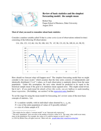
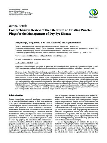
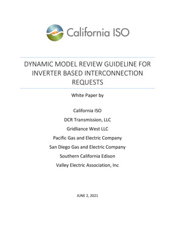
DYNAMIC MODEL REVIEW GUIDELINE FOR INVERTER BASED INTERCONNECTION REQUESTSIf different fuel types are behind the same inverters, i.e. dc-coupled, the equivalent generatorrepresents the inverters as looking from the ac side and become a hybrid generator. A negative Pmin ofthe equivalent generator represents the maximum charging power if the battery storage charges fromthe grid.Figure 1: Single-Generator Equivalent Power Flow Representation for a Solar PV Power mountedTransformer5PVPoint ofInterconnectionEquivalent PVGeneratorPlant-levelReactiveCompensation(if applicable)Figure 2: Multiple-Generator Equivalent Power Flow Representation for a Solar PV Power mountedTransformer5P1EquivalentGenerator forPV Make 1Point ofInterconnection678P29P3EquivalentGenerator forPV Make 2EquivalentGenerator forPV Make 3
DYNAMIC MODEL REVIEW GUIDELINE FOR INVERTER BASED INTERCONNECTION REQUESTS5. Dynamic Model Description and ApplicabilityThe WECC approved dynamic models required to represent inverter-based resources (IBRs) are shown inTable 1 and the most common forms of IBR technologies that utilize these models are type 3 and 4 windturbine generators (WTGs), solar PV resources, and battery energy storage systems (BESS).General model description: REGC is used to represent the generator/converter model. It processes the real (Ipcmd) andreactive (Iqcmd) current commands from the REEC model and controls the output of real (Ip)and reactive (Iq) current injection to the grid. REEC is used to represent the electrical control model. It processes the active (Pref) and reactive(Qref) power reference from the REPC model, with feedback from the terminal voltage (vref0)to control the real (Ipcmd) and reactive (Iqcmd) current commands to the REGC model. REPC is used to represent the plant-level controller. It processes voltage and reactive poweroutput to emulate plant-level volt/VAR control. It also processes frequency and active poweroutput to emulate plant-level active power control. This model provides active (Pref) andreactive (Qref) power reference to the REEC model. LHVRT is used to represent a protection function that trips the resource for defined low andhigh voltage conditions. LHFRT is used to represent a protection function that trips the resource for defined low and highfrequency conditions. WTGT A is used to represent the wind turbine. It processes the generator electrical power andinitial mechanical torque, and outputs the turbine speed to the WTGP A model and thegenerator speed to the WTGQ A and REEC model. WTGAR A (named WTGA A in PSLF) is used to represent the turbine aerodynamics. Itprocesses the wind turbine blade pitch angle and outputs the mechanical torque to theWTGT A model. WTGPT A (named WTGP A in PSLF) is used to present the pitch controller. It processes theturbine speed and power order to provide the turbine pitch angle to the WTGA A model. WTGTRQ A (named WTGQ A in PSLF) is used to represent the torque controller. It processesthe generator speed and initial power reference to provide power reference to the REEC model.Mathematically, only REGC and REEC are required to run the simulation. However, the purpose of themodeling is to accurately capture the performance of the IBR plants. All models representing the actualplant controls are required. The REPC model is required for all IBR plants that have a power plantcontroller (PPC) and all the WT* models are required for Type 3 WTGs because they are part of the windturbine controls that affect the dynamic response. A monitored branch should always be defined in therepc * models.
DYNAMIC MODEL REVIEW GUIDELINE FOR INVERTER BASED INTERCONNECTION REQUESTSTable 1: Applicable WECC Approved IBR Dynamic ModelsDescriptionModelApplicability Notesregc aAll IBRregc bAll IBR, voltage source interface to grid for numericalrobustnessreec aType 3 and 4 WTGSolar PVDC-coupled: BESS not charging from gridreec cStand-alone BESSDC-coupled: BESS charging from gridreec dAll IBR, enhanced modeling capability from reec a andreec brepc aFor single generator control(except for plant level PF control)repc bFor single and multiple generator controlRide-throughprotectionlhvrtVoltage ride-throughlhfrtFrequency ride-throughDrive-trainwtgt aType 3 WTGType 4 WTG if pflag 1 in reec aTurbine aero-dynamicswtga aType 3 WTGPitch controlwtgp aType 3 WTGTorque controllerwtgq aType 3 WTGConverteraElectrical controlbPlant controllercModel Selection Notesa. Both REGC A and REGC B are valid models for any type of IBR. REGC B is proper if any of themodeling enhancement features are needed. Refer to reference [4] for details of REGC Bmodeling enhancement. The CAISO and PTO may also request replacement of REGC A withREGC B if numerical issues are encountered and can be resolved by voltage source interface.b. REEC D model can be used for any type of IBR. However, REEC A and REEC C are still validmodels. REEC D is proper if any of the modeling enhancements are needed. Refer to reference[4] for details of REEC D modeling enhancement. To model momentary cessation, REEC D isrequired in the future model submission.c. REPC B shall be used when multiple generators receive the P and Q references from thecommon power plant controller. REPC B could coordinate controls among generators and othervar devices. For hybrid interconnection requests, REPC B shall be used to coordinate controls
DYNAMIC MODEL REVIEW GUIDELINE FOR INVERTER BASED INTERCONNECTION REQUESTSand enforce plant level limits. Refer to Reference [5] for more details. REPC B may also be usedfor single generator representation for the plant level power factor control. Plant level powerfactor control is acceptable only in coordination with the inverter level voltage regulation suchthat the plant meets the voltage regulation requirement below. REPC B uses system MVA base(100 MVA). All per unit parameters in REPC B shall be provided on the system MVA base (100MVA).6. Scaling PMAX and MVA Base for Equivalent Generator SizePower flow modelThe maximum active power output (Pmax) for an equivalent generator is based on the sum of theassociated individual inverter MW output 3 to achieve the desired MW at the POI.The total MVA base of an equivalent generator is based on the sum of all the associated individualinverter MVA ratings.Dynamic modelMajority of the parameters in the dynamic models are expressed in per unit and are determined basedon the generator MVA base. Therefore, the MVA base used in the dynamic models should be consistentwith the value used in the power flow model, except for the REPC B model, which uses the system MVAbase (i.e. 100 MVA). Pmax/Pmin and Qmax/Qmin in REPC B models are relative limits, i.e.[repc b].pmax (pmax – pgen)/100[repc b].pmin (pmin – pgen)/100[repc b].qmax (qmax – qgen)/100[repc b].qmin (qmin – qgen)/100where pmax/pmin and qmax/qmin on the right side are plant level limits and may not be equalto the sum of individual equivalent generation limits. For example, pmax corresponds to themaximum plant output achieving the maximum allowed MW injection at the Point ofInterconnection.Given that these parameters depend on the generation dispatch which is unknown to theInterconnection Customers or Generator Owners, it is agreed that the parameters are set as if pgen 0and qgen 0 by the IC or GO. A pre-run epcl will offset the parameters by actual pgen and qgen whenperforming studies.REPC A model has a parameter puflag that allows the model being on the model MVA base or systemMVA base. If puflag is set to 0, the inputs pbranch and qbranch are on system MVA base and theparameters should be on system MVA base as well. It is recommended to set puflag to 1 to avoidinconsistent parameters.The individual inverter MW output is often lower than the individual rated MW output, due to the practice ofoversizing inverters.3
DYNAMIC MODEL REVIEW GUIDELINE FOR INVERTER BASED INTERCONNECTION REQUESTS7. Primary Frequency Response RequirementIBRs executing Generation Interconnection Agreement or filing unexecuted Generator InterconnectionAgreement at FERC on or after May 15, 2018 are required to provide active power primary frequencyresponse capability with a 5% droop for both under 4 and over-frequency conditions, and a maximumdeadband of 36 mHz. The required control options to simulate the primary frequency response ingovernor power flow and dynamic simulations are shown below.Power flow model: base load flag (BL)Base load flag descriptions are as follows: BL 0: Pgen can be dispatched downward and upward; this is the expected setting for BESS andmay also be used for solar or wind resources if they will carry headroom for low frequencyresponse. BL 1: Pgen can be dispatched downward only; this is the typical setting for solar or windresources as they usually do not have headroom for low frequency response. BL 2: Pgen is fixed; this is not compliant with the requirement.Dynamic model: REPCActive power primary frequency response is controlled by the plant-level controller (REPC) model.Dynamic model parameter descriptions are as follows: Frqflag: Governor response; disable (0) or enable (1) Ddn: Down regulation droop response to over-frequency condition (20 on the generatornameplate capacity base for 5% droop) Dup: Up regulation droop response to under-frequency condition (20 on the generatornameplate capacity base for 5% droop) Fdbd1: Over-frequency deadband for governor response (-0.0006 p.u./36mHz) Fdbd2: Under-frequency deadband for governor response (0.0006 p.u./36mHz)Since REPC B is on the system MVA base, ddn and dup in REPC B should be converted by a factor of: 𝑎𝑎𝑎𝑎𝑎𝑎 𝑔𝑔𝑔𝑔𝑔𝑔𝑔𝑔 𝑜𝑜𝑜𝑜 𝑅𝑅𝑅𝑅𝑅𝑅𝑅𝑅 ��𝐺𝐺𝐺𝐺𝐺𝐺𝐺 𝑃𝑃𝑃𝑃𝑃𝑃𝑃𝑃 /100The active power control weighting factor Kzi should be set toAlthough IBRs are required to provide primary frequency response, they may not be able to respond to underfrequency conditions, since these resources are typically operated at maximum available active power with noheadroom.4
DYNAMIC MODEL REVIEW GUIDELINE FOR INVERTER BASED INTERCONNECTION ��𝐺𝐺𝐺𝐺𝐺𝐺𝐺𝑖𝑖 𝑃𝑃𝑃𝑃𝑃𝑃𝑃𝑃/ 𝑎𝑎𝑎𝑎𝑎𝑎 𝑔𝑔𝑔𝑔𝑔𝑔𝑔𝑔 𝑜𝑜𝑜𝑜 𝑅𝑅𝑅𝑅𝑅𝑅𝑅𝑅 ��𝐺𝑡𝑡𝑡𝑡𝑡𝑡 𝑃𝑃𝑃𝑃𝑃𝑃𝑃𝑃A recent modeling enhancement has been made to distinguish the frequency response capability fromthe frequency response availability in operation. Ddn and dup represent the capability of the inverterswithout considering operational headroom. BL flag represents the availability of operational headroom.If BL is 1, upward frequency response is blocked by setting Pmax to Pgen in the simulation.Table 2: Primary Frequency Response Settings Required for New Interconnection RequestsFunctionalityDown regulation only(wind or solar)Up and down regulation(wind, solar, BESS orhybrid)BLfrqflag110ddndup 20 or 20 orequivalent equivalenton theon themodelmodelMVA base MVA basefdbd1fdbd2[-0.0006,0)(0, 0.0006]IBRs executing Generation Interconnection Agreement or filing unexecuted Generator InterconnectionAgreement at FERC prior to May 15, 2018 do not have the primary frequency response requirement.The baseload flag and repc * model should reflect the field settings and the IBR operation.8. Automatic Voltage Regulation RequirementIBRs that are subject to FERC Order 827 5 are required to operate in automatic voltage control mode tosupport voltage regulation and voltage stability. There are several valid control modes available tocontrol voltage, using different combinations of pfflag, vflag and qflag in the REEC model and refflag inthe REPC model. However, not all meet the automatic voltage regulation requirements. Table 3 lists allthe compliant plant-level voltage control mode combinations. Other plant-level voltage control modecombinations not shown in Table 3 are invalid.Dynamic model parameter descriptions are as follows: Pfflag: Local power factor flag; voltage or reactive power control (0); power factor control (1) Vflag: Local voltage control flag; voltage control (0); reactive power control (1) Qflag: Local reactive power control flag; constant power factor or reactive power control (0);voltage
dynamic model review guideline for inverter based interconne ction requests If different fuel types are behind the same inverters, i.e. dc-coupled, the equivalent generator represents the inverters a