Transcription
Fluke Networks DTX-1800 DTX-GFM SpecsProvided by www.AAATesters.comDTX-MFM/GFM/SFMFiber ModulesUsers ManualPN 2142235April 2004, Rev. 1 11/04 2004 Fluke Corporation. All rights reserved. Printed in USA.All product names are trademarks of their respective companies.
LIMITED WARRANTY AND LIMITATION OF LIABILITYEach Fluke Networks product is warranted to be free from defects in material and workmanship under normal use and service. The warrantyperiod for the mainframe is one year and begins on the date of purchase. Parts, accessories, product repairs and services are warranted for90 days, unless otherwise stated. Ni-Cad, Ni-MH and Li-Ion batteries, cables or other peripherals are all considered parts or accessories. Thewarranty extends only to the original buyer or end user customer of a Fluke Networks authorized reseller, and does not apply to any product which, in Fluke Networks’ opinion, has been misused, abused, altered, neglected, contaminated, or damaged by accident or abnormalconditions of operation or handling. Fluke Networks warrants that software will operate substantially in accordance with its functionalspecifications for 90 days and that it has been properly recorded on non-defective media. Fluke Networks does not warrant that softwarewill be error free or operate without interruption.Fluke Networks authorized resellers shall extend this warranty on new and unused products to end-user customers only but have no authority to extend a greater or different warranty on behalf of Fluke Networks. Warranty support is available only if product is purchasedthrough a Fluke Networks authorized sales outlet or Buyer has paid the applicable international price. Fluke Networks reserves the right toinvoice Buyer for importation costs of repair/replacement parts when product purchased in one country is submitted for repair in anothercountry.Fluke Networks' warranty obligation is limited, at Fluke Networks' option, to refund of the purchase price, free of charge repair, or replacement of a defective product which is returned to a Fluke Networks authorized service center within the warranty period.To obtain warranty service, contact your nearest Fluke Networks authorized service center to obtain return authorization information, thensend the product to that service center, with a description of the difficulty, postage and insurance prepaid (FOB Destination). Fluke Networks assumes no risk for damage in transit. Following warranty repair, the product will be returned to Buyer, transportation prepaid (FOBDestination). If Fluke Networks determines that failure was caused by neglect, misuse, contamination, alteration, accident or abnormalcondition of operation or handling, or normal wear and tear of mechanical components, Fluke Networks will provide an estimate of repaircosts and obtain authorization before commencing the work. Following repair, the product will be returned to the Buyer transportationprepaid and the Buyer will be billed for the repair and return transportation charges (FOB Shipping Point).THIS WARRANTY IS BUYER'S SOLE AND EXCLUSIVE REMEDY AND IS IN LIEU OF ALL OTHER WARRANTIES, EXPRESS OR IMPLIED, INCLUDINGBUT NOT LIMITED TO ANY IMPLIED WARRANTY OF MERCHANTABILITY OR FITNESS FOR A PARTICULAR PURPOSE. FLUKE NETWORKS SHALLNOT BE LIABLE FOR ANY SPECIAL, INDIRECT, INCIDENTAL OR CONSEQUENTIAL DAMAGES OR LOSSES, INCLUDING LOSS OF DATA, ARISINGFROM ANY CAUSE OR THEORY.Since some countries or states do not allow limitation of the term of an implied warranty, or exclusion or limitation of incidental or consequential damages, the limitations and exclusions of this warranty may not apply to every buyer. If any provision of this Warranty is heldinvalid or unenforceable by a court or other decision-maker of competent jurisdiction, such holding will not affect the validity or enforceability of any other provision.4/04Fluke NetworksPO Box 777Everett, WA 98206-0777USA
Table of ContentsTitleOverview of Features.Registration .Contacting Fluke Networks .Accessing the Technical Reference Handbook .Additional Resources for Cable Testing Information.Unpacking .DTX-MFM Multimode Fiber Modules.DTX-GFM Multimode Fiber Modules .DTX-SFM Singlemode Fiber Modules .Safety Information.Getting Acquainted .Installing and Removing Fiber Modules .Physical Features .Essentials for Reliable Fiber Test Results.Cleaning Connectors and Adapters.iPage112223334466788
DTX-MFM/GFM/SFM Fiber ModulesUsers ManualAbout Setting the Reference .Using Mandrels for Testing Multimode Fiber .Testing Your Patch Cords .Fiber Test Settings .Certifying Fiber Cabling .Autotest in Smart Remote Mode .Autotest in Loopback Mode .Autotest in Far End Source Mode .Using the Visual Fault Locator .Monitoring Optical Power .Options and Accessories.Maintenance.Replacing Fiber Patch Cords.Using the Smart Remote with an OptiFiber Certifying OTDR .Certification, Compliance, and Regulatory Information .Appendix A: Test Method Reference Tables.Indexii91011121717222833363942424243A-1
List of 3.14.15.16.17.Installing and Removing Fiber Modules .Fiber Module Features .Wrapping a Patch Cord Around a Mandrel.Example of How to Determine the Number of Adapters Setting .Equipment for Testing in Smart Remote Mode .Smart Remote Mode Reference Connections (Modified Method B).Smart Remote Mode Test Connections (Modified Method B).Equipment for Testing in Loopback Mode .Loopback Mode Reference Connections (Modified Method B) .Loopback Mode Test Connections (Modified Method B) .Equipment for Testing in Far End Source Mode .Far End Source Mode Reference Connections (Modified Method B).Far End Source Mode Test Connections (Modified Method B).Equipment for Using the Visual Fault Locator .Using the Visual Fault Locator.Equipment for Monitoring Optical Power.Connections for Monitoring Optical Power .67111417192123252728313233353638iii
DTX-MFM/GFM/SFM Fiber ModulesUsers Manualiv
DTX-MFM/GFM/SFM Fiber ModulesOverview of Features The DTX-MFM, DTX-GFM, and DTX-SFM fiber modulesare used with a DTX Series CableAnalyzer to test andcertify fiber optic cabling installations. The fiber modulesoffer the following functions and features:Visual fault locator helps you locate breaks, badsplices, bends, and check fiber continuity andpolarity. FindFiber function helps you identify and verifyfiber connections. RegistrationMeasures optical power loss and length on dualfiber cabling. The DTX-MFM tests multimode cablingat 850 nm and 1300 nm. The DTX-SFM testssinglemode cabling at 1310 nm and 1550 nm. TheDTX-GFM features a VCSEL LED for testingmultimode cabling at 850 nm and 1310 nm forGigabit Ethernet applications. Each module transmits both wavelengths (850 nmand 1300 nm, 850 nm and 1310 nm, or 1310 nm and1550 nm). Provides pass/fail results based on industry-standardlimits.Registering your product with Fluke Networks gives youaccess to valuable information on product updates,troubleshooting tips, and other support services. Toregister, fill out the online registration form on the FlukeNetworks website at www.flukenetworks.com/registration.1
DTX-MFM/GFM/SFM Fiber ModulesUsers ManualContacting Fluke NetworksNoteIf you contact Fluke Networks about your tester,have the tester's software and hardware versionnumbers available if s.com 1-425-446-4519 Australia: 61 (2) 8850-3333 or 61 (3) 9329 0244 Beijing: 86 (10) 6512-3435 Brazil: 11 3044 1277 Canada: 1-800-363-5853 Europe: 44 1923 281 300 Hong Kong: 852 2721-3228 Japan: 81-3-3434-0181 Korea: 82 2 539-6311 Singapore: 65-6738-5655 Taiwan: (886) 2-227-83199 USA: 1-800-283-5853Visit our website for a complete list of phone numbers.2Accessing the Technical ReferenceHandbookThe DTX Series CableAnalyzer Technical ReferenceHandbook provides additional information on the testerand the fiber modules. The handbook is available on theDTX CableAnalyzer Product CD included with yourmodules and on the DTX CableAnalyzer product page onthe Fluke Networks website.Additional Resources for CableTesting InformationThe Fluke Networks Knowledge Base provides answers tocommon questions about Fluke Networks products, alongwith articles on cable testing techniques and technology.To access the Knowledge Base, log on towww.flukenetworks.com, then click knowledge base atthe top of the page.The website cabletesting.com provides articles on testing,documentation, and standards, answers to commonquestions about cable testing, a glossary, and otherreference information.
UnpackingUnpackingThe fiber modules come with the accessories listed below.If something is damaged or missing, contact the place ofpurchase immediately.DTX-MFM Multimode Fiber Modules Two DTX-MFM Fiber Modules for testing at 850 nmand 1300 nm Two SC/SC adapters Four 62.5/125 µm multimode patch cords, 2 m, SC/SC Two 62.5/125 µm multimode patch cords, 0.3 m, SC/SC Two gray mandrels for 62.5 /125 µm fiber with 3 mmjackets DTX-MFM/GFM/SFM Fiber Modules Users Manual DTX CableAnalyzer Product CD LinkWare Software CDDTX-GFM Multimode Fiber Modules Two DTX-GFM Fiber Modules for testing at 850 nmand 1310 nm (for Gigabit Ethernet applications) Two SC/SC adapters Four 50/125 µm multimode patch cords, 2 m, SC/SC Two 50/125 µm multimode patch cords, 0.3 m, SC/SC DTX-MFM/GFM/SFM Fiber Modules Users Manual DTX CableAnalyzer Product CD LinkWare Software CD3
DTX-MFM/GFM/SFM Fiber ModulesUsers ManualDTX-SFM Singlemode Fiber Modules Two DTX-SFM Fiber Modules for testing at1310 nm and 1550 nm. Two SC/SC adapters Four 9/125 µm singlemode patch cords, 2 m, SC/SC Two 9/125 µm singlemode patch cords, 0.3 m, SC/SC DTX-MFM/GFM/SFM Fiber Modules Users Manual DTX CableAnalyzer Product CD LinkWare Software CDNoteThe patch cords provided are suitable for testingSC-terminated links. Other patch cords arerequired for other connector types or 50 /125 µmfiber. Many are available as accessories fromFluke Networks.4Safety InformationWX WarningTo avoid possible fire, electric shock, or personalinjury read the safety information given in theDTX Series CableAnalyzer Users Manual.W* Warning: Class 1 and Class 2 LaserProductsTo avoid possible eye damage caused byhazardous radiation: Never look directly into optical connectors. Somesources produce invisible radiation that canpermanently damage your eyes. Keep the fiber module’s OUTPUT port coveredwith a dust cap or keep a patch cord attached.The OUTPUT port may be active even when atest is not in progress. Covering the port reducesthe risk of accidental exposure to hazardousradiation. Never start a test or activate the OUTPUT port orVFL port without first connecting a fiber to theport you will use.
Safety Information Never look directly into the visual fault locatoroutput. Momentary exposure to the locator’soutput will not damage your eyes; however,direct, long-term exposure is potentiallyhazardous. Do not use magnification to view the opticaloutputs without proper filtering. Use of controls, adjustments, or procedures notstated herein might result in hazardousradiation exposure. Use a Fluke Networks FiberInspector VideoMicroscope to periodically inspect the fibermodule’s OUTPUT connector for scratches andother damage. Do not use a video microscope to inspect thefiber module’s INPUT connector. This connectorhas different dimensions than the OUTPUTconnector, and may be damaged by a fiberinspection probe.CautionTo avoid damaging the tester or cables undertest, to avoid data loss, and to ensure maximumaccuracy of test results: Leave the module bay covers in place when thefiber modules are not installed. Turn off the tester before attaching or removingmodules. When using the fiber modules, use propercleaning procedures to clean all fiber connectorsbefore every use. Neglecting this step or usingimproper procedures can cause unreliable testresults and may permanently damage theconnectors.5
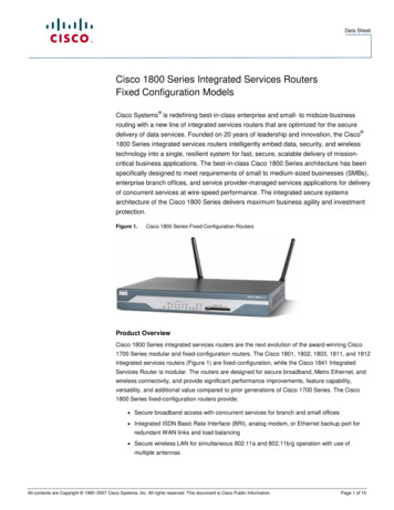
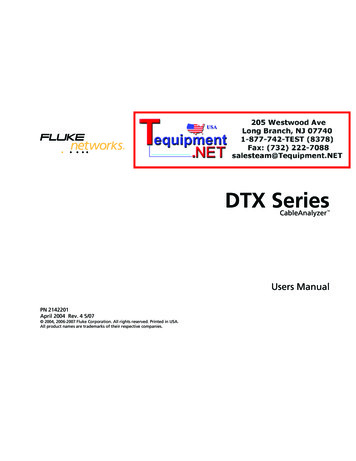
DTX-MFM/GFM/SFM Fiber ModulesUsers ManualGetting AcquaintedThe following sections introduce the fiber modules’features.Installing and Removing Fiber ModulesFigure 1 shows how to install and remove the fibermodules.CautionLeave the module bay covers in place when thefiber modules are not installed.CautionTurn off the testerbefore attaching orremoving modules.amd34f.epsFigure 1. Installing and Removing Fiber Modules6
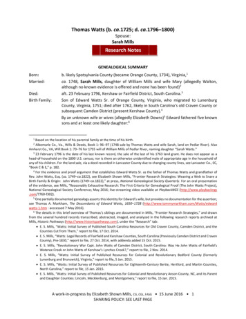
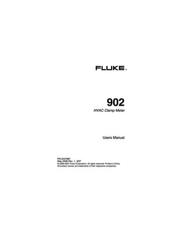
Getting AcquaintedPhysical FeaturesBC DA Button for activating the visual fault locator (B) and output port (D). SeeE“Using the Visual Fault Locator” on page 33 and “Autotest in Far End SourceMode” on page 28.AB Universal fiber connector (with dust cap) for the visual fault locator output.The connector accepts 2.5 mm ferrules. The LED below the connectorindicates the locator’s mode (continuous or blinking).C SC input connector with dust cap. Receives optical signals for loss, length,and power measurements.amd64f.epsD SC output connector with dust cap. Transmits optical signals for loss andlength measurements.W* WarningNever look directly into opticaloutput connectors (B and D).Some sources produceinvisible radiation that canpermanently damage youreyes.The LED below the connector is red when the output is transmitting themodule’s shorter wavelength, and green for the longer wavelength.E Laser safety label (shown at right).amd128i.epsFigure 2. Fiber Module Features7
DTX-MFM/GFM/SFM Fiber ModulesUsers ManualEssentials for Reliable Fiber TestResults Bulkhead connectors: Dip the tip of a foam swab inalcohol; then touch the swab to a dry wipe. Touch anew, dry swab to the alcohol spot on the wipe. Pushthe swab into the connector; twist it around 3 to 5times against the endface, then remove and disposeof the swab. Dry the connector with a dry swab bytwisting it around in the connector 3 to 5 times. Inspect connectors with a fiber microscope, such asthe Fluke Networks FiberInspector Video Microscopebefore making connections.To get reliable fiber test results, you must follow propercleaning and referencing procedures and, in some cases,use mandrels during testing.Cleaning Connectors and AdaptersAlways clean and inspect fiber connectors before makingconnections. Use 99 %-pure isopropyl alcohol andoptical-grade wipes or swabs to clean connectors asfollows: Connector ends: Wipe the end of the ferrule with aswab or wipe lightly moistened with alcohol. Drywith a dry swab or wipe.NoteUse a 2.5 mm foam swab for cleaning thetester’s optical connectors.8Periodically clean fiber adapters with a swab and alcohol.Dry adapters with a dry swab before use.Always cover unused connectors with dust caps or plugs.Clean dust plugs periodically with a swab or wipe andalcohol.
Essentials for Reliable Fiber Test ResultsAbout Setting the ReferenceThe reference serves as the baseline power level for lossmeasurements. Regular referencing helps account forminor variations in source power and connectionintegrity. Also, since the reference is the baseline formeasurements, the losses of the patch cords and adaptersused during referencing are excluded from test results.NoteTurn on the tester and smart remote and letthem sit for 5 minutes before setting thereference. Allow additional time if the moduleshave been stored above or below ambienttemperature.You should set the reference at these times: At the beginning of each day using the remote endsetup (Figures 7 through 13) you will use that day. Anytime you reconnect a patch cord to the module’soutput or other source. Anytime the tester warns you that the reference isout of date. Anytime you see a negative loss measurement. (Seethe Technical Reference Handbook for moreinformation.)You must set the reference at these times: Anytime you change the fiber module in the testeror smart remote. Anytime you start using a different smart remote. Anytime you change the Test Method in Setup. Twenty-four hours after the reference waspreviously set.Reference values should not change by more than a fewtenths of a dB from day to day. Larger changes mayindicate a problem with the patch cords or connections.See the sections on Smart Remote, Loopback, and FarEnd Source modes for details on setting the reference foreach mode.9
DTX-MFM/GFM/SFM Fiber ModulesUsers ManualUsing Mandrels for Testing Multimode FiberYou should use mandrels when testing multimode fiberwith the DTX-MFM fiber modules. Mandrels can improvemeasurement repeatability and consistency. They alsoallow the use of LED light sources to certify 50 µm and62.5 µ
Users Manual 4 DTX-SFM Singlemode Fiber Modules Two DTX-SFM Fiber Modules for testing at 1310 nm and 1550 nm. Two SC/SC adapters Four 9/125 µm singlemode patch cords, 2 m, SC/SC Two 9/125 µm singlemode patch cords, 0.3 m, SC/SC DTX-MFM/GFM/SFM Fiber Modules Users Manu