Transcription
NOTE: These kits are notlegal for use on pollutioncontrolled vehiclesUltimate LS SystemInstruction manual for theUltimate LS Induction SystemThis quick start manual is designed to get you up and running with your Ultimate LS Induction System. This system isready to go with everything needed to complete the induction system of your LS engine and get you on the road easierand faster than any system on the market today. Suitable for your new or pull-out LS engines to ensure you are up andrunning in a flash. For technical assistance with your Ultimate LS System, call 951-340-2624 or go online towww.fitechefi.com under “tech center”.Warning: Caution must be observed when installing any product involving fuel system parts or gas tank modifications.Work in a well ventilated area with an approved fire extinguisher readily available. Eye protection and other safety apparelshould be worn to protect against debris and sprayed gasoline. Ensure to disconnect the negative terminal of the batterybefore beginning. We recommend having this installation performed by an experienced, qualified, and FiTech approvedautomotive technician. The finished installation must be thoroughly checked for any fuel system leaks. All safety precautions must be observed when working with fuel. Lastly, ensure the engine has had sufficient time to cool! The coolant maystill be hot. Disregarding any of this information can result in serious injury or death.EMISSIONS EQUIPMENT:Not legal for use on pollution controlled vehicles: FiTech’s Ultimate LS System is not CARB approved for use on emissioncontrolled vehicles. This system is designed to control the EFI and ignition on LS based engines being retrofit into oldervehicles that do not require emission controls.Dimension Intake manifold is 6.5”Throttle body will clear any stock truck accessories depending on the type of water pump, if there is truck waterpump accessory clearance interference you will need to get a new water pump bracketThrottle body sits at 7 degreesBefore installing your FiTech Intake manifold it is recommended to check hood clearance. this can be done in afew simple steps. First, using modeling clay or putty, not included, make a small cone about 2-3 inches high. Position thecones on the top of the throttle body. Close the hood to locked position and re-open. The height of the cones indicate the amount of clearancebetween the hood and the air cleaner. Record these measurements. We recommend An inch of clearance. lay a meter stick across the fenders over the engine bay to ensure the throttle body sits below the fenders. Modification of the hood might be necessary to ensure there is no damage to any components.1
Kit contents 500HPIdle Air Control MotorIdle Air Temperature SensorWide band O2 SensorStainless Oxygen Sensor bung KitAN fittings and fuel crossoverFuel rail contents:Mounting bracket-6 AN fittingsRailsScrews to mount bracketsAN fittings and fuel crossoverKit contents 750 HpIdle Air Temperature SensorTwo Wide band O2 SensorStainless Oxygen Sensor bungTwo programmable fan control outputsFuel rail contents:Mounting bracket-6 AN fittingsRailsScrews to mount bracketsAN fittings and fuel crossover92MM Billet Aluminum Throttle BodyHand-held Controller with color touch screen and cableWindshield mount for touch screen controller36 lb/hr InjectorsLS ECUHigh volume fuel railsFabricated Aluminum Intake Manifold and boltsPlug and Play Primary Wiring Harness3 BAR MAP SensorThrottle Position Sensor102MM Billet Aluminum Throttle BodyHandheld Controller with color touch screen55 lb/hr InjectorsHigh volume fuel railsFabricated Aluminum Intake Manifold and boltsPlug and Play Wiring Harness3-BAR MAP SensorThrottle Position SensorIdle Air Control SensorParts required, not included: Coil packs Supported Fuel System Optional throttle cable mounting bracket (FiTech part number 67001)2
Table of ContentsEmission EquipmentDimensionsKit Contents: 500hpKit Contents:750hpParts required, not includedModified EnginesFeaturesEngine Protection FeatureSpecial InstructionInstall The Intake ManifoldInstall The Throttle BodyInstall Fuel RailsWiring SystemWiring DiagramVSSMain PowerAccessory WiresRed WireOrange WireTrans ControlFuse BoxCoil DCoil PK nockinj Pinj DCKPCAMALTCTSIATMAPIACTPSFinal StepsInitial ProgrammingHand-held controllerTiming ControlRev LimiterOn-Engine AdjustmentsPower AdderCrank SensorCam SensorWide Band O2Transmission ControlFuel Pump Pulse Width ModulationAir Fuel 1121212121313131314141414141415151516171717183
Modified EnginesThe Ultimate LS intake manifolds are designed to provide maximum performance for street/performance engine applications. The intake manifold will have the best fitment when the engine block and cylinder heads are machined to standardOE dimensions. If the engine block or cylinder head deck surfaces have been milled significantly, the alignment of themounting bolt holes and the port flange openings to the cylinder head may be shifted and not match-up satisfactorily. Ifyour engine has had the cylinder head or engine block deck surfaces milled, the following may be necessary for proper intake manifold installation. The bolt holes in the intake manifold would have to be slotted to allow the fastener to properlypass through the manifold mounting holes. The mounting fasteners must freely thread into the cylinder head while passing through the mounting holes or the manifold may not seat properly onto the cylinder head surfaces when the fastenersare tightened. As the o-ring grooves are located in the intake manifold mounting flanges, material may not be removedfrom the intake manifold mounting flanges without jeopardizing the sealing of the manifold. Any material removal requiredto align the port flange openings should be removed from the cylinder head not the intake manifold. When port matchingthe intake manifold port openings to the cylinder head openings, care should be taken not to break into or damage the oring groove or o-ring seal will not be effective. The intake manifold mounting surfaces on the cylinder heads should be ingood condition, free of nicks or scratches, where the sealing o-rings will seat to ensure proper sealing.FeaturesFiTech Ultimate LS Induction System is designed for street and performance engine applications with a 1500-6500 rpmpower-band. The Ultimate LS kits are designed to support either 500 hp or 750 hp to the flywheel and contains a 3 BARMAP sensor for power adder applications that supports up to 30 PSI of boost. It has a high flow cable operated 92mm or102MM inlet throttle body and 36lb or 55 lb flow-matched injectors. The 92mm or the 102 mm throttle body has parabolicinlet machining for smooth throttle transitions same as OE. The throttle body features progressive linkage pulley with adouble return spring and an adjustable stop.The 750 hp and the 500hp kits are both available with the transmission control option. The manifolds are designed with a 3mm construction tig welded, black anodized with embossed FiTech logoand CNC machined with o-ring gasket and either cathedral or square port applications. The kit comes with a self learningECU with touch screen controller for easy setup and configuration and a programmable color touch screen handheld controller with a data logging feature. The Ultimate LS kit has a sequential fuel and spark control with individual cylinder trim.The system also comes with stainless oxygen sensor bung, target AFR and timing control if desired, two fan control outputs, 5V tach output driver for most tachometers and a speedometer output driver for most electric speedometers. Thesystem is compatible with 24X and 58X crank sensors, LS1-LS3 cam sensors, and compatible with car and truck coils.Wiring the system is made easy with a custom wiring harness that uses existing factory coil packs and sub harness.FiTech's Ultimate LS kit comes with a knock sensor control and is custom cam friendly. Included are several timing curvesthat are each tailored for different camshafts, final drive gearing, and vehicle weight. The Ultimate LS system will allow forboth EV, EV6, and truck injectors with interchangeable injector harnesses.Engine Protection FeatureThe FiTech Ultimate LS Induction System is programmed with a limp home mode. Our features differ from competitors because it will not shut down your system, instead the ECU will compensate if a sensor fails. This means, that if for any reason a sensor fails, that sensor will receive either a default value or a simulated value. This is to ensure that the engineremains running in a safe and controlled manner so that you can get to a repair facility, or to your home to resolve theissue. Due to the compensation features of the ECU, the way to check if something is going wrong with your system is bythe fault codes option on the main menu of your hand-held controller. The fault code comes up under OBD-II, diagnosticstandard, but to the right of the code it will state which sensor is having the problem. Check our troubleshooting guide tosolve the fault codes errors. A new feature programmed into our hand-held is a rev offset. This feature will protect the engine from long term abuse because it lowers your built in rev limiter to prevent over rev and possible engine damage during warm up. It will automatically turn the feature off once your engine reaches operating temperature.4
Special Instructions We recommend using the fuel command center, G-surge, and Hy-Fuel In-tank Retrofit Kit setup for all installations. Asubmerged pump is quieter and lasts longer. If using the Frame Mount Inline Fuel Pump, it should be mounted at or below the bottom level of the fuel tank and asclose to the tank as possible, no more than three feet away from the tank. This type of pump is designed to pump, notdraw, and works best when gravity fed. Only use hard fuel lines when using proper EFI rated flared fittings. Do not use solid core ignition wires Make sure that you remove ALL low pressure flex joints on factory fuel lines and replace them with EFI rated fuel hoseand use proper flared connections and clamps. Be careful not to mix 45 and 37 AN fittings, they look similar but willnot work together. 45 fittings usually come from a hardware store or auto parts store while 37 AN fittings that aresupplied by FiTech and most speed shops. Inline fuel pump return line must be ⅜ Only the steady state fuel “learns”. Cranking and hard throttle hits will not learn, but they can be tuned in Go-EFITuning. Selecting the right “cam” and engine CID (cubic inch) will get the learning closer. The Accel Pump willoften need tuning for your particular engine combination. Your system will be running at 58 PSI so consult an FiTech approved professional if you are not certain about this portion of your installation. FiTech does not recommend aluminum fuel lines EVER! Use the supplied EFI high pressure fuel hose supplied inyour Fuel Delivery Kit. Use the supplied push lock style hose ends only with the supplied hose and vice versa. Interchanging hose endsand hose with other brands could cause leaks The Ultimate LS systems are intended for use with unleaded pump gas up to 15% ethanol content. Tach output driver for most tachometer (5V). The fuel rails are machined to receive an adapter fitting for -6ORB to -6AN male o-ring port. When installing fuel rails hardware and brackets it is important to only hand tighten a couple threads in place, thenonce all bolts and hardware are in place tighten bracket to the rail before tightening the rail to the manifold. Ensure the engine has had sufficient time to cool before starting! It is recommended to use unleaded fuel to ensure a longer lasting oxygen sensor. Leaded fuel will lead to improperexhaust gas oxygen readings. before starting the install ensure the RTV silicone sealer is sensor compatible. This information can be found on the RTV package. Ensure to disconnect the negative terminal of the battery before beginning.Very important note: Your fuel tank must have a vent to prevent pressure building up inside the tankInstall The Intake Manifold12Before starting the install Disconnect the negative battery terminal.Before installing the intake manifold, set the intake on the heads to test fit the intake manifold without the o-ringsinstalled. Ensure that the mounting bolts supplied can thread freely into the cylinder heads through the intakemanifold mounting holes and that the mounting flange seats properly. Check the port opening alignment and Testfit the throttle bodies, fuel and vacuum plumbing, throttle linkage, wiring, etc to ensure there are not any fit issuesbefore performing the final intake manifold instalation.3Now install the eight o-rings provided in the mounting flange o-ring grooves. Apply a small amount of grease tothe o-rings to ensure proper seal.5
123456Next, Place the intake manifold on the mounting flanges,be mindful of the o-rings that they remain in the groovesand are not being crushed between the flanges.Apply a small amout of engine oil to the threads of the bolts before installing them into the intake.Then install the bolts and washers and tighten until the o-ring is compressed in sequence.Install the MAP sensor into the back of the manifold. Then thread the air temperature sensor into the front of themanifold and tighten.Install Throttle Body1Attach the IAC and TPS to the new throttle body. Make sure each o-ring is in the grove and does not slip outwhile installing.2Torque bolts to 18 in/lbs (1.5 ft/lbs). Make certain the gasket-mating surface on the intake manifold is clean andfree of debris.Using the included bolts, attach the throttle body to the intake manifold. Torque nuts and bolts down to 89 in/lbs(7ft/lbs).45Slip the throttle cable on the linkage arm.Observe the throttle body (while an assistant presses and releases the gas pedal) to ensure that the throttle bladeopens and closes while also operating smoothly.36
Install Fuel Rails1Before installing the fuel rails apply silicone lubricant to the o-ring on the inlet end of fuel injectors and insert thefuel injectors into the ports in the fuel rail.2To insert the injector without tearing the o-ring, gently rock the injector in the inlet of the port while applying pressure to insert the injector.Apply a dab of engine oil to the o-ring seals of the injectors. Insert the injector with its connector facing towardsthe outside of engine into the fuel rail.45Install the injector retainer securely and check that it is properly installed and sealed to the rail.Continue with the other three injectors. With the injectors installed, it is time to install the fuel rail assembly to theengine.Position the rail assembly over the intake manifold with the injectors aligning with their mounting pockets on theintakeWith the injectors lined up, lightly press down on the fuel rail using caution not to bind any of the injectors or connectors. The fuel rail assembly should come close to contacting the manifold brackets with very little pressure.Use caution not to bind or tear any injector O-rings. Check and ensure the injector is floating on the o-rings; rotatethe injector back and forth to confirm that there is no load on the injector body.3678Attach the fuel inlet fittings to the front nipples of the fuel rails7
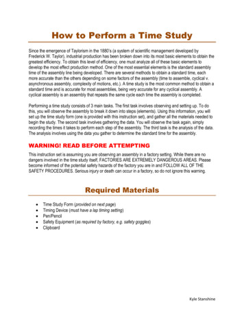
Wiring The SystemThe Ultimate LS kit makes wiring the harness very simple. Every connection in the harness is labeled for where itgoes.The various wires will need to be extended to make required connections. See the wire chart on page 7 which listseach wire used in the system and what it connects to. It is strongly suggested that any wire extensions are made with thesame gauge and color wire as is used in the supplied harness. Make connections as a soldered joint rather than acrimped connection. Utilize a shrink wrapped sleeve covering all connections. All modifications to wiring must be made onharness “A” (the vehicle side wiring) such as extensions or cuts. Any modification of the ECU side harness will result in aVOID of warranty.20112361517221910211213182161461724895834
12WireLocationVSSVehicle speed sensor connects to back of transmission outputPOS (red)3Accessory Wires5Orange wire7Two trans connectors468Red Wire: keyGroundsO2 sensor: driver sideCoil P141516not used if not using transmission controlDRV.0211132 one grounds out ignition and one grounds ECU low currentsecond O2: passenger side: Yellow 6-pin connectorFuse box12Fuel Pump circuit. This wire provides 12V to the fuel pump and connects to thepositive ( ) terminal on the pump. No relay is required.O2 Harness910Main Power: positive 12V goes to starter. This circuit needs to be live even whenthe switch is off so that the self-learning files are saved. This is fused with a 25 ampfuseDashboard odometers bunch: can be taken out of wire sheathing to be relayed todifferent placescranking powerOn/Off - Connect this wire to a switched 12V circuit. Must be on during both "KeyOn" and "Cranking."Coil DK nockInj Pinj DCKPone is fuel pump relay and one is main relaypassenger, ignition coil pack: coils not in kitcoil driver side connects to the universal connector on pre existing coil packsub harness extension to reach to LS3 LS2 on sideLS1 back of blockinjector passenger side harnessinjector Driver side harnesscrank position sensor, in between the block and the starteravailable with extensions for LS3 and LS2 where cam connects to front (not included) LS1 connects to back17CAM: cam sensor19CTS21MAPConnects to the back of the manifoldInstall with the bolt23TPSThrottle Position sensor: on throttle body182022ALTIATIAC24 Hand-held connectionConnects directly to the alternatorThis wire connects to the Engine Coolant Temperature Sensor on the driver sidefront cylinder headIdle air temperature: Connects to the front driver side of the manifoldThread into the manifoldIdle Air Control: Connects on the throttle bodyconnect the two female ends to the hand-held harness male connectors9
VSS: Vehicle speed sensor connects to back of transmission outputPOS (red) Main Power: positive 12 v goes to starter. This circuit needs to be live even when the switch is off so that theself-learning files are saved. This is fused with a 25 amp fuseAccessory Wires :Dashboard odometers bunch: can be taken out of wire sheathing to be relayed to different placesRed wire: key cranking powerOn/Off - Connect this wire to a switched 12V circuit. Must be on during both "Key On" and "Cranking." DO NOT connect tothe coil terminal when using an external CDI box such as an MSD 6A or any other CD ignition.Orange Wire Fuel Pump Circuit: This wire provides 12V to the fuel pump and connects to the positive ( ) terminal onthe pump. No relay is required.Grounds: 2 one grounds out ignition and one grounds ECU low currentTwo trans connectors: not used if not using transmission controlO2 Harness: Yellow 6-pin connector. The second O2 connector goes to the passenger side.Fuse box: one is fuel pump relay and one is main relay10
Coil D: coil driver side connects to the universal connector on pre existing coil packCoil P: passenger, ignition coil pack: coils not in kitK nock: knock sensor: sub harness extension to reach to LS3 LS2 on sideLS1 back of blockInj P: injector passenger side harness11
CKP: crank position sensor, in between the block and the starterCAM: cam sensor: available with extensions for LS3 and LS2 where cam connects to front (not included) LS1 connectsto backALT: Connects directly to the alternatorCTS: This wire connects to the Engine Coolant Temperature Sensor on the driver side front cylinder head12
IAT: Idle air temperature: Connects to the front driver side of the manifold and thread into the manifold. This sensor issupplied and must be inserted in the manifold.A 3/4" hole is required for the sensor.MAP: Connects to the back of the manifold; Install with the boltIAC: Idle Air Control: Co
FiTech Ultimate LS Induction System is designed for street and performance engine applications with a 1500-6500 rpm power-band. The Ultimate LS kits are designed to support either 500 hp or 750 hp to the flywheel and contains a 3 BAR . troller with a data logging feature. The Ultimat