Transcription
user manualGeareducer model M1712 – M1712.5 – M1713 I N STA L L AT I O N - O P E R AT I O N - M A I N T E N A N C EZ1051231ISSUED 04/2017READ AND UNDERSTAND THIS MANUAL PRIOR TO OPERATING OR SERVICING THIS PRODUCT.
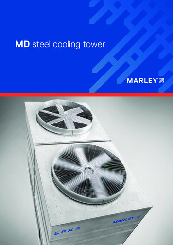
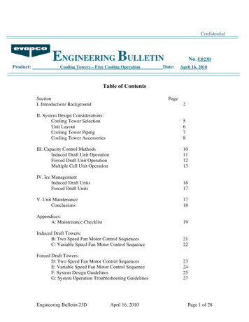
fan hub installationThe following instructions detail the process for installing a fanon a Marley Geareducer with a straight fan shaft using a splittaper bushing or a tapered fan shaft utilizing a bolted fan hubretention plate.1. Remove the retention plate and hardware from the top of theGeareducer shaft. Thoroughly clean the fan shaft, fan shaftkey, and the fan hub center bore to remove any debris and/orprotective coatings. After cleaning, apply a coat of anti-seizecompound to the top 7" (180mm) of the fan shaft.RETENTIONPLATERETENTIONBOLT2. Prior to hub installation, fully seat the key in the fan shaftkeyway. The key is a tight fit across the width and must neverbe altered.3. Raise the fan hub above the fan shaft for installation. Slowlylower the hub onto the shaft with the keyways properly aligned.Make certain the key does not slide down during installation.Stake the key in the keyway with a center punch if necessary.The fan shaft key should be approximately centered in theengaged portion of the hub when engaged on the shaft. Verifythe center hub is fully seated by visual inspection.4. Figure 1 illustrates proper retention plate and hardware installation. The retention plate is designed to allow clearance forthe fan shaft key, and when properly installed will not extendover or interfere with the key in any way. Torque the retentionbolts to 70 ft·lbƒ (95 N·m).2Figure 1 Retention Plate Assembly
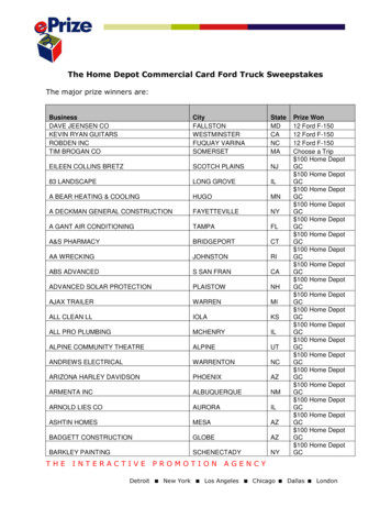
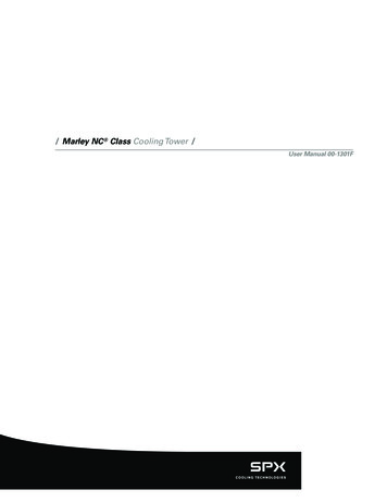
operation and serviceCorrosion and Dry Start-Up ProtectionMarley Geareducers utilize iron and steel materials, which if notmaintained correctly, may degrade. While some external corrosion is acceptable, an internal lubrication film must be maintained at all times to protect the working components againstcorrosion and potential startup damage. The following information describes methods of operation and preventive measuresto ensure suitability for long-term operation.Status DefinitionsAs shipped, a Marley Geareducer is protected internally againstcorrosion with machine enamel on un-machined parts and withrust-proofing oil and grease on machined surfaces. These coatingsnormally protect the Geareducer against corrosion for the durationof the Pre-Commission phase. Adding normal lubricant to theunit will dissolve the rust-proofing oil in the Geareducer sump.Provided it is added via the filler-neck or pumped in through thedrain connection, this lubricant will not reduce the overall levelof protection however, if the unit is operated for any amount oftime, the Pre-Commission period is depleted and the unit is nowconsidered to be in Operational status.Duration* Up to 4 months after receipt.Check the Geareducer exterior yearly. Touch up with paint asrequired. Exposed pipe threads are coated to prevent corrosion.Touch up coating as required.* export shipment status duration is reduced by 1 monthInitial OperationPre-Commission This is the as-shipped condition, which contains a factory rustproofing coating on the interior of the unit as well as a greasecoating on the exposed shaft surfaces. If the cooling tower is not ready for operation at the time ofstatus expiration, steps must be taken to place the Geareducerinto Long-Term Storage or Downtime status.Operational This stage is initiated upon the first motor driven sequence. TheGeareducer is now considered as being placed into regularservice and operation.IdleDuration 2 to 4 weeks. This stage is a suspension in operational status and lasts upto two 2 weeks. The duration may be doubled by completinga Run Cycle. It is not recommended to extend the idle status more than oncein any given sequence.A common application is during a temporary outageSeasonal ShutdownDuration Up to 4 months after operational is suspended.This stage may be considered an extended idle condition.Requires additional preventive maintenance.Long-Term Storage or DowntimeDuration Indefinite.Requires long-term preventive measures.Run Cycle Defined as full speed operation for a minimum of 30 minutes.This recoats all internal components and surfaces with lubricant and also helps to expel some moisture that may haveaccumulated from daily ambient condition cycling.PrimingDue to lack of control over facility operational readiness, siteambient conditions or storage practices, etc., it is recommendedto supplement lubricant prior to initial operation. The same fill lubricant should be poured or pumped into the port above the interstageshaft. Remove pipe plug in center of Interstage Bearing Cap toexpose port. Refer to Figure 3. If additional oil is being used, anamount of 1 to 1.5 quarts should be used. If the lubricant is beingpumped from the sump bulk volume, at least 1 quart should betransferred. In either case, this priming step should be performedwithin 5 days of initial operation. If a delay occurs and the 5 dayduration is exceeded, repeat the process. In either case, this primingstep should be performed while rotating the gear train by handand within 5 days of initial operation.Warning – Operating the Geareducer at an oil level other thanbetween the Add and Full levels may damage the unit and possiblymating equipment. This could also escalate to a safety concernfor nearby personnel.The Geareducer must be filled with oil to the Full oil level mark onthe Geareducer case before it is placed in operation. If the unitis being taken out of Long-Term Storage or Downtime, the oilshould be drained down to the Full operating level. If drain-downoccurs within 5 days of the initial startup, the above priming sequence may be skipped. See Service and Lubrication sectionfor oil filling instructions.Geareducers supplied with new cooling towers include oil for theinitial filling and in some cases, will also ship with an additionalamount required to place the unit into Long-Term Storage orDowntime status. Normally, oil is not furnished with Geareducerssupplied as a spare or on replacement orders. Before operatingthe mechanical equipment, check to be sure the oil level is at theFull mark at the Geareducer and that the external gauge placardFull mark corresponds with the Full level in the Geareducer. Checkoil lines to be sure there are no leaks.3
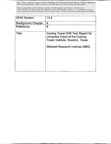
operation and serviceThe Geareducer vent or vent line must be checked for blockageto prevent failure of pinion shaft oil seal—clean when necessary.Every 2 weeks check the oil level and perform a Run Cycle.Once each month drain any water condensation from the lowestpoint of the Geareducer and its oil system. Check the oil level andadd oil if necessary. Perform a Run Cycle.To put back into operation, drain water condensation from thelowest point of the Geareducer and its oil system and check oillevel. Add oil if necessary.Long-Term Storage or Downtime indefinite durationIf unit has been in an operational state, perform a Run Cycleand drain the oil including volume in the oil line, if equipped. If instorage, unit does not need to be operated.Fabricate and install an overflow reservoir system and fill unitentirely full of oil.Maintenance Cycle If unit is stored outdoors, drain condensatemonthly and top off oil as necessary. If unit is stored indoors,but not climate controlled, maintenance cycle may be extendedto 3 months. If stored in climate controlled space, cycle may beextended to once per year.Figure 2 Priming Interstage ShaftCheck all gasketed joints for oil seepage. Tighten cap screws andflange bolting if necessary.The Geareducer must be installed level and properly aligned with thedriveshaft and motor shaft. Refer to the Driveshaft User Manual.It is recommended to operate the Geareducer for no less than30 minutes in any given run sequence. It is acceptable to ignorethis when “bumping” the motor for confirmation of the correctdirection of rotation.Seasonal Shutdown up to 4 monthsInspection Of Internal PartsRemove the inspection cover plate from the side of the Geareducercase at each oil change. Check inside of the Geareducer for cleanliness of case and internal parts. If any sludge is present, flush theinside of the Geareducer and connecting oil line.Service and LubricationAt start of shutdown period, perform a Run Cycle and change theoil. See section on Service and Lubrication.OIL LEVEL CHECKOIL FILL PLUGVENT LINESee Marley User Manual Z0238848 “Cooling Tower DowntimeInstructions” and Marley Drawing Z0544916 “Marley GeareducerReservoir System” for further OUNTINGThe horizontal part of the oil line must be level or slightly lowerat the oil level gauge than at the Geareducer. The oil capacity ofthe M1712 is 17 gallons, the M1713 is 23 gallons. The oil levelgauge line requires approximately one additionalgallon of oil. Referto back cover for suggested lubricants.OIL GAUGEVENTOIL LEVELGAUGEDRAIN PLUGOIL GAUGEAND DRAIN LINEFigure 3 Service Fittings4THREE-WAYVALVE
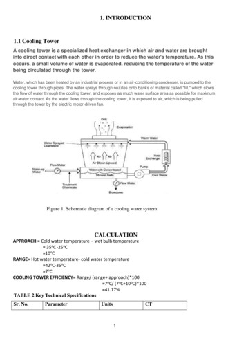
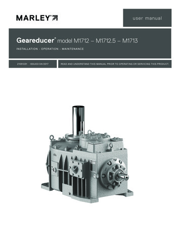
operation and serviceVENTOIL LEVELPLACARDNOTICECHECK OIL LEVEL TENMINUTES AFTERFAN STOPS ROTATINGFULLADDOIL2. Start the fan drive and run for one minute.3. Stop the fan drive. Allow ten minutes for oil level to stabilizeand recheck oil level at the Geareducer.OIL LEVELGAUGE4. If necessary, repeat steps 2 and 3 until stabilized oil level is atthe proper level.FILL AT GEAREDUCERREFER TO SERVICE MANUALFOR OIL CHANGE ANDMAINTENANCE RECOMMENDATIONS5. Check gauge placard location. Full mark on the placard mustbe at the same elevation as the Full mark at the Geareducer.SPX COOLING TECHNOLOGIESOVERLAND PARK, KS USA92-110AAlternate procedure:The cooling tower has an external oil gauge and drain line equippedwith a three-way valve below the oil level gauge. See Figure 3.1. Remove pipe plug. Turn valve control stem clockwise to opendrain.2. With Geareducer drained, the three-way valve turned clockwise,and the pipe plug removed, connect fill source (usually a hoseto a pump, to the three-way valve).Figure 4 Oil Level Gauge AssemblyPump oil through the hose. Check oil level occasionally byturning the valve control stem counterclockwise and allowingthe oil level in the sight glass to stabilize.Fill the Geareducer and oil line system with oil, using one of thefollowing procedures:Recommended procedure:1. Install oil at the opening at the Geareducer inspection coveruntil it reaches the level of the Full mark on the Geareducercase and at the oil level gauge. See Figures 3 and 4. Installplug.Maintenance ServiceMonthlyContinue filling until full level mark is reached.3. With the oil level at the full mark turn the valve control stemcounterclockwise to close the drain and open the valve to thesight glass. Remove the oil filling line and reinstall pipe plug inthe three-way valve.SemiannuallySeasonalStartup orAnnuallyxxGeareducer Drive:Inspect and tighten all fasteners including oil plugCheck for and repair oil leaksxxxCheck oil levelxRxChange oilRRMake sure vent is openxxCheck driveshaft or coupling alignmentxInspect and tighten driveshaft or couplingfastenersxCheck driveshaft or coupling bushing / flexelements for unusual wearxLube Lines (if equipped)Check for oil leaks in hoses and fittingsxRxMaintenance of the Geareducer should be scheduledas follows:Monthly: Check oil level at least once a month usingthe following procedure:Stop the fan drive. Allow ten minutes for oil level tostabilize and check oil level at the gauge. If needed,add oil to Geareducer. If oil is added, repeat steps2 and 3 of recommended procedure until stabilizedoil level is at the proper height.Semi-Annually: Change oil at least every 6 monthsor 3,000 hours of operation. Refer to recommendedoil change procedure.Check the oil level placard location each time theoil is changed. The Full mark on the placard mustbe at the same elevation as the Full arrow on theside of the Geareducer case. See Figures 3 and 4.Oil level gauge vent must be kept open. Inspect ateach oil change and clean when necessary. Inspectinternal parts and inside of Geareducer case at eachoil change—see section on inspection of internal parts.R – Refer to instructions within this manualNote: It is recommended at least weekly, that the general operation and condition be observed. Pay particularattention to any changes in sound or vibration that may signify a need for closer inspection.5
parts list306307305INTERSTAGEBEARING CAP704WATER SLINGER703500LABYRINTH RING500204206AIR VENT202412603422GEAREDUCERCASE COVER3035 – INTERSTAGE BEARINGRETAINERFAN SHAFT301101 – SPIRAL BEVELRING GEAR304302201106201INTERSTAGE SHAFT411INSPECTIONCOVER421203205101 – PINION SHAFT AND GEAR102500105702PINION CAGE401104602GEAREDUCERCASE402103Figure 5 Exploded Assembly6701PINION CAGECAP
parts list1Complete Geareducer Assembly100 Spiral Bevel Gear Set101 Set of matched spiral bevel gears includingintegral pinion shaft with key102 Oil slinger103 Locknuts104 Lockwasher105 Pinion shaft key106 Interstage shaft key108 Ring gear spacer (2.304 and 2.435 gearsets only)200 Helical Gear Set201 Set of matched helical gears includinginterstage shaft and special key202 Top interstage bearing retainer disc203 Bottom interstage bearing retainer disc204 Machine Bolts205 Place bolts and washers206 Washers300 Fan Shaft Assembly302 Key303 Fan hub ring304 Retainer ring305 Fan hub retention plate306 Retention cap screws307 Lock washer400 Pinion Shaft Bearing Set401 Tail, tapered roller bearing402 Head, tapered roller bearing410 Interstage Bearing Set411 Lower, double row, tapered roller bearing.Matched assembly with cone spacer412 Upper, double row, tapered roller bearing.Matched assembly with cup spacer420 Fan Shaft Bearing Set421 Lower tapered roller bearing422 Upper tapered roller bearing500 Shim set501-502-503 Pinion shaft shims504-505-506 Interstage shaft shims507-508-509 Fan shaft shims600 Gasket Set602 Inspection cover gasket603 Oil trough gasket700O-Rings Set.701 Pinion Shaft Oil Seal702 Pinion cage O-ring, 93 4" ID 10″ OD 1 8"703 Water slinger O-ring704 Interstage cap bolt O-ringRepair and OverhaulIf your Geareducer ever needs replacement or repair, SPX CoolingTechnologies recommends returning the unit to a Marley factoryservice center. Contact your Marley sales representative to discussa course of action. A factory reconditioned Geareducer carriesa one year warranty. The Marley Order Number on your coolingtower will be required if the Geareducer is shipped back to thefactory for repair. Obtain a “Customer Return Material” tag fromthe Marley sales representative in you area. To find your Marleysales representative call 913 664 7400 or check the internet atspxcooling.com.7
Geareducer M1712 - M1712.5 – M1713U S E R M A N UA LSuggested LubricantsThe list of lubricants is provided as reference only. These productshave been recommended by their respective manufacturers as acceptable for use in a Marley spiral bevel and/or helical Geareducerfor cooling tower applications. This list is not an attempt to includeall the lubricants that may be satisfactory. If lubricants other thanthose listed are used they must not contain any additives—suchas detergents or EP additives—which are adversely affected bymoisture and could reduce the service life of the Geareducer.Suitability of lubricants used other than those listed rests with thecustomer/owner and lubricant supplier.ManufacturerProductSPX Cooling Technologies Inc.Mineral Turbine ISO 220ChevronRegal R & O 220Citgo Petroleum Corp.Pacemaker 220ConocoPhillipsMultipurpose R & O 220ExxonMobil Corp.DTE Oil BBExxonMobil Corp.Teresstic 220Lubrication Engineers Inc.Monolec 6405ShellMorlina S3 GA 220Synthetic Oil*SPX Cooling Technologies Inc.Gearlube ISO 220ChevronClarity 220 SyntheticCitgo Petroleum Corp.Citgear Synthetic HT 220ConocoPhillipsSyncon R & O 220ExxonMobil Corp.SHC 630ShellMorlina S4 B220*Synthetic oil may be applicable for high temperature serviceor extended oil liveSPX COOLING TECHNOLOGIES, INC.7401 WEST 129 STREETZ1051231 ISSUED 05/2017OVERLAND PARK, KS 66213 USACOPYRIGHT 2017 SPX CORPORATION913 664 7400 spxcooling@spx.comIn the interest of technological progress, all products are subject to designspxcooling.comand/or material change without notice.
See Marley User Manual Z0238848 "Cooling Tower Downtime Instructions" and Marley Drawing Z0544916 "Marley Geareducer Reservoir System" for further information. Inspection Of Internal Parts Remove the inspection cover plate from the side of the Geareducer case at each oil change. Check inside of the Geareducer for cleanli -