Transcription
HDBaseT e M(HDMI Ou
IMPORTANT SAFETY INSTRUCTIONSTo reduce the risk of fire or electric shock, read and follow all instructions and warnings in thismanual. Keep this manual for future reference.1. Do not expose this apparatus to rain or moisture. Do not expose this equipment to drippingor splashing, and ensure that no objects filled with liquids, such as vases, are placed on theequipment. Do not use this apparatus near water.2. Do not remove cover. No user serviceable parts inside. Refer servicing to qualified servicepersonnel.3. Clean only with a dry cloth.4. Do not block any ventilation openings. Install according to manufacturer’s instructions.5. Do not install near any heat sources such as radiators, heat registers, stoves or otherapparatus (including amplifiers) that produce heat.6. Do not override the safety purpose of the polarized or grounding plug. A polarized plug hastwo blades, one of which is wider than the other. A grounding plug has two matching bladesand a third grounding prong. The wide blade or the third prong is provided for your safety. Ifthe provided plug does not fit into your outlet, consult an electrician for replacement of theobsolete outlet.7. Protect the power cord from being walked on or pinched, particularly at the plug end andwhere the power cord is attached to the apparatus.8. Only use attachments and accessories specified by the manufacturer.9. Refer all servicing to qualified service personnel. Servicing is required when the apparatushas been damaged in any way, such as when the power supply cord or plug is damaged,liquid has been spilled on or objects have fallen into the apparatus, the apparatus hasbeen exposed to rain or moisture, the apparatus does not operate normally, or it has beendropped.10. To completely disconnect this equipment from power, disconnect the power supply cordfrom the power outlet.The lightning flash with arrowhead symbol, withinan equilateral triangle, is intended to alert the userto the presence of uninsulated dangerous voltagewithin the product’s enclosure that may be ofsufficient magnitude to constitute a risk of electricshock to persons.The exclamation point within an equilateral triangleis intended to alert the user to the presence ofimportant operating and maintenance (servicing)instructions in the literature accompanying theappliance.2CAUTIONTO REDUCE THE RISK OF ELECTRICALSHOCK:DO NOT REMOVE COVER. NO USERSERVICEABLE PARTS INSIDE.REFER SERVICING TO QUALIFIEDSERVICE PERSONNEL.
CONTENTS1. Product Overview .42. Features.43. Package Contents.44. Device Layout.54.1. B-540-EXT-330-RS-IP Transmitter.54.2. B-540-EXT-330-RS-IP Receiver.65. Installation.65.1. B-540-EXT-330-RS-IP Transmitter Installation.65.2. B-540-EXT-330-RS-IP Receiver Installation.76. Applications . .76.1. HDBaseT Link (RJ45) Connection.86.2. IR Control Connections.86.2.1. Point-to-Point IR Control — Stereo (3.5mm) IR Receiver.96.2.2. Control System — Mono (3.5mm) IR Receiver.96.2.3. IR Flasher Out— Mono (3.5mm).106.3. RS-232 Control Connections.106.3.1. RS-232 Control (DB-9) Connection.116.3.2. RS-232 Operation Mode / Firmware Update Operation.126.4. IP Control Connections.126.5. Thread-Locking Power Supply.137. Specifications.148. Support .159. Warranty.153
1. PRODUCT OVERVIEWWelcome to Binary. This product is engineered to provide years of exceptional reliability. Weappreciate your business and we stand committed to providing our customers with the highestdegree of quality and service in the industry.This device extends HDMI over a single category cable using HDBaseT technology allowingvideo and audio transmission to remote displays. In addition, the device is equipped withbidirectional IR, RS-232, and IP over a single category cable.This unit supports all HDMI defined audio and video formats, including 4K2K@30 Hz andis compatible with HDMI 2.0 and HDCP 2.2 products. The Power over Cable (PoC) featureenables the extender to be powered from either end.2. FEATURES Extends all HDMI formats up to:Resolution1080i/720p 24-bit colorFull HD 1080p 24-bit colorFull HD 1080p 36-bit colorUltra HD 4K2K@30 Hz*Cat 5e/6/6a/7330'330'330'330'*This unit supports HDMI 2.0 and HDCP 2.2 formats Supports all HDMI supported audio formats, including DTS-HD Master and Dolby TrueHD Bidirectional IR, RS-232, and IP PoC capable - can be powered from either the transmitter or receiver3. PACKAGE CONTENTS 1x B-540-EXT-330-RS-IP Transmitter 1x B-540-EXT-330-RS-IP Receiver 1x 12V DC, 2A Power Supply 4x Mounting Ears 4x Mounting Screws 8x Rubber Feet 1x Installation Manual 1x Power Supply Label 2x HDBaseT Labels4
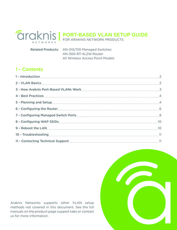
4. DEVICE LAYOUT4.1. B-540-EXT-330-RS-IP TransmitterABCD EFGHI123JK L4ONEthernetBack of TransmitterFront of TransmitterFIGURE 1: Transmitter LayoutA. Thread-locking Power ConnectorConnect to the included 12V DC, 2A power supplyB. Power LEDLights up blue when the unit has powerC. HDMI INHDMI Input to connect to the HDMI output of a sourceD. IR FlasherIR output to connect to IR FlasherE. IR ReceiverIR input to connect to IR Receiver or to output of a control systemF. IR Flasher levelAdjusts the intensity of the IR Flasher outputG. Ethernet (RJ45)To communicate IP data between Transmitter and ReceiverH. DIP SwitchesIR RCVR PWR OFF/ONOFF to connect to control system ON to connect to IR ReceiverDCE/DTETo select if serial (RS232) communication via DB-9 is in DTE or DCE modeLINK/SERVICE DIPLINK for passthrough (normal) operation SERVICE for firmware operationI. RS-232To communicate RS-232 command with the receiver when connected to a control systemJ. HDBaseT (RJ45)To connect to the HDBaseT RJ45 port on receiverK. Link LEDLights up green when synced with receiverL. Update (mini USB port)To connect mini USB cable when updating firmware5
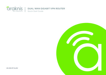
4.2. B-540-EXT-330-RS-IP ReceiverABCD EFGHI1ON2JK3EthernetBack of ReceiverFront of ReceiverFIGURE 2: Receiver LayoutA. Thread-locking Power ConnectorConnect to the included 12V DC, 2A power SupplyB. Power LEDLights up blue when the unit has powerC. HDMI OutHDMI Output which could be connected to the HDMI input of a sink (display)D. IR FlasherIR output to connect to IR FlasherE. IR ReceiverIR input to connect to IR Receiver or to output of a control systemF. IR Flasher levelAdjusts the intensity of the IR Flasher outputG. Ethernet (RJ45)To communicate IP data between Transmitter and ReceiverH. DIP SwitchesIR RCVR PWR OFF/ONOFF to connect to control system ON to connect to IR ReceiverDCE/DTETo select if serial (RS-232) communication via DB-9 is in DCE or DTE modeLINK/SERVICE DIPLINK for passthrough (normal) operation SERVICE for firmware operationI. RS-232To communicate RS-232 command with the transmitter when connected to a controlsystemJ. HDBaseT (RJ45 )To connect to the HDBaseT RJ45 port on transmitterK. Link LEDLights up green when synced with receiver6
5. INSTALLATIONCAUTION: Do not connect power to the device until all other connections are made and theunit is installed.5.1. B-540-EXT-330-RS-IP Transmitter Installation1. Run category cable from the location of the transmitter to the remote location of the receiver.2. Mount the transmitter in the desired location.3. Connect the HDMI Out of a source component using an HDMI cable.4. Connect the RS-232 DB-9 from a control system if being used.5. Connect an IR control system to the IR receiver and/or IR flasher if being used. Refer to Section 6.2.6. Connect the patch cable from the router or network switch to the ethernet port (RJ45).7. Connect the 12V DC, 2A power supply to the latch-locking power jack, unless PoC is beingused to send power from the receiver. DO NOT plug the power supply into an AC outletuntil Receiver Installation is completed.5.2. B-540-EXT-330-RS-IP Receiver Installation1. Run category cable from the location of the transmitter to the remote location of the receiver.2. Mount the receiver in the desired location.3. Connect the category cable to the receiver.4. Connect an IR flasher and/or IR receiver if being used. Refer to Section 6.2.5. Connect an HDMI cable from the HDMI Out of receiver to the display.6. Connect the RS-232 DB9 to an RS-232 controllable source if being used.7. Connect the ethernet RJ45 to an ethernet enabled device if being used.8. Connect the 12V DC, 2A power supply to the latch-locking power jack, unless PoC is beingused to send power from the transmitter.9. Connect the power supply to the AC outlet.7
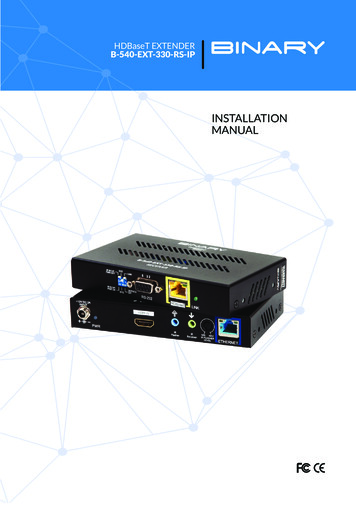
6. APPLICATIONSHDMI SourcePLAYHDMIACPowerB-540-EXT-330-RS- IP tBack HDMIB-540-EXT-330-RS-IP ReceiverFrontFIGURE 3 : Application DiagramNote: When a power supply is connected to either the transmitter or receiver, the HDBaseTlink sends power to the other unit. Only one unit requires a power supply to be connected.6.1. HDBaseT Link (RJ45) ConnectionThis device is specified to operate with category cables for communication between the transmitterand receiver. The transmission path may include a maximum of two keystones and two patch cables,as long as the total length does not exceed 330' for category cable.TIA/EIA Standard 568-B (Gold Pins Facing Up)Pin 1Pin 2Pin 3Pin 4White/OrangeOrangeWhite/GreenBluePin 5Pin 6Pin 7Pin 8White/BlueGreenWhite/BrownBrownFIGURE 4: RJ45 ConnectionsNote: The HDBaseT Link RJ45 connection includes a 12V signal. Do not connect anything tothis port other than an HDBaseT transmitter or receiver.8
6.2. IR Control ConnectionsBidirectional IR signals can be transmitted between transmitter and receiver through categorycable. The IR signal can be generated either from a powered receiver or from a control system.The following section describes these two use cases.CAUTION: Pinout configurations for IR receivers and control systems vary. Before connectingto this input, review this section carefully in order to match the pinouts for the device.HDMI SourceIR Processor/ ControllerPLAYIR InputsIR OutputsB-540-EXT-330-RS-IP Transmitter1234ONEthernetBackC AFrontHDBaseTC B1ON23EthernetBackFrontB-540-EXT-330-RS-IP ReceiverHDTVFIGURE 5: IR ConnectionsNote: Arrow direction indicates signal flow. DIR Receiver In-3.5 mm Mono—See Section 6.2.2IR Receiver In-3.5 mm Stereo—See Section 6.2.1IR Flasher Out-3.5 mm Mono—See Section 6.2.3HDBaseT Link category cable (RJ45)—See Section 6.19D
6.2.1. Point-to-Point IR Control — Stereo (3.5mm) IR ReceiverWhen using a powered IR receiver, the DIP switch for IR RCVR PWR should be set to ON. Inthis case a 3.5mm (1/8") stereo jack has to be used to send 9V DC power to the receiver.CAUTION: DO NOT connect a mono cable to this connection as damage may occur.12314ONONTransmitter23Receiver9V DC (Sleeve)GND (Ring)IR Signal (Tip)Pinout ConfigurationFIGURE 6: Point-to-Point IR settings6.2.2. Control System — Mono (3.5mm) IR ReceiverWhen using a control system which generates the signal through a mono jack, the IR RCVRPWR switch should be in the OFF position.12314ONONTransmitter23ReceiverGND (Sleeve)IR Signal (Tip)Pinout ConfigurationFIGURE 7 : Control System IR settings10
6.2.3. IR Flasher Out— Mono (3.5mm)The IR Flasher level adjusts the intensity of the IR Flasher outputGND (Sleeve)IR Signal (Tip)Pinout ConfigurationFIGURE 8: IR Flasher Out6.3. RS-232 Control ConnectionsBidirectional RS-232 signals are transmitted between the device transmitter and receiver overthe category cable. The transmitter may be connected to a control system and the receiver maybe connected to an RS-232 controllable device.B-540-EXT-330-RS-IP TransmitterA123B-540-EXT-330-RS-IP ReceiverBA41ONONControlSystem23RS-232 ControllableDeviceFIGURE 9: RS-232 Connections RS-232 Control (DB-9)- See Section 6.3.1 HDBaseT Link category - See Section 6.1Front11B
6.3.1. RS-232 Control (DB-9) ConnectionTo eliminate the need to make crossover or null modem cables, the RS-232 pinouts can beconfigured for DCE or DTE. Set switch 2 to DCE if the connected device is DCE, and to DTE ifthe connected device is DTE.Typically the control system will be DTE and the controlled device will be DCE, however,devices may vary. Refer to the manual for the connected devices for proper pinoutconfiguration.DTE ModeDCE ModeTransmitter12341ONReceiver1ONRS-232 DB-9 Pinouts5PIN3 2234ON231ONPINFUNCTION23FUNCTION2RxD (Data Receive)2TxD (Data Transmit)3TxD (Data Transmit)3RxD (Data Receive)5GND5GNDFIGURE 10: RS-232 Modes and Connections6.3.2. RS-232 Operation Mode / Firmware Update OperationThe RS-232 connection can also be used for firmware updates in addition to sending RS-232signals. The DTE/DCE switch is used to set the RS-232 Mode.Note: The SERVICE/LINK switch must set to LINK during normal RS-232 passthroughoperation.To perform firmware updates, the DIP switches must be set to DTE and SERVICE. Detailedinstructions and updated firmware will be posted to www.snapav.com as they are released.Note: The DIP switch should be set to LINK during normal operation.12314ONONTransmitter23ReceiverFIGURE 11: Firmware Update settings12
6.4. IP Control ConnectionsBidirectional Ethernet signals are transmitted between the B-540-EXT-330-RS-IP Transmitterand Receiver over the Cat 5e/6 cable. The most common use is to send Ethernet signals forNetworked TVs or any device in the remote location that has an Ethernet connection. Thisconnection is only to be used for standard Ethernet signals and cannot be used for othercommunication EthernetTransmitterReceiverNetwork Router or SwitchEthernet Enabled DeviceFIGURE 12: IP Control Connection Layout Ethernet (RJ45) HDBaseT Link category - See Section 6.1Note: This connection is for 10/100 BaseT Ethernet ONLY. DO NOT connect a cable from anHDBaseT port.6.5. Thread-Locking Power SupplyThis extender pair is Power over Cable capable and therefore can be powered from eitherthe transmitter or receiver. When a power supply is connected to either the transmitter orreceiver, the HDBaseT link sends power to the other end.CAUTION: Do not connect the power supply to the device until it is completely installedand all connections have been made.13
7. SPECIFICATIONSTechnicalHDMI ComplianceHDCP ComplianceVideo BandwidthHDMI over UTP TransmissionInput TMDS SignalInput DDC SignalESD ProtectionIR Signal (Bidirectional)ConnectionsHDBaseT LinkHDMIIR Receiver (In)IR Flasher (Out)RS-232 passthroughIP pass-throughPowerControlsDIP switch 1DIP switch 2DIP switch 3MechanicalHousingDimensionsWeightPower SupplyPower ConsumptionOperation TemperatureStorage TemperatureRelative HumidityCertifications and ComplianceTransmitterReceiverHDMI 3DYes10.2 Gbps1080i/720p 24-bit color: 330' (Cat 5e/6/6a/7)Full HD 1080p 24-bit color: 330' (Cat 5e/6/6a/7)Full HD 1080p 36-bit color: 330' (Cat 5e/6/6a/7)Ultra HD 4K2K@30 Hz (4:4:4:) 230 ft (Cat 5e/6), 330 ft (Cat 6a/7)Ultra HD 4K2K@60 Hz (4:2:0:) 230 ft (Cat 5e/6), 330 ft (Cat 6a/7)1.2V (peak-to-peak)5V (peak-to-peak, TTL)(1) Human body model: 5kV (air-gap discharge) & 8kV (contactdischarge) (2) Core chipset — 8kVCarrier frequency: 20–60kHz1x RJ451x HDMI Type A(19-pin female)1x RJ451x HDMI Type A(19-pin female)3.5mm Stereo/Mono1x 3.5mmMonoDB-9EthernetLatch-Locking1x 3.5mm Stereo/Mono1x 3.5mm MonoDB-9EthernetIR RCVR PWR OFF/ONRS-232 Pin Configuration (DCE /DTE)RS-232 Operation Mode (SERVICE/LINK)Metal enclosure6.25" x 3.1" x 1.3"1.1 lb12V DC, 2A12W (max)32–104 F-4–140 F20–90% RH (no condensation)Product: CE, FCC, RoHSPower Supply: CE, FCC, RoHS, UL14
8. CONTACTING TECH SUPPORTPhone: 866. 838.5052For SnapAV customers, snapav.comFor Aisle 8 customers, onaisle8.com9. WARRANTY2-Year Limited WarrantyThis Binary Product has a 2-Year limited warranty. This warranty includes parts and laborrepairs on all components found to be defective in material or workmanship under normalconditions of use. This warranty shall not apply to products that have been abused, modified ordisassembled. Products to be repaired under this warranty must be returned to a designatedservice center with prior notification and an assigned return authorization number (RA).15
Rev: 160406-1015 2016 Binary
DCE/DTE To select if serial (RS-232) communication via DB-9 is in DCE or DTE mode LINK/SERVICE DIP LINK for passthrough (normal) operation SERVICE for firmware operation I. RS-232 To communicate RS-232 command with the transmitter when connected to a control system J. HDBaseT (RJ45 ) To co