Transcription
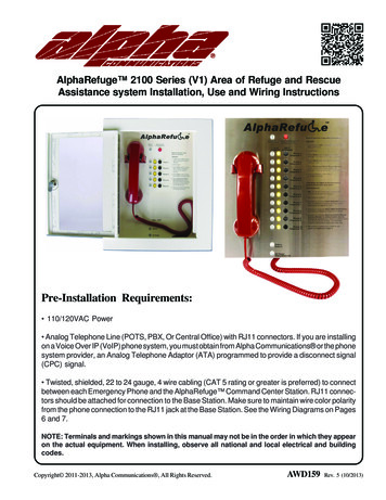
AlphaRefuge 2100 Series (V1) Area of Refuge and RescueAssistance system Installation, Use and Wiring InstructionsPre-Installation Requirements: 110/120VAC Power Analog Telephone Line (POTS, PBX, Or Central Office) with RJ11 connectors. If you are installingon a Voice Over IP (VoIP) phone system, you must obtain from Alpha Communications or the phonesystem provider, an Analog Telephone Adaptor (ATA) programmed to provide a disconnect signal(CPC) signal. Twisted, shielded, 22 to 24 gauge, 4 wire cabling (CAT 5 rating or greater is preferred) to connectbetween each Emergency Phone and the AlphaRefuge Command Center Station. RJ11 connectors should be attached for connection to the Base Station. Make sure to maintain wire color polarityfrom the phone connection to the RJ11 jack at the Base Station. See the Wiring Diagrams on Pages6 and 7.NOTE: Terminals and markings shown in this manual may not be in the order in which they appearon the actual equipment. When installing, observe all national and local electrical and buildingcodes.Copyright 2011-2013, Alpha Communications , All Rights Reserved.AWD159Rev. 5 (10/2013)
Installation: Remove the front cover from the Base Station and punch out conduit knockouts for analog phone lineand Phone cabling runs. Mount Base Station to the wall using suitable mounting screws (not included). Connect the red backup battery cable to the battery terminal. Connect an analog phone line to the RJ11 receptacle located on the lower right of the circuit board (SeeDiagram A below). Attach RJ11 connectors from the phone cabling runs to the appropriate connection on the Base Station.The Phone connections start at the upper right hand side of each circuit board and are numbered on thefront cover. Shield grounds from the cabling runs shouldbe attached to one of the mounting screwson the housing. Mount the front cover on theBase Station. Direct wire to a 120VACsource (see instructionson pages 4 and 5).2
Installation: Connect the hot wire of the 120VAC to the L screw on the power supply Connect the neutral wire of the 120VAC to the N screw on the power supply Connect the ground wire of the 120VAC to the Ground screw on the power supply Connect one lead of the DC power connection to the –V screw and the other to the V screw (polarityis not important) Connect the DC power connection to the AlphaRefuge Control Board. The power connection is onthe lower right hand side of the board3
4
5
6
7
Programming Options for Phone(s):a. To program Emergency Phone(s) in Consolidator mode1. Programming stepsa. Press Enter to get into program modeb. Press 7, Enterc. For Phone(s) 1-5; Press *, 1-5For Example:For Phone 1, Press 7, Enter, *, 1For Phone 2, Press 7, Enter, *, 2d. For Phone(s) 6-10; Press #, 1-5For Example:For Phone 6, Press 7, Enter, #, 6For Phone 7, Press 7, Enter, #, 7e. Press and hold Stop for 2-3 seconds until warble sound to exit programmingf. Confirm operation by calling the phone number Phone(s) are installed on; all phoneswill answer.To speak with individual phone(s): (for phone(s) 1-5 press *1, *2, *3, *4 or *5)or (for phone(s) 6-10 press #1, #2, #3, #4 or #5) to speak with all phones press *0b. To program Phone(s) to call the AlphaRefuge base station unit first and then if no answer to dialsecondary emergency numbers1. Programming stepsa. Press Enter to get into program modeb. Press 1, Enter, 1, Stopc. Press 2, Enter, (Phone Number), Stop (for a secondary emergency phonenumber) press 3-5, Enter, (Phone Number), Stop (for each additional emergencyphone number)d. Press 1, 0, Enter, 4, Stope. Press and hold Stop for 2-3 seconds until warble sound to exit programmingc. To program Phone(s) to dial standard emergency numbers1. Programming stepsa. Press Enter to get into program modeb. Press 1, Enter, (Phone Number), StopPress 2-5, Enter, (Phone Number), Stop (for additional emergency phone numbers)c. Press and hold Stop for 2-3 seconds until warble sound to exit programmingd. To program Location Message1. Programming stepsa. Press Enter to get into program modeb. To turn on message press 1, 3, Enter, 2 or for no message press 1, 3, Enter, 0c. Press 6, Record, (Wait for the Beep, Speak your message), Stop(To replay message press 6, Play)d. To program frequency of message press 1, 3, Enter, (1 plays message once;2 plays message twice (this is the standard configuration); 3 plays message untilcalled party presses * on their phonee. Press and hold Stop for 2-3 seconds until warble sound to exit programming8
Operation:a. Once all connections are made the following LED’s should be lit: Power LED, located on bottom edge of the faceplate, will be constant lit green Battery LED, also located on bottom edge of the faceplate, will be constant lit. Red Low level charge Yellow Mid level charge Green Full Chargeb. Initiate a Call to an Emergency Phone1. Lift handset on AlphaRefuge Base Station2. Press the yellow Talk button corresponding to the Emergency Phone you wish to call into3. The green LED will light next to that button4. You should have two way communication to that Phone5. You can place the Phone on hold the pressing the black Hold button6. To resume communication press the Talk button againc. An Emergency Phone is Activated1. You will hear an alternating audible tone at the Base Station indicating a call has beeninitiated by one of the Phones2. Depending on the Emergency Phone activated, the corresponding green LED, will light onthe Base Station3. The Rescue Services LED, located on the upper edge of the face place, will also be litindicating that the outside line is active4. Lift the handset on the Base Station to join the conversation. If the Phones wereprogrammed to call the Base Station, after you lift the handset you must press the RescueServices button to disconnect the outside line. If the Phones were programmed to dial thestandard numbers, follow the directions listed below5. To talk to Rescue Services only, place the Phone on hold by pressing the correspondingHold button. To bring them back into the conversation, press the Talk button6. To disconnect Rescue Services, press the red button at the top edge of the face plate.The Rescue Services LED will go off and leave you communicating with the Phones only7. If you wish to leave Rescue Services speaking with the Phones, just return the handset to thecradle.9
10
11
12
13
RCB2100SF Flush Mount St. SteelRemote Call Box Station14
15RCB2100SF Flush Mount St. SteelRemote Call Box Station
NOTE: Terminals and markings shown in this manual may not be in the order in which they appearon the actual equipment. When installing, observe all national and local electrical and buildingcodes.ALPHA COMMUNICATIONS 42 Central Drive Farmingdale NY 11735-1202TOLL-FREE TECHNICAL LINE 1-800-666-4800 Phone: 631-777-5500 Fax: 631-777-5599WEBSITE: www.AlphaCommunications.com EMAIL: info@alphacommunications.com16
from the phone connection to the RJ11 jack at the Base Station. See the Wiring Diagrams on Pages 6 and 7. NOTE: Terminals and markings shown in this manual may not be in the order in which they appear on the actual equipment. When installing, obse