Transcription
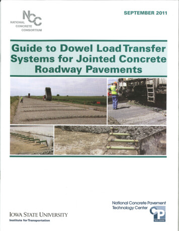
Technical Report Documentation Page1. Report No.2. Government Accession No.4. Title and SubtitleGuide to Dowel Load Transfer Systems for Jointed Concrete Roadway Pavements3. Recipient’s Catalog No.5. Report DateSeptember 20116. Performing Organization Code7. Author(s)Mark B. Snyder8. Performing Organization Report No.9. Performing Organization Name and AddressInstitute for TransportationIowa State University2711 South Loop Drive, Suite 4700Ames, IA 50010-866410. Work Unit No. (TRAIS)12. Sponsoring Organization Name and AddressNational Concrete Consortium2711 S. Loop Drive, Suite 4700Ames, IA 50010-866413. Type of Report and Period Covered11. Contract or Grant No.14. Sponsoring Agency Code15. Supplementary Notes16. AbstractThis guide provides a summary of the factors and design theories that should be considered when designingdowel load transfer systems for concrete pavement systems (including dowel basket design and fabrication) andpresents recommendations for widespread adoption (i.e., standardization). Development of the guide wassponsored by the National Concrete Consortium with the goal of helping practitioners develop and implementdowel load transfer designs based on knowledge about current research and best practices.17. Key WordsConcrete pavement, portland cement concrete, concrete pavement joints18. Distribution StatementNo restrictions.19. Security Classification (of thisreport)Unclassified.21. No. of PagesForm DOT F 1700.7 (8-72)20. Security Classification (of thispage)22. Price36Reproduction of completed page authorizedGUIDE TO DOWEL LOAD TRANSFER SYSTEMS FOR JOINTED CONCRETE ROADWAY PAVEMENTSi
iiGUIDE TO DOWEL LOAD TRANSFER SYSTEMS FOR JOINTED CONCRETE ROADWAY PAVEMENTS
Guide to Dowel Load Transfer Systemsfor Jointed Concrete Roadway PavementsSeptember 2011AuthorMark B. Snyder, Vice-President, American Concrete Pavement Association-Pennsylvania ChapterTechnical Advisory CommitteeMark Brinkman, Construction Materials, Inc.Tom Cackler, National Concrete Pavement Technology CenterGlen Eder, W. G. Block/Dayton SuperiorJenne Impholte-Decker, Simplex Construction SuppliesMaria A. Masten, Minnesota Department of TransportationJohn Staton, Michigan Department of TransportationMatt Zeller, Minnesota Concrete Paving AssociationGUIDE TO DOWEL LOAD TRANSFER SYSTEMS FOR JOINTED CONCRETE ROADWAY PAVEMENTSiii
About This GuideAcknowledgmentsThis guide provides a summary of the factors and designtheories that should be considered when designing dowelload transfer systems for concrete pavement systems (in cluding dowel basket design and fabrication) and presentsrecommendations for widespread adoption (i.e., standard ization).The author would like to thank and acknowledge the con tributions of members of the National Concrete Consortiumwho provided technical input and guidance in the prepara tion and review of this document. In particular, the follow ing people participated on the technical advisory committeeor otherwise provided specific input:Development of the guide was sponsored by the NationalConcrete Consortium (NCC) with the goal of helping practi tioners develop and implement dowel load transfer designsbased on current research and best practices.Mark Brinkman, Construction Materials, Inc.Michael Brinkman, New York State Department ofTransportationTom Cackler, National Concrete PavementTechnology Center, Iowa State UniversityWilliam Cuerdon, New York State Department ofTransportationDoug Dirks, Illinois Department of TransportationGlen Eder, W. G. Block/Dayton SuperiorDarin Hodges, South Dakota Department of TransportationJenne Impholte-Decker, Simplex Construction SuppliesDavid MacDonald, CRSI Epoxy Interest GroupMaria A. Masten, Minnesota Department of TransportationTommy E. Nantung, Indiana Department of HighwaysTom Nicholson, Dayton Superior Corp.Nigel Parkes, PNA Construction TechnologiesJames Parry, Wisconsin Department of TransportationMehdi Parvini, California Department of TransportationJohn Staton, Michigan Department of TransportationSteve Tritsch, CMC AmericasMatt Zeller, Minnesota Concrete Paving AssociationThe NCC is a national forum for concrete pavement researchand technology transfer initiatives. Its projects are supportedthrough the Technology Transfer Concrete Consortium(Federal Highway Administration Pooled Fund TPF-5[159]),and its administrative and publications support services areprovided by the National Concrete Pavement TechnologyCenter at Iowa State University.The overall goals of the NCC are to identify needed researchprojects, develop pooled fund initiatives, provide a forumfor technology exchange between participants, communicatestate agencies’ research needs to FHWA and industry, andprovide implementation assistance to the National ConcretePavement Road Map.NCC participating states include Alabama, California, Geor gia, Iowa, Illinois, Indiana, Kansas, Louisiana, Michigan,Minnesota, Missouri, North Carolina, North Dakota, NewYork, Ohio, Oklahoma, Pennsylvania, South Dakota, Texas,and Wisconsin.It is also important to acknowledge the contributions of all ofthe engineers and researchers over the years—from StephenTimoshenko in the 1920s to Lev Khazanovich and other cur rent researchers—whose works are briefly described and arethe basis for the recommendations made in this guide.Finally, it must be noted that the preparation and publicationof this guide would not have been accomplished without thesupport of the staff of the National Concrete Pavement Tech nology Center at Iowa State University, especially the tirelessediting efforts of Sabrina Shields.For More InformationFor technical assistance regarding concrete pavements, contact theNational Concrete Pavement Technology Center:Tom Cackler, DirectorSabrina Shields-Cook, Managing EditorNational Concrete Pavement Technology CenterInstitute for TransportationIowa State University Research Park2711 S. Loop Drive, Suite 4700Ames, IA chcenter.org/ivDisclaimersNeither Iowa State University nor this document’s authors, editors,designers, illustrators, distributors, or technical advisors make anyrepresentations or warranties, expressed or implied, as to the accuracyof information herein and disclaim liability for any inaccuracies.Iowa State University does not discriminate on the basis of race, color,age, religion, national origin, sexual orientation, gender identity, sex,marital status, disability, genetic testing, or status as a U.S. veteran.Inquiries can be directed to the Director of Equal Opportunity andDiversity, Iowa State University, 3680 Beardshear Hall, 515-294-7612.GUIDE TO DOWEL LOAD TRANSFER SYSTEMS FOR JOINTED CONCRETE ROADWAY PAVEMENTS
ContentsList of Figures . viiList of Tables .viiiIntroduction .1Dowel Load Transfer System Design: A Brief History .1Dowel Load Transfer System Designs and Design Considerations .2Dowel Diameter/Cross-Section .2Dowel Bar Length .3Dowel Alignment Requirements .4Vertical Translation .5Longitudinal Translation .5Dowel Spacing and Number of Dowels .6Epoxy Coatings.6Alternate Dowel Materials and Coatings.7Stainless Steel.8Microcomposite Steel .8Zinc Alloy-Sleeved Dowels.9Fiber-Reinforced Polymer (FRP) and Glass Fiber-Reinforced Polymer (GFRP)Composite Dowels .10Dowel Bar Lubrication/Bond-Breaker Materials .10Use of Expansion Caps and Joint Forming Materials .11Recommendations .11Dowel Bar Material .11Dowel Bar Diameter .11Dowel Bar Length .11Dowel Corrosion Protection .12Dowel Basket Height.12Recommendations for Standardized Basket Frame Design .13Basket Stake Requirements and Other Anchoring Approaches .14Cutting Tie or Spacer Wires Prior to Paving .14Use of Bond-Breakers and Basket Pre-Coating .14GUIDE TO DOWEL LOAD TRANSFER SYSTEMS FOR JOINTED CONCRETE ROADWAY PAVEMENTSv
References .14Additional Resources .15Appendix A - The Mechanics of Joint Faulting .16Appendix B - Design Factors Affecting Dowel-Concrete Bearing Stress (and Faulting) .18Appendix C - Use of FWD Measurements in Measuring Dowel Effectiveness .20Appendix D - Evaluating Dowel Load Transfer Systems .22Appendix E - Concepts for Optimizing Dowel Load Transfer System Design .24Appendix F - Summary of Studies Concerning Use of FRP Dowels in PCC Pavements .27viGUIDE TO DOWEL LOAD TRANSFER SYSTEMS FOR JOINTED CONCRETE ROADWAY PAVEMENTS
List of FiguresFigure 1a. Typical dowel basket assembly . 1Figure 1b. Dowel baskets positioned ahead of paver . 1Figure 2. Load transfer versus dowel embedment (observed and computed) . 4Figure 3. Effects of dowel embedment and diameter on dowel loosenessafter 600,000 repetitions of a 10,000 lb load. 4Figure 4. Photo of retrofit dowel bar assemblies, ready for repair material . 4Figure 5. Photo of epoxy-coated dowel bars in full-depth concrete pavement repair . 4Figure 6. Effect of concrete cover on dowel-concrete shear capacity for 1.25 in. and 1.5 in. dowels,based on both laboratory tests and finite element analyses . 5Figure 7. Effect of concrete cover on LTE for retrofit 1.5 in. steel dowels in 7.5 in. concrete slabs . 5Figure 8. Effect of embedment length on shear force and displacement for 1.25 in. diameter steel dowels. . 6Figure 9. Shear capacity versus embedment length for 1.5 in. diameter steel dowels. . 6Figure 10. Epoxy-coated dowels for retrofit application . 7Figure 11. Corroded (and non-corroded) dowels at in-service pavement joint . 7Figure 12. Various stainless steel dowel products . 8Figure 13. MMFX 2 (microcomposite steel) dowel after five years of service . 9Figure 14. Zinc alloy-sleeved dowel, as manufactured and after five weeks in sodium chloride bathwith a 1 in. wide breach in the zinc . 9Figure 15. Experimental installation of FRP dowels in West Virginia . 10Figure A1. Illustration of pumping mechanism in jointed concrete pavement . 16Figure A2. Joint faulting and corner breaks . 16Figure B1. Sample computation of individual dowel shear loads within a dowel group . 18Figure C1. Placement of FWD load plate and first sensor on opposite sides of atransverse joint for the evaluation of LTE . 20Figure C2. Example of the relationship between deflection and stress load transferefficiencies for a particular pavement design thickness and support condition . 21Figure E1. Screen capture of the dowel sizing module in DowelCAD 2.0 . 26Figure E2. Screen capture of the dowel spacing module in DowelCAD 2.0 . 26Figure F1. Lab test LTE histories for several dowel materials and diameters(7.5 in. PCC slab, 12 in. dowel spacing) . 28Figure F2. Differential deflection (loaded side of joint minus unloaded side of joint)for several dowel materials and diameters (7.5 in. PCC slab, 12 in. dowel spacing) . 28GUIDE TO DOWEL LOAD TRANSFER SYSTEMS FOR JOINTED CONCRETE ROADWAY PAVEMENTSvii
List of TablesTable 1. State highway agency practices for dowel bar diameter (inches) by pavement thickness . 2Table 2. Sample dowel bar pullout test results . 10Table 3. Recommended standard basket heights for various round dowel diameters. 13Table F1. Sample sensitivity analysis of dowel deflection and bearing stress to dowel diameterand material (computed using Friberg’s bearing stress analysis) . 27viiiGUIDE TO DOWEL LOAD TRANSFER SYSTEMS FOR JOINTED CONCRETE ROADWAY PAVEMENTS
IntroductionRound steel dowels are the devices most commonly used fortransferring loads across transverse joints in concrete high way pavements. In new pavement construction, dowels areoften installed in wire basket assemblies that are intended tosupport and hold dowels in the desired position during pav ing operations. These baskets are generally pre-assembled,shipped to the project site, and anchored to the grade beforethe paver places the concrete (Figure 1).State highway agency requirements for dowel baskets varywidely, even though the mechanics of dowel behavior andbasket structural requirements are well-understood. Theadoption of a standard set of dowel basket designs willreduce manufacturer set-up and production costs associatedwith producing many nonstandard designs, and will allowmanufacturers to more easily maintain a larger inventoryof fewer varieties of assembled dowel baskets. These manu facturing process changes should result in lower costs andimproved dowel basket availability (i.e., fewer, if any, pro duction delays) to highway agencies.Figure 1a. Typical dowel basket assemblyThis reference guide provides a summary of the factors anddesign theories that should be considered in dowel loadtransfer system design (including dowel basket design andfabrication) and presents recommendations for widespreadadoption (i.e., standardization).Dowel Load Transfer SystemDesign: A Brief HistoryThe potential benefits of using smooth, round steel barsacross transverse joints as load transfer devices has beenrecognized for nearly 100 years. The first reported U.S. in stallation took place in the winter of 1917–1918 between twoarmy camps near Newport News, Virginia, where four 3/4in. diameter bars were used across the 20 ft pavement widthwith 2 dowels per 10 ft travel lane (Teller and Cashell 1958).The use of steel pavement dowels spread rapidly in theUnited States in the years following World War I and, by1930, nearly half of all states required their use. However,details concerning dowel diameter, length, and spacingvaried considerably. In 1926, for example, one state requiredtwo 1/2 in. diameter bars, 4 ft long; another required four 5/8in. diameter bars (also 4 ft long); and still another requiredeight 3/4 in. bars, 2 ft long.In the following years, numerous dowel bar studies and testswere conducted by Westergaard (1928 and 1938), Bradbury(1932), Teller and Sutherland (1935, 1936, and 1943), and oth ers, with the results leading to the use of dowels that wereincreasingly stiff (larger diameter),
The NCC is a national forum for concrete pavement research and technology transfer initiatives. Its projects are supported through the Technology Transfer Concrete Consortium (Federal Highway Administration Pooled Fund TPF-5[159]), and its administrative and publications support services are provided by the National Concrete Pavement TechnologyCited by: 6Publish Year: 2011
