Transcription
CCTV VIDEOTRAINING MANUALSomeone once said, "Knowledge is the key to success". This rule also appliesto the installation and maintenance of CCTV camera equipment. Have you everinstalled a CCTV camera system and then had to go back to solve a problem thatwas overlooked. A basic understanding of CCTV video signals, can save youhundreds of man hours, improve customer relations and increase job profitability allat the same time. This manual will discuss problems and solutions for CCTV camerainstallations.
Table of ContentsVIDEO LEVELS.1HOW SYNC PULSE AMPLITUDE EFFECTS CCTV INSTALLATIONS.1WHITE LEVEL IRIS SETTING, HOW MUCH IS ENOUGH?1-2PEAK TO PEAK MEASUREMENT OF VIDEO.2COLOR CAMERAS AND COLOR BURST.2VERTICAL INTERVAL, ITS MANY USES.2TERMINATION, THE END OF THE LINE.2-3THE BASIC THREE.3CCTV VIDEO GROUND LOOP PROBLEMS.3-5CCTV FOCUS PROBLEM SOLVING.5DEPTH OF FIELD, WHAT IS IT?6THE PROBLEM WITH AUTO IRIS LENSES.6-7HOW TO SHOOT A LICENSE PLATE WITH A CCTV CAMERA.8-9HOW TO MEASURE CCTV CAMERA OUTPUT IMPEDANCE.10PROBLEMS CAUSED BY INCORRECT TERMINATIONS.10CORRECT MEASURING OF CAMERA OUTPUT IMPEDANCE.11SYNC PULSE PASS / FAIL TEST TABLE 1.11CALCULATION OF PRECISE SOURCE IMPEDANCE.11DIGITAL VIDEO RECORDER PROBLEM SOLVING.12HEADROOM IN THE DVR.12-13HOW TO PREVENT LIGHTNING DAMAGE IN CCTV.14-16CCTV LINE-LOCK PROBLEMS.16-18CCTV UPS TROUBLE SHOOTING TIPS.19-20GROUND LOOPS AND THE COMMON POWER SUPPLY.20-21VIDEO LINES OF DEFINITION.21-25FIBER TRANSMISSION PROBLEM SOLVING.25-28A HELPING HAND.28
VIDEO LEVELS.To discuss video let's start with the unit of measure, the I.R.E. unit. I.R.E.stands for Institute of Radio Engineers, this regulating body set the standards ofmeasure for the video industry. This standard has been adopted by all industries inthe United States and other parts of the world. 140 I.R.E. units is equal to 1 VoltPeak to Peak. I.R.E. units are easier to use because they divide into a video signalevenly.For example proper Sync on a camera is 40 I.R.E. units, the Voltageequivalent would be 0.2857143 Volts. Unfortunately this voltage cannot bemeasured on the Volt Ohm Milliamp Meter that you use for checking contacts. Anoscilloscope has been used by some people for this purpose, but it is bulky anddoes not read in I.R.E. Most people would rather use the simple 40 I.R.E. units ofmeasure. Fortunately some equipment manufacturers sell hand-held batteryoperated meters to measure the video signal in I.R.E. units. This equipment iscompact, extremely accurate and simple to use. Some units like the "CAMERAMASTER" can even help to set the focus of a camera more accurately.HOW SYNC PULSE AMPLITUDE EFFECTS CCTV INSTALLATIONS.A CCTV video camera creates synchronization pulses to lock the viewingmonitor on the picture. These pulses occur at a rate of 15,750 times a second.There is one synchronization pulse or (sync pulse) for each line in the picture frame.The sync pulse tells the video monitor to start drawing a video line across the picturescreen. When it gets to the end of the screen another sync pulse begins the nextline, and so forth until the screen has been filled with lines. It takes 262 and a halflines to form a frame, and two frames to form the video picture we see on themonitor.The proper level for sync is 40 I.R.E. units. If the sync signal from the camerais too small in amplitude the picture will break up or roll. If the sync pulse is too big,any black portion of the picture will be more gray and the dynamic range of thepicture will be degraded. Peak white level will also be compressed causing ablooming effect (loss of picture definition).WHITE LEVEL IRIS SETTING, HOW MUCH IS ENOUGH?There is a standard for Iris setting, or white level and it is 100 I.R.E. units.When setting a manual iris, or an automatic iris the level should be the same, 100I.R.E. units. If you set the iris below 100 I.R.E. units, the picture will be dim with lessthan desired dynamic range and the white picture elements will not be pure white.CCTV TRAINING MANUALPAGE 1 OF 28
If you set the iris for more than 100 I.R.E. units, the picture can be washed outcausing loss of picture definition. Some cameras can be set to 120 I.R.E. units, but itshould be noted that the standard is 100 I.R.E. units and in any case all cameras inthe system should be set to the same level of white. This will ensure that the whiteportion of the picture will be the same brightness when a monitor is switchedbetween them.PEAK TO PEAK MEASUREMENT OF VIDEO.A quick measurement of the peak to peak video signal will re-assure you thatthe CCTV camera is putting out the right level. The standard level is 140 I.R.E. units.COLOR CAMERAS AND COLOR BURST.More color cameras are being used in CCTV installations. The color cameraadds a chromanance component (color information) to the signal, also known asChroma. This Chroma signal operates at 3.58 Mega-Hertz. The standard level forthe Chroma is 40 I.R.E. units. When the chroma level is low, the colors will be dull. Ifthis level is too low, the color monitor will turn its color receiver off causing a Blackand White only picture. This condition also indicates a loss of picture detail. You cansee this effect on long cable runs. The solution is to install a video equalizer in theline and adjust the color burst back to 40 I.R.E. units. If the Chroma signal is too highthe picture will display color flaring and reduction of detail at the edge of the colorflare.VERTICAL INTERVAL, ITS MANY USES.The Vertical Interval (V.I.) is the part of the video signal that tells the monitor tostart drawing a new screen. It is made up of special SYNC pulses with no pictureelements. The standard level for these SYNC pulses are 40 I.R.E. units. All videoSYNC pulses should be 40 I.R.E. units. The Vertical Interval is a very useful place toput alarm and control signals. Some manufacturers make equipment for pan and tiltcamera control, alarm contact information, and data transmission that is inserted intothe V.I. signal and sent up or down the cable.TERMINATION, THE END OF THE LINE.A termination for video is a 75 Ohm resistor placed at the end of any videocable to prevent signal reflections that cause ghosting or multiple images on themonitor. Some CCTV equipment have built-in terminations some of which are switchable. If you are using this equipment in series, you must switch off all Terminationsexcept the termination at the last piece of equipment in the cable run.CCTV TRAINING MANUALPAGE 2 OF 28
Proper termination can be checked by measuring the SYNC pulse amplitudeanywhere in the video cable. It should read 40 I.R.E. with the termination ON, and80 I.R.E. with the termination OFF. If the SYNC level does not change when youremove the termination, the camera or video source is not standard 75 Ohms andshould be serviced or replaced. Problems with V.I. control systems can result if thelevel does not double when you remove the termination.THE BASIC THREE.To check performance of any CCTV camera installation make sure the SYNClevel is 40 I.R.E. units /- 5 I.R.E. WHITE level should be 100 I.R.E. units /- 5I.R.E. Remember if you want to run high white level say 120 I.R.E., be sure that allcamera's in the system have the same level of I.R.E /- 5 I.R.E. Color burst levelshould be 40 I.R.E. units /- 5 I.R.E. SYNC, WHITE, and COLOR BURST are thethree basic measurements to make to insure proper operation of your CCTVsystem.CCTV VIDEO GROUND LOOP PROBLEMS.When Video Ground Loop problems or 60 cycle Bars occur, they are easy tosee on a video monitor. They look like a horizontal band or bar across the videomonitor that slowly moves up the video screen. These bars can be barelynoticeable, or can be so bad that the video monitor loses lock and breaks up thepicture. If the video camera is Line-Locked to the 60 cycle main power, the bars maystand still in the picture, but they still obscure picture definition and create customercomplaints.The source of the 60 cycle bar originates from the power industries use oflocal grounds to balance their power grid. Everywhere 60 cycle power is used, alocal ground is attached to the power grid to return all unbalanced current flow toground. As an example, you will notice that every main power breaker box will havea ground wire or conduit going to a ground rod or similar device connected to anearth ground. Every correctly installed power outlet will have a connection to thisground.Not all grounds are created equal. In fact the earth ground in one building ismost likely to have a different voltage potential relative to any other building, evengrounds inside the same building will have different voltages between them, basedon the uneven current flow of the power load.CCTV TRAINING MANUALPAGE 3 OF 28
Here is how the 60 cycle bar gets into your video picture. If you connect acoaxial cable to a monitor or other equipment that plugs into the 60 cycle mainpower and the other end of the coaxial cable becomes grounded locally for anyreason a Ground Loop is created. Any difference in the 60 cycle voltage betweenthese two ground points will create a current flow in the shield of the coax thatinduces the 60 cycle AC voltage into your video signal.It is easy to measure these differential voltages, simply disconnect the videocables at the monitor point and using your voltmeter on AC volts, measure betweenany two shields of the incoming video cables, you will be amazed at the difference.The solution is to never connect both ends of a video cable to local grounds.Any cable can be grounded at one end without inducing the ground loop current.When you run coax cable from one building to another, it is acceptable to installthrough connection points, but do not allow the shields to come into contact with oneanother or the local ground. A coaxial connector laying in a cable tray or conduit boxcan accidentally contact ground, don't let this happen. Use tape on the connector toprevent accidental grounding. Also try not to attach the camera to any structure thatis likely to be grounded. Remember that the camera is already grounded at theopposite end of the coaxial cable by the monitor equipment.At the monitor station you may have many pieces of equipment connectedtogether, like a (Quad, Tape Recorder, Monitor) all of which plug into the main 60cycle power. This will not present a problem if you plug all of the equipment into thesame power line at the monitor point. Making sure that all the equipment share thesame ground point at the monitor station. Also try to keep the video cables betweenequipment, (the service loops) as short as possible.If you already have an installation that has 60 cycle bars, there are some stepsyou can take to solve the problem. If coaxial cable shields are connected togetheranywhere in the system, separate them if possible. Similarly remove all but oneground connection on each coaxial cable if possible. The ground is usually at themonitor end of the coaxial cable because the monitor equipment plugs into the 60cycle main power supply which is grounded.Sometimes a ground loop problem can be reduced by reversing the AC plugon the power transformer used to power the camera, or reverse the 24 VAC powerconnection to the camera. This technique will not work on DC powered cameras.If the problem still persists, video isolation transformers can be installed at oneend of the coaxial cable to block the shield current flow and eliminate the 60 cyclebars.CCTV TRAINING MANUALPAGE 4 OF 28
These transformers must be installed at the coaxial cable that is originating the60 cycle bar problem. Isolation transformers only work when they can block thecurrent flow in the shield. Once 60 cycle bars become part of the video signal, noeconomical down stream solution will remove the bars. Use a portable monitor tofind the origin of the ground loop problem, start at the camera and move down thecoaxial cable until you see the bars appear on the portable monitor. This then is thecoaxial cable with the current in the shield. Clear the ground connection or install anisolation transformer at this point.The type of AC power transformers you use to power your cameras cancontribute to Ground Loop problems. A ground can be introduced to your camera"Capacitively" through the power transformer windings depending on the type andconstruction technique used to build the AC transformer. Some transformers arebuilt by winding a primary (the 110 VAC side) on a metal core, then simply windingthe secondary coil (24VAC) directly over the primary coil. This puts the primary andthe secondary in direct capacitive contact. This type can cause Ground Loopproblems.Other manufacturers build their AC transformers with a split bobbin. That iseach winding is separately mounted on the metal core. The separation of primaryand secondary coils are greatly increased, reducing the capacitive coupling andremoving the unwanted second ground in your system. This type of transformerusually does not cost any more, and may prevent the 60 cycle ground loop fromoccurring. It would help if you determine which transformers are built to minimizecapacitive coupling between windings and purchase that type only.With an understanding of Ground Loop problems and the use of good singleended grounding techniques, you should be able to keep the 60 cycle bars out ofyour CCTV installations.CCTV FOCUS PROBLEM SOLVING.Have you ever wondered why Auto Iris cameras seem to go out of focus atnight? Many installers have had to return to the job site at night and reset the focusof a camera to solve this problem. This can be costly to your company's pocket bookand reputation. There is a solution to the problem that will enable you to set thecameras focus correctly every time, day or night.Let's examine what causes the Auto Iris camera to go out of focus when thelighting level changes, as it does day to night. All lenses and Auto Iris camerasexhibit this effect to a greater or lesser degree.CCTV TRAINING MANUALPAGE 5 OF 28
DEPTH OF FIELD, WHAT IS IT?All lenses have a characteristic called Depth of Field. Depth of Field is a zonein front of the lens that is in focus. It is measured as the minimum distance andmaximum distance from the lens where objects are in focus. All objects inside thisminimum and maximum bracket zone will be in focus. The further away you go fromthis bracketed "in focus zone", either toward or away from the camera the more outof focus the objects become.THE PROBLEM WITH AUTO IRIS LENSES.The Auto Iris lens has a movable aperture inside the lens that controls theamount of light allowed to pass through it. This aperture also directly controls theDepth of Field of the lens. So an Auto Iris lens will have a variable Depth of Fielddepending on the amount of light entering the lens. This causes the minimum andmaximum bracket zone of focus to change when the lighting level changes.During the day or in bright lighting conditions the Iris is closed down to a smallopening, and the Depth of Field is quite large. So called Pin Hole cameras exhibitthis effect where all objects in the scene are in focus. However with movable iriscameras at night or in low lighting conditions the Iris is open wide, this causes theDepth of Field to collapse down to a smaller minimum and maximum bracketedzone of focus. An object that was inside the zone of focus during the day can beoutside the zone of focus at night.THE SOLUTION.One way to set up the camera to minimize the Depth of Field problem, is toadjust cameras focus at a time when the light level is at its lowest. This may not beconvenient for your installers.The best way is to use a SHADE 5 FILTER PLATE also called a #5 weldersglass filter. It is the filter plate that welders look through to protect their eyes duringwelding operations. When you have full daylight or bright lighting conditions the filterplate is placed over the cameras lens to simulate half lighting conditions.This filter plate costs only a few dollars and should be carried by installationpersonnel to every job site for use with Auto Iris lenses, especially those jobs usingoutdoor cameras. By using the filter plate to adjust the Auto Iris, you will be centeringthe control range of the Auto Iris system. This will give you optimum performancefrom your cameras Iris control system.CCTV TRAINING MANUALPAGE 6 OF 28
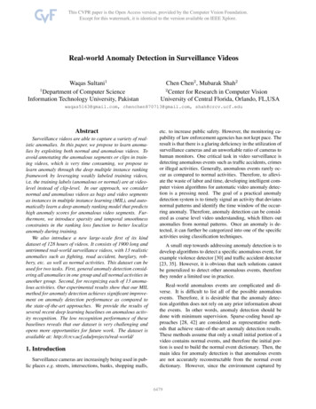
Hand held focus meters such as the CM-2 Camera Master are also useful indetermining the maximum focus of any scene. They are more accurate than largescreen monitors and much easier to take up a ladder. They display the maximumfocus numerically on an LCD type display. By eliminating the subjective nature offocus setting, you will insure that all cameras will be set to their maximum focus byany installer.An understanding of Depth of Field and the proper setting requirements forAuto Iris cameras will save you time and reduce the frustration of having to return tothe job site to refocus cameras.CM-2THIS METER WILL MEASURE VIDEO I.R.E. UNITS AND ALOT MORE!CCTV TRAINING MANUALPAGE 7 OF 28
HOW TO SHOOT A LICENSE PLATE WITH A CCTV CAMERA.When your customer asks you to set up a camera to grab a shot of a licenseplate on a car, here are a few things you will want to know.WHERE TO LOOK.When setting up a camera to view a license plate, the framing is veryimportant. You must frame the camera so that the plate will be in the camera’sview no matter where the plate is mounted on the car, or how the car is positionedin the roadway. The first trick is make sure you place the camera so that it canclearly see the numbers and letters on the license plate. Be sure to set the camerafocus control for the sharpest focus. Make sure the plate is large enough in thescene to be identified. If you can do a good job of this, most installations will workvery well during the daylight.The camera works well during the day because the light from the sun isstrong and defused, it comes from many sources by reflections off of all theobjects in the immediate area.THE PROBLEM.Unfortunately an unaided camera does not do as good a job of readinglicense plates at night. They need some assistance to work well under darkcircumstances. Even if the scene were well lit for observation by eye, a carpresents special problems for a video camera.Often area illumination will be placed immediately over the entrance and exitgates, a narrowing point just where you would like to see the license plate. Just asthe car enters the gate area, a reflection from the overhead light bounces off thewindshield and blinds the camera. The most common sources of camera blindinglight are the headlights on the car. Any direct light source pointing into the cameralens at night will cause a camera blinding effect.The camera blinding effect at the least will result in a loss of detail aroundthe direct light source, like a blooming effect or halo. At its worst it can darken thescreen so that you will only see the two headlights and everything else on themonitor will be black and unreadable.THE CAUSE.The blooming effect or halo type of loss is caused by the scattering ofelectrons on the CCD element inside the camera.CCTV TRAINING MANUALPAGE 8 OF 28
This darkening effect is caused by the auto iris in the camera. When it seesthe bright hot refection or headlights, the iris in the camera will close down theopening in the lens. An auto-iris takes the light that it sees and tries to determinehow to set the opening in the lens for the best picture illumination. It can use apeek measure of the light level entering the lens, or when you engage the “BackLight” feature it will take an average of the light ignoring the hot spots.Unfortunately the back light feature in most cameras will not handle headlights orwindshield flashes and only reduce the problem somewhat.A CLUE.A clue to the answer comes from the relatively good observations madeduring daylight. During the day most of a cameras received light comes fromdefused light and even if a car has its headlights on the camera hardly notices it,because the energy from the headlights are just a small portion of the lightentering the lens.HOW TO MAKE IT WORK.To reduce the blinding effect of reflected light sources you can install a lightsource pointing directly at the car from the direction of the camera to where youwish to read the license plate. The light source must be bright enough tooverwhelm the headlights on the car and stop the cameras auto iris from closingdown due to the increase in direct light. To avoid blinding the driver of the car, youmust use an infra red light source. People cannot see light in the infra redspectrum, but cameras can. In fact most CCTV cameras are very sensitive to theinfra red light spectrum and will work quite well. Infra red light sources areavailable from the same manufacturers that you buy your cameras from.Try a test the next time you have a license plate reading camera. Arrangethe camera in the normal way, and see what happens when the cars lights areturned on. Notice the darkening of the picture on your monitor. Then point aregular bright white spot light at the car from the direction of the camera. Noticethat the scene gets brighter but also the headlights have less of an effect on theiris of the camera and you can see more of the details of the car, with much lessblinding effect.The main point here it to overwhelm the direct light coming from the car witha source of light coming from the camera. If you do this, license plates can beseen easily even under the worst conditions.CCTV TRAINING MANUALPAGE 9 OF 28
HOW TO MEASURE CCTV CAMERA OUTPUT IMPEDANCE.The vast majority of coaxial cables are either 50 Ohm or 75 OhmCharacteristic Impedance. This Characteristic Impedance is determined by the ratioof the diameters of the shield and core wire and the Dielectric Constant of theinsulating material between the core wire and the shield. The CCTV Industry choseto use the 75 Ohm standard for coaxial cable.Since a coaxial cable must be terminated at both ends of the cable withresistances equal to the cable Characteristic Impedance to prevent reflections fromimpairing the picture, cameras must have an internal source impedance of 75Ohms, and Monitors must be provided with a 75 Ohm termination.THE PROBLEM.In the past, CCTV cameras could be counted on to have proper 75 Ohmsource impedances, but recently there have been a rash of cameras showing up onthe market that do not have a 75 Ohm source impedance. In fact they exhibit almostzero output impedance even though the specification sheets that come with themspecify 75 ohms! Clearly the cameras do not meet their own specifications and thuscould be returned for not meeting their own published specifications.PROBLEMS CAUSED BY INCORRECT TERMINATIONS.The worst of termination problems occur when the camera has a zero sourceimpedance, or the 75 Ohm impedance is left off at the Monitor location. By far theworst effects occur when both zero Ohm source impedance exists and the 75 Ohmtermination is removed at the Monitor.Ghosts and Ringing become more evident as the length of the coaxial cablebecomes greater. The ringing effect (where a white-to-black or black-to-whitetransition in the picture is repeated many times in close succession) occurs withshort cable runs of 50 to 200 feet. Obvious Ghosts appear when the cable is 5001000 feet long. The first of many successive Ghosts will be about 1/2 inch to theright of the original object on a TV monitor screen with about 1000 feet of cable.Another problem caused by zero source impedance cameras is that signalsplaced on the coaxial cable to control Pan and Tilt of the camera will be shorted outby the zero Ohm output of the camera and may cause remote Pan and Tilt systemsto be intermittent or fail.The same intermittent or failed condition may be induced into other equipmentthat is using the same coaxial cable to transmit special signals.CCTV TRAINING MANUALPAGE 10 OF 28
The key idea here is that such intermittent or failed conditions are caused by aCCTV camera with a zero output impedance, not a failure in the Pan and Tilt orother equipment.THE SOLUTION.Buy only CCTV cameras that exhibit 75 Ohm output impedance! But how canyou be sure a particular camera really has 75 Ohm output impedance when thespec sheets for that camera proclaim 75 Ohms? The answer of course is to test theoutput impedance before installing them in the field. Unfortunately this measurementcannot be made directly with your trusty Volt-Ohmmeter. The output impedance of aCCTV camera is not a static Resistance reading, but a dynamic AC Reactancemeasurement.CORRECT MEASURING OF CAMERA OUTPUT IMPEDANCE.Connect the camera to be tested through a short 75 Ohm coaxial cable to anOscilloscope, Waveform Monitor or CM-1 Camera Master. Arrange to be able toplace a precision Termination (75 Ohms /- 1%) at the Oscilloscope or meter.Measure the amplitude of the sync pulse with the termination in place. The syncpulse should read about 40 I.R.E (0.286 Volts Peak-to-Peak). Now remove only the75 Ohm Termination. The sync level will Double (80 I.R.E 0.571 Volts Peak-to-Peak)if the camera has the correct source impedance. A typical defective camera wellread almost the same amplitude with or without the termination on it. An actualoutput impedance measurement may be made by using the formula in the followingTABLE 1.SYNC PULSE PASS / FAIL TEST TABLE 1.UNTERMINATEDVp-p IRE0.571 800.286 40TERMINATEDVp-p IRE0.286 40 PASS0.286 40 FAILSOURCE IMPEDANCE75 Ohms ( /- 5%)NEAR ZERO OhmsEven though exact readings will vary between various CCTV cameras, thistest will suffice as a PASS/FAIL test. If a more exact measurement is desired, thefollowing formula may be used.CALCULATION OF PRECISE SOURCE IMPEDANCE.U-TS ----- X 75TU Un-terminated Reading of Sync IRE or Voltage.T Terminated Reading of Sync IRE or Voltage.S Internal Source Termination in Ohms.CCTV TRAINING MANUALPAGE 11 OF 28
DIGITAL VIDEO RECORDER PROBLEM SOLVING.The new digital revolution has brought us many new and exciting products forthe CCTV industry. The DIGITAL VIDEO RECORDER or (DVR) may be one of themost important upgrades that can be made to any CCTV system. The DVR takes acamera video signal and converts it to a digital bit stream and saves it on acomputer hard drive. It can then be played back with remarkable fidelity. This newtechnology brings with it a new set of problems and solutions. This article willdiscuss some of the problems and solutions for DVR installations. To understandthe problem we must look at the standards.STANDARDS.A video standard was developed by the Institute of Radio Engineers so that allmanufactured video equipment would be compatible. The unit of measure for thisstandard is the I.R.E. Unit. One I.R.E. unit is equal to .007142 Volts peak to peak. ABlack and White (B/W) video signal is 140 I.R.E. units equal to 1 Volt peak to peak.A color video signal has three vital standard measurements the SYNC 40 I.R.E.units, the WHITE 100 I.R.E. units, and the COLORBURST 40 I.R.E. units. Boththe B/W and Color signal measure a total of 140 I.R.E. units, but unlike the B/Wsignal the Color signal measures 1.142857 Volts peak to peak. The additional0.142857 Volts peak to peak is caused by the color information called "CHROMA" inthe video picture. It is a common misunderstanding that all video is 1 Volt peak topeak. Only a B/W video signal is 1 Volt peak to peak, a Color signal is 1.142857Volts peak to peak. Now how does all this relate to the DVR problem?THE PROBLEM.When properly installed the DVR does not output a video picture, displays a"NO VIDEO" image or has a blank blue video screen. Yet if the video input signal isconnected to a monitor it displays a video picture. At first you might think that theDVR is defective, that is very unlikely. It is more likely to be a video level standardsproblem.HEADROOM IN THE DVR.Most DVR's are designed to accept a video signal of 1 Volt peak to peak withsome extra range known as "headroom". This headroom allows the video signal toexceed the 1 Volt peak to peak by some percentage. Usually 20% over the 1 Voltpeak to peak video level. That makes it possible for the equipment to accept a videosignal of up to 1.2 Volts peak to peak. The standard Color signal measures1.142857 Volts peak to peak so this amount of headroom should be adequate.CCTV TRAINING MANUALPAGE 12 OF 28
The amount of headroom varies from one manufacturer to another, so youmay discover one brand works better than another under certain circumstances, butthe problem does not necessarily lie with the DVR.THE REAL PROBLEM.One of the most over looked problems in CCTV installation is the output leveladjustment of the camera. The standard for camera output is SYNC 40 I.R.E.units, WHITE 100 I.R.E. units, and the COLORBURST 40 I.R.E. units. Howeversome camera manufacturers have "fudged" the standards some what. We find thatWHITE levels in auto iris and auto shutter control systems to be padded up to 120I.R.E. units (1.285714 Volts peak to peak). That is 20% above the standardmaximum level established by the Institute of Radio Engineers.When a camera's WHITE level is set anywhere above 100 I.R.E. units thevideo signal can exceed the maximum headroom allowed by the DVR and thesystem will go into digital overload resulting in the failure of the DVR to record avideo signal. When a monitor is attached to the video signal the video can be viewedbecause a video monitor is not sensitive to overload. This would lead you to believethat the DVR is non-functional, when actually the camera level is not set correctly.SOLUTION.To avoid DVR problems at installation and subsequent service calls thecamera's in the system must be adjusted to the proper standard levels so that thevideo will not overload the DVR. It is recommended that a Camera Master orwaveform monitor be obtained to set the camera's level accurately. If the type ofcamera you are using will not allow the WHITE level to be set to 100
anywhere in the video cable. It should read 40 I.R.E. with the termination ON, and 80 I.R.E. with the termination OFF. If the SYNC level does not change when you remove the termination, the camera or video source is not standard 75 Ohms and should be serviced or repla