Transcription
ProgrammingSD1 SD1 Speech DiallerCooper Security LtdSecurity HouseVantage Point Business VillageMitcheldeanGloucestershireGL17 0SZwww.coopersecurity.co.ukProduct Support (UK) Tel: 44 (0) 1594 541979.Available between:08:15 and 17:00 Monday to Friday.Product Support Fax: (01594) 545401Part No: 1183202734Installation andProgramming Guide
SD1 ContentsSD1 ProgrammingNOTES:Introduction. 1Overview . 1Specifications . 4Installation. 5Installation Requirements . 5Mounting Instructions. 5PCB Layout. 5SD1 Connections. 6Commissioning . 9Programming . 11Entering Programming Mode . 11Leaving Programming Mode . 11Initialising a Unit. 11Programming Options . 13Option 1: Storing Telephone Numbers. 14Option 2: Recording Messages. 18Option 3: Erasing Messages/Telephone Numbers . 20Option 4: Changing Your Passcode. 21Option 5: Changing Your Passcode Type . 22Option 6: Programmable Output. 23Option 7: Call Routing. 24Option 8: Abort Options. 25Option 9: Last Call Log . 26Option 0: Acknowledgement Options . 27Options ABCD: Testing Messages. 28Display Messages . 29Trouble Shooting Guide . 30 Cooper Security Limited 2008Every effort has been made to ensure that the contents of this book are correct. However, neither the authors nor Cooper Security Limitedaccept any liability for loss or damage caused or alleged to be caused directly or indirectly by this book. The contents of this book are subject tochange without notice.Should the content of this manual not reflect the core functions of the product please let us know. You may be able to obtain more recent issuesof this manual on: www.coopersecurity.co.ukPrinted and published in the UK.ii33
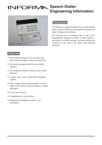
ProgrammingNOTES:SD1 SD1 IntroductionThis manual describes how to install and program all SD1 unitsmanufactured after June 2008. Note that the programming menu for unitsmade after that date is slightly different from the menu in older versions ofthe SD1 , and the recording time has been lengthened to 25 seconds permessage.OverviewThe SD1 sends pre-recorded voice messages over a conventionaltelephone line whenever external equipment triggers one of its four inputs.Any equipment that has a voltage-free contact as an output can provide aninput to the unit. Each input, labelled A, B, C or D, triggers thecorresponding stored message A, B, C or D. In the example shown belowthese inputs are: A- fire, B- Personal Attack (PA), C- Burglary and DAuxiliary.Tel No 1ABCDAuxiliaryInputTelephoneTel No 2SD1 Alarm system controlunit (or otherequipment)A12B45C789DENT0ESC36Tel No 3BT LineSpeech DiallerTel No 4The SD1 also requires a 12VDC supply. Alarm control units, for example,often provide such a supply for connected equipment.When connected to a telephone line the SD1 behaves like anotherextension and does not normally affect the operation of any telephone orother equipment also connected to the line. While the SD1 is sending avoice message other users on the line will hear it should they lift theirhandset.321
IntroductionSD1 SD1 ProgrammingRECORDING MESSAGESProblemPossible CauseActionThe SD1 has a built in microphone to let you record messages directlyinto the unit.The recipient can’tacknowledge the callwith a mobile phone.Weak reception orincompatible telephone.Mobile phones will only workcorrectly if they are used in anarea where the reception is good.Each message comprises two phrases: a common phrase (labelled ‘0’)and one of phrases A, B, C or D. The common phrase normally tells therecipient where the message comes from, and the second phrase tells therecipient what input has been activated.Each phrase can be up to 25 seconds long.PLAYING BACK MESSAGESThe unit’s built-in speaker lets you hear any of the recorded messages.When you play a message, the SD1 always plays phrase 0 first.TELEPHONE NUMBERSThe SD1 can store up to four different telephone numbers, each one upto 24 digits long. You can program and check the numbers from the unit’skeypad and display.The “CLEARBY” option is Check that the option is at theThe recipient hasacknowledged the call set to: “ANY-2” or “ANY- required setting.3” or “ALL-4”but the SD1 continues to dial thesecond, third or fourthnumber.I am pressing the [key for 6 seconds, butI cannot get the“READY” prompt andthe display still shows“PLEASE RECORD” or“SD1 ”.You must key in a fourdigit passcode to gainaccess to theprogramming menu.Enter your user passcode (page11).The SD1 uses pulse or tone dialling, and you can insert pauses for slowresponding exchanges.You can also program the SD1 to send numerical messages to pagers.The unit adds a single digit at the end of the pager message to indicatewhich input has been triggered.DELETING MESSAGES AND TELEPHONE NUMBERSThe SD1 stores the recorded messages and telephone numbersinternally, and you cannot delete them simply by removing the powersupply. A programming option allows you to delete all messages ortelephone numbers at once if you wish to do so, or you can delete themindividually.CALL ROUTINGYou can program the SD1 so that each trigger input will send itsassociated message to any of the stored telephone numbers. Forexample, if you wish the unit to call four different numbers under threedifferent conditions you could program trigger A to call telephone number1, trigger B to call telephone numbers 2 and 3, and trigger C to calltelephone numbers 1, 2, 3 and 4.231
ProgrammingSD1 ProblemPossible CauseActionThe SD1 will nottrigger from the alarmpanel.Incorrect polarity setting.Check that the jumper link is setto the correct position (see page7).Incorrect trigger voltage.Measure trigger voltage andcheck connections (see page 7).The SD1 does notdisplay anything exceptfor “SD1 ” whilst it istriggered.To see the status of the SD1 when triggered use the “Test Call”option (page 28).The unit will not dial the Number enteredprogrammed telephone incorrectly.number.The unit is dialling outthrough an internaltelephone exchange(PABX) that needs apause after initial “9”.Check that you have keyed-in thenumber correctly.Make sure that you haveprogrammed a pause into thenumber after the initial “9” (page14).The unit is wired to anThe unit cannot be with this typeexchange that needs aof exchange. Connect it to aspecial button pressed to standard BT line.select a line.Incorrect telephone lineconnections.The recipient of the call Incorrectcannot acknowledge acknowledgementthe unit by pressing the procedure.“8” button.The recipient is using anincompatible telephone.30IntroductionTHREE WAY CALLINGTrouble Shooting GuideAn input has triggeredthe unit but the displayshows “SD1 ” all thetime.SD1 Check the connections to thetelephone line (see page ).Instruct the recipient in the correctprocedure (see pages 3 and 27).This is a service normally provided by British Telecom. If the service isenabled then the SD1 will use it to prevent anyone trying to block thetelephone line.CALL ATTEMPTSWhen triggered the SD1 rings a programmed number and waits 55seconds (about 20 rings) for an answer. If the called phone does notanswer then the SD1 hangs up and tries again immediately. If the callednumber does not answer for a second time the SD1 hangs up and waitsfive seconds, then calls again for the last time. If the destination still doesnot answer the SD1 hangs up and operates the Fail output (ifprogrammed) for seven seconds.ACKNOWLEDGEMENT OPTIONSOnce the SD1 has made a call and delivered a message, it needs areturn signal to show that the message has been successfully received. If aperson is taking the call they can acknowledge the message by pressingthe number “8” on the their telephone keypad. When the SD1 receives adigit “8” it will stop attempting to send that message until it is triggeredagain. You can program how many times each message must beacknowledged.LAST CALL LOGThe SD1 keeps a log of the last call it has made. The log also showswhich input was triggered last.CALL ABORTIf required, you can program the SD1 so that one of the following eventswill abort a call:Applying a signal to the Abort input (shared with input D).Call the recipient and ask them topress the “8” button on theirtelephone. If you hear anythingother than a tone, the telephone isnot capable of acknowledging theSD1 . This may be overcome byusing a tone pad to simulate thedialling tones. Contact yourinstallation company for details.Removing the input that triggered the unit.Keying in the user passcode.When aborted the unit will stop dialling out immediately, play a chime tone,and show “ABORTED” on the display for a few seconds.PROGRAMMABLE OUTPUTThe SD1 has a single programmable output. When active the outputapplies 0V to its terminal and is capable of sinking up to 100mA of current.3
IntroductionSD1 You can program the SD1 to activate the output for one of the followingconditions:The unit has been triggered and is making calls. The output is activefrom the trigger event until the last required acknowledgement, oruntil the whole series of calls has failed.A call has been successfully acknowledged. The output is active forseven seconds when the unit receives the last required acknowledgesignal.SD1 Display MessagesPLEASERECORDSD1 ABORTEDThe SD1 failed to communicate. The output is active for sevenseconds when the SD1 finally stops calling.SENDING A TEST CALLOnce programmed you can test each message by sending it to a selectedtelephone number. When the unit is in test mode the speaker relayseverything that the unit sends over the telephone line, and the display givesa visual indication of what is happening.PASSCODETo enter programming mode or to cancel calls you must key in a passcodeat the keypad. The passcode is normally four digits long, but if necessaryyou can program the SD1 to accept six-digit passcodes for greatersecurity.Power input:11.5V - 14VCurrent consumption: 35mA (standby); 70mA (Active)Trigger inputs:A, B, C, D ( ve or -ve applied, input voltage 5 28V)Phrases A,B,C,D,0:25 seconds 2 seconds each, sampled at 8KHzTelephone Numbers:4 x 24 digit telephone numbersCase dimensions:150(L) x 104(H) x 30(D) mmREN value:04The unit has no stored messages or telephonenumbers.Either: The unit is in normal standby OR: the unit isdialling out after an input has triggered it.A user keyed in a passcode to abort a call while theSD1 was attempting to dial out. The unit displays thismessage for aborted activations, but NOT for abortedtest calls.The unit displays the following messages during a test call, but NOTduring a normal activation:RINGINGThe unit has detected a ringing signal on the telephoneline.ENGAGEDThe target phone is engaged. Wait until they havefinished and try again.UNOBTAINThe unit has detected the Unobtainable or SpecialInformation Tone. Check that the number is correctand try again.SENT OKSpecificationsProgrammingNO REPLYPAGEDThe unit dialled out, sent the message and wasacknowledged correctly by the recipient.The call was not answered or acknowledged by therecipient.If you have programmed the unit to send a pagernumber, the SD1 will show this message when it hassent the pager message.29
ProgrammingSD1 Options ABCD: Testing MessagesInstallationInstallation RequirementsTo test a message and it’s telephone numbers:1. Make sure the SD1 is not currently sending anymessages.SD1 2. Key in the current passcode.READY3. Press either A, B, C or D depending on whichmessage you want to test. The display shows, forexample “SEND A” alternating with “ON 1-4”:SENDa AON 1-4EITHER:A) Press A.PHRASE AThe unit plays message 0 followed by message A.The display shows, for example “PHRASE A”:ZCooper Security supplies the SD1 with a 2 metre telephone lead whichwill plug directly into any standard BT socket. Cooper Security recommendthat you site the SD1 as near to a BT telephone socket as possible. If thisit not possible you can either use an approved BT extension lead or wirethe unit to the BT. socket (see page 8).Mounting Instructions2. Hold the base in position (keyhole to the top) and mark the threesecuring holes. Remove the base then drill and plug the holes.READY3. Pass all cables into the base through the cable entries and then securethe base to wall.PCB LayoutOR:B) Press a digit 1 to 4. The SD1 sends message 0and the message A (or B or C or D depending on thekey you pressed in step 3) to the telephone numberyou selected (1 to 4).ZThe SD1 is designed for connection to an intruder alarm control panel orsimilar equipment. The control panel must have an auxiliary power outputof between 11.5V and 14V, with the ability to provide a minimum of100mA.1. Separate the cover from the base by using a screwdriver to push twoof the retaining clips (top or bottom) inwards from the base indents.Remove cover assembly and store in a safe place.If you wait five seconds without pressing a key thenSD1 plays message 0 followed by the messageassociated with the key you pressed in step 3.Once the SD1 has finished playing the messagesthe screen shows “READY”:SD1 Note: Ask the person answering the call toacknowledge the message by pressing ‘8’ on theirphone keypad. Otherwise the SD1 will workthrough a complete cycle of four calls for thatmessage.1. Loudspeaker2. Tamper Switch3. Microphone4. Tamper connections (SELV)5. Trigger Inputs (SELV)6. Trigger Polarity jumper7. Telephone Connections (TNV)8. 12V Supply and ProgrammableO/P (SELV)9. Factory Restart PinsSELV Safety Extra Low Voltage, TNV Telecommunications Network Voltage.285
InstallationSD1 SD1 ProgrammingSD1 ConnectionsOption 0: Acknowledgement OptionsCaution: Before making any connections to the SD1 remove thepower (battery and 240V mains) from the equipment you intend toconnect the unit to.Once the SD1 has made a call and delivered amessage, it needs a signal to say that the message hasbeen successfully received. This is done by the recipientpressing the number “8” on their telephone. When theSD1 receives the “8” it stops attempting to send thatmessage until triggered again.ZConnections on the SD1 are either “Safety Extra-Low Voltage”circuits (SELV) or “Telecommunication Network Voltages” circuits(TNV). Connect TNV circuits only to the PSTN. Connect SELV circuitsonly to other circuits designated as SELV circuits.ZRoute cabling to the telephone line connections (TNV) well away fromthe trigger input circuitry (SELV). Route cabling to the trigger inputcircuitry (SELV) well away from the telephone circuitry (TNV).The SD1 provides the following connections:Trig Inputs (see figure on page for connection diagram):A:When triggered, the unit starts the dialling sequence and sendsmessage A.B:When triggered, the unit starts the dialling sequence and sendsmessage B.C:When triggered, the unit starts the dialling sequence and sendsmessage C.Option 0 determines how many calls must beacknowledged before the SD1 stops attempting tosend a message.1. If necessary initialise the SD1 .2. Key in the current passcode.3. Press 0, the display shows:4. Press [, the display shows the currentacknowledgement option, for example:The options available are:You can select Trigger/Abort inputs to be either ve applied to triggeror -ve applied to trigger. Set the “Trigger Polarity” jumper-link to theappropriate position (see figure on page ).TAMP:These two voltage free terminals are connected directly to thenormally closed tamper switch. You can connect them to themain tamper zone on the alarm control panel, to provide casetamper protection for the SD1 .0V:Connect to a permanent 0V supply on the control panel. 12V:Connect to a permanent 12V supply on the control panel.O/P1:A switched -ve @100mA programmable output (see page 23).6READYCLRBYANY-1“ANY-1” at least one call must be acknowledged.“ANY-2” at least two calls must be acknowledged.ABORT/D: If the SD1 is programmed as “ABORT by INPUT” thisconnection can be used to abort the dialling sequence. If theSD1 is not programmed as “ABORT by INPUT” thisconnection can used as trigger input D.ZSD1 “ANY-3” at least three calls must be acknowledged.“ANY-4” all four calls must be acknowledged.“NO-ONE” no acknowledgement required.5. Press B repeatedly until the display shows the optionyou want to use, for example:5. Press [ to save the change and return to “READY”.ZANY-2READYNote: If you select NO-ONE and also program the output as FAILED(see page 23 ) then the output will not operate.27
ProgrammingSD1 Option 9: Last Call Log2. Key in the current passcode.3. Press 9, the display shows: -SD1 SD1 READYVIEWLOG-N.O.LoopN.C.LoopTRIG ATRIG BTRIG C1Kresistor 12V0VN.C.LoopN.O.LoopSD1 TRIG ATRIG BTRIG C 12V on alarmTRIG A Normally Closed InputTRIG B Normally Open InputTRIG C Switched ve Input-1Kresistor0V on alarmTRIG A Normally Open InputTRIG B Normally Closed InputTRIG C Switched -ve InputCONTROL PANEL CONNECTIONSA)--3-If the display shows:“A)----“ then none of the calls for message A wereacknowledged.“BLANK” then the log is empty.5. Press [ to return to “READY”.TRIG POLARITY 12V0V4. Press [.The display shows the last event recorded by theunit. In the example shown at the right, the unit sentmessage A to telephone number 3, whichacknowledged the call.InstallationTRIG POLARITYOnce someone has acknowledged a call, the SD1 stores a record of the event. You can see that recordusing option 9.1. If necessary initialise the SD1 .SD1 READYThe table below lists the connection details to various control panels.Control PanelTRIG AMenvier TS400/TS410Menvier TS510Menvie
Cooper Security Ltd Security House Vantage Point Business Village Mitcheldean Gloucestershire GL17 0SZ www.coopersecurity.co.uk Product Support (UK) Tel: 44 (0) 1594 541979. Available between: 08:15 and 17:00 Monday to Friday. Product Support Fax: (01594) 545401 Part No: 11832027 SD1 S