Transcription
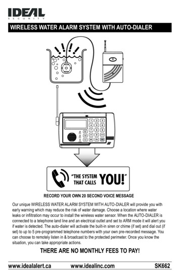
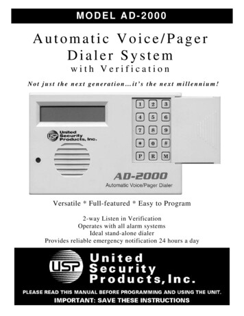
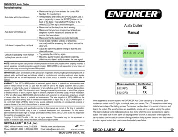
ENFORCER Auto DialerTroubleshooting:Auto dialer will not arm/disarmAuto dialer will not dial outUnit doesn’t respond to a call-backDifficulty in activating ‘room monitor’by telephone remote control Make sure that you have entered the correct PINNumber. Try re-entering it. While pressing and holding the [PROG] button, use apen or paper clip to press the [RESET] button on theback of the dialer. This sets the PIN number to thedefault (000).Then try to arm/disarm again. Make sure that the telephone line is working. Make sure that you have programmed at least onetelephone number into the unit and that the fullnumber has been stored. Make sure that the system is in Auto Dial mode. Check to see if another unit (fax or answeringmachine) could be answering the call and remove theother unit. Adjust the call-in ring detect setting so that the autodialer will answer. Try pressing the code key again. Move to a quieter location as ambient noise mayaffect the auto dialer’s ability to detect the tone signal.Auto DialerManualNOTE: While the system can provide valuable protection to home and property when properly installed, itcannot guarantee complete protection against intrusion. SECO-LARM is not responsible for any losses ordamage which may occur during the use of this product.IMPORTANT: Users and installers of this product are responsible for ensuring this product complies with allnational, state, and local laws and statutes related to monitoring and recording audio and video signals.SECO-LARM will not be held responsible for the use of this product in violation of any current laws orstatutes.WARRANTY: This SECO-LARM product is warranted against defects in material and workmanship whileused in normal service for one (1) year from the date of sale to the original customer. SECO-LARM’sobligation is limited to the repair or replacement of any defective part if the unit is returned, transportationprepaid, to SECO-LARM. This Warranty is void if damage is caused by or attributed to acts of God, physicalor electrical misuse or abuse, neglect, repair or alteration, improper or abnormal usage, or faulty installation,or if for any other reason SECO-LARM determines that such equipment is not operating properly as a resultof causes other than defects in material and workmanship. The sole obligation of SECO-LARM and thepurchaser’s exclusive remedy shall be limited to the replacement or repair only, at SECO-LARM’s option. Inno event shall SECO-LARM be liable for any special, collateral, incidental, or consequential personal orproperty damage of any kind to the purchaser or anyone else.NOTICE: The information and specifications printed in this manual are current at the time of publication.However, the SECO-LARM policy is one of continual development and improvement. For this reason,SECO-LARM reserves the right to change specifications without notice. SECO-LARM is also not responsiblefor misprints or typographical errors.Copyright 2014 SECO-LARM U.S.A., Inc. All rights reserved. This material may not be reproduced orcopied, in whole or in part, without the written permission of SECO-LARM.SECO-LARM U.S.A., Inc.16842 Millikan Avenue, Irvine, CA 92606Phone: (949) 261-2999 (800) 662-080016Website: www.seco-larm.comEmail: sales@seco-larm.com PIHLK1MiE-921APQ 141029.docxSECO-LARM U.S.A., Inc.Models AvailableCertificationE-921APQE-921GPQWhen triggered by an alarm system, the ENFORCER Auto Dialer can call up to 5 numbers. Eachnumber can contain up to 32 digits, including #, tones, and pauses. The LCD shows the number beingdialed at each stage of the dialing process. The receiver can then listen in to sounds in the room anddisarm the system. The same functions are available by remote call in as well as arming the system.The dialer includes a home mode (acting like a door chime when the owner is present) and a panicbutton. The 105dB built-in siren alarm can be programmed on or off. It also allows for the option of abackup battery (not included) to continue offering protection during a power loss and uses flash memoryto protect against system data loss in case of extended power failure.
ENFORCER Auto DialerENFORCER Auto DialerSummary Programming/Operation Chart:Table of Contents:Features . 2Parts List . 3Specifications . 3Wiring Diagram . 3Overview . 4LCD Screen Layout . 4Installing the Auto Dialer . 5Programming the Auto Dialer . 6 9Setting and Changing the PIN Number . 6Setting Emergency Phone Numbers . 6 7Deleting a Stored Phone Number . 7Setting the Siren Function . 7Setting the Auto Dial Function . 8Setting the Number of Auto Dial Cycles . 8Setting the Number of Call-in Rings . 8Setting the Entry Delay Time . 9Setting the Date and Time . 9Testing the Auto Dial Function . 9Resetting the Auto Dialer . 9Operating the Auto Dialer . 10 13Arming and Disarming the System . 10Panic Button Use . 10Remote Control by Telephone . 11 12Home Mode Use . 12Low-Battery Indicator . 13View Function . 13Tips . 13Also Available from SECO-LARM . 13Program Planner . 14Summary Programming/Operation Chart . 15Troubleshooting . 161. Setting/Changing PIN Number (see pg. 6)Current PIN [PROG] [ARM/DISARM] New PIN [ARM/DISARM] [PROG] x92. Setting Emergency Phone Numbers (see pgs. 6 7)PIN[PROG]x2[ARM/DISARM][#/DOWN] or[*/UP]Enter DISARM][PROG]x83. Deleting a Stored Phone Number (see pg. 7)PIN[PROG]x2[ARM/DISARM][#/DOWN] or[*/UP]4. Setting the Siren Function (see pg. 7)PIN [PROG] x4 [ARM/DISARM] [#/DOWN] or [*/UP] [ARM/DISARM] [PROG] x65. Setting the Auto Dial Function (see pg. 8)PIN [PROG] x5 [ARM/DISARM] [#/DOWN] or [*/UP] [ARM/DISARM] [PROG] x56. Setting the Number of Auto Dial Cycles (see pg. 8)PIN [PROG] x6 [ARM/DISARM] [#/DOWN] or [*/UP] [ARM/DISARM] [PROG] x4Features: 7. Setting the Number of Call-in Rings (see pg. 8)16-Digit large display with date/time and function icons2 (N.C.) Triggers for multiple zone securityRemote monitoring – user can call in to listen in to room sounds and arm/disarm dialerRemotely listen in to room sounds or disarm during call backProgrammable PIN number and entry delay timing5 Programmable emergency telephone numbers (up to 32 digits each)Programmable auto-dialing cycle repeat timesHome mode function (acts as a door chime when user is at home)Panic buttonBuilt-in flash memory to protect against system data loss in case of power failureTouch-Tone dialingPhone jackLow-battery indicator for backup battery (battery not included)DC power input jack (3.5mm phone jack, not included)9V battery backup (battery not included)Wall-mountableBuilt-in 105dB alarm (with programmable alarm on/off)Built-in auxiliary output for external alarm or sirenPIN [PROG] x7 [ARM/DISARM] [#/DOWN] or [*/UP] [ARM/DISARM] [PROG] x38. Setting the Entry Delay Time (see pg. 9)PIN [PROG] x8 [ARM/DISARM] [#/DOWN] or [*/UP] [ARM/DISARM] [PROG] x29. Setting the Date/Time (see pg. 9)PIN[PROG]x9[ARM/DISARM][#/DOWN] or[*/UP][ARM/DISARM]Repeat for each [PROG]positionx210. Test Auto Dial Function (see pg. 9)(In Standby Mode) Press and Hold [PROG] [#/DOWN] or [*/UP]Check to see if number is dialed11. Arm/Disarm System (see pg. 10)PIN[ARM/DISARM]12. Remote Control by Telephone (see pgs. 11 12)Receive CallDial Voice Dialer NumberPress Key Code on Telephone KeypadPress Key Code on Telephone Keypad13. Activate/Deactivate Home Mode (see pg. 12)(In Standby Mode)[HOME]14. View (see pg. 13)Last 5 Sensor Trigger Records(In Standby Mode) [#/DOWN]Stored Emergency Telephone Numbers (In Standby Mode)[*UP]2SECO-LARM U.S.A., Inc.SECO-LARM U.S.A., Inc.15
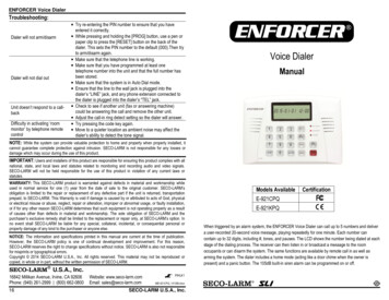
ENFORCER Auto DialerENFORCER Auto DialerParts List:Program Planner:Use these charts during setup to record phone numbers and sensor locations for future reference.It is recommended that you use a pencil during setup and redo it in ink afterwards. The usershould keep in a safe, easily accessible location and a copy should be retained by the installer.Program: NumbersNUMBERPRIORITYDate:TELEPHONE NUMBER(include area code and dialer prefix as needed, addPBX pause and extension if applicable, see p. 6-7)NAME OF PARTY TO BE REACHED1x1x2x1xAuto dialer unitRemote control instruction cardPlastic wall anchorsWall mounting template1x1x2x1xTelephone cableDual outlet telephone jack adapterWall mount screwsUser manualSpecifications:Operating voltage9 12 VDC5mA10mA180mA5329VDC/ 20h 105dB2 x N.C. Trigger 500ms125mA32 104 F (0 40 C)-4 140 F (-20 60 C)6.2-oz (175g)33/8"x45/16"x17/8" (86x110x47 mm)StandbyCurrent drawDialingMax. (at 12VDC)Alarm OnProgrammable emergency phone numbersMaximum digits per telephone numberBackup battery type/life (not included)Alarm sound level at 12" (30cm)Trigger inputsTrigger input timerAuxiliary output current (max)Operating temperatureStorage temperatureWeightDimensions12345For Future UseWiring Diagram:Telephone Wall JackInstallation: TriggersTRIGGERGENERAL DESCRIPTIONBack Connection Area (Cover Removed)Date:SENSOR LOCATIONS-External Alarm/Siren E-964-D390Q*-1Trigger 1 Trigger 2ResetGRDCOM.SirenDC Output 9 12VDC125mA Max.ENFORCER External PowerSupplyorPower Adapter(3.5mm Phone Plug,Not Included)2SM-200Q*SM-206Q*14SECO-LARM U.S.A., Inc.SECO-LARM U.S.A., Inc.* E-964-D390Q Photobeam Detectors, SM-200Q MagneticSensors, and SM-206Q Concealed Magnetic Sensors shown asexamples only: For other sensors and products available fromSECO-LARM, please visit our website at www.seco-larm.com.3
ENFORCER Auto DialerOverview:ENFORCER Auto DialerOperating the Auto Dialer, continued:FrontDC Power LEDLow-Battery (LOW BATT.) IndicatorLow Battery LEDWhen the charge level of the 9VDC backup battery (not included) is low, the “LOW BATT.” LEDwill flash once every 1.5 seconds. Replace the battery in order to continue providing functionalityduring a temporary disruption in power.LCD DisplayNumeric KeypadNote: In order to avoid potential damage due to battery leakage, do not leave a low battery inthe unit. Also, be sure to remove the battery if the unit is unused for a period of time.Back (Covers Removed)Mounting PointsView FunctionTerminal BlockTo view the last 5 sensor trigger events, while in standby mode press the [#/DOWN] button.Reset ButtonTo view stored emergency telephone numbers, while in standby mode press the [*/UP] button.Battery Receptacle (Battery not included)Left SideRight SideSiren SpeakerTips:LINE Jack1. Make sure that the full telephone numbers have been stored as they would normally be dialedfrom a local phone.DC Power Jack (for 3.5mm phone plugadapter, not included)2. The auto dialer is only suitable for single phone lines. It is not compatible with fax machines.Home Mode Button3. Set the number of Call-in rings to be less than the voicemail or message answer point.Also Available from SECO-LARM :LCD Screen Layout:Home ModeActivatedDoor/Window Switches,Magnetic Contacts, etc.Voice DialerSL-1301-BAQShock/Vibration DetectorTamper SwitchPhotobeam SensorSS-040QSS-072QE-931-S35RRQLED Strobe LightAuto DialSiren AlarmAlarm TriggeredPASSWORD MEMORY LEARN Time/DateCall-Back RingsArmed HOMEE-921CPQ ARMNote: For explanation of these symbols, please see Programming the Auto Dialer on pages 6 9.4Note: After 10 seconds of inactivity, the dialer will automatically exit the view mode and returnto standby.SECO-LARM U.S.A., Inc.For a complete listing of SECO-LARM products, please visit us online at www.seco-larm.com.SECO-LARM U.S.A., Inc.13
ENFORCER Auto DialerENFORCER Auto DialerOperating the Auto Dialer, continued:Installing the Auto Dialer:Remote Control by Telephone – Function Explanations, continued:Note: You can program the telephone numbers and voice messages prior to connecting thepower as long as the 9V battery is installed. The standby battery should provide about 20 hours ofoperation.END CALL - Pressing [3 #] will end the call.ARM SYSTEM – Pressing [5 #] during a user callback will arm the system, confirming withthree short “beeps,” and automatically hang up. If there are 5 rapid “beeps” after three short“beeps,” it means a door/window is not closed. The dialer will then give 5 seconds to disarmthe system.DISARM SYSTEM – Pressing [6 #] will disarm the system and automatically hang up.Note: If the user enters an incorrect password or key code, the dialer will sound 5 “beeps”and automatically hang up.Home Mode UseTo turn off the alarm function and use the dialer as a door chime, set the dialer to “Home” mode. Achime will ring any time one of the sensors is triggered.Note: The Auto Dialer uses EEPROM to retain memory in the event of a power loss.1. Select a location for the dialer near a standard electricaloutlet (if user-supplied 12VDC adapter is to be used), atelephone wall jack, and the alarm control panel, but out of5 6ftsight. The dialer should not be exposed to direct sunlight or (1.5 2mrain, and must not be mounted near heat sources such as)radiators, heating ducts, or stoves.2. For wall-mount, use the wall mounting template to drillholes and attach 2 screws into the wall at the desiredlocation. For convenience, 5 6ft (1.5 2m) above the flooris recommended (Fig. 1).To activate the “Home” mode:3. Remove the cable cover and battery cover from the back ofthe auto dialer (Fig. 2).1. Press the [HOME] button on the left side of the dialer. One chime will sound and the word‘HOME’ will appear on the LCD screen.4. Install a 9VDC backup battery (not included). Reattach thebattery cover.2. After 60 seconds, another chime indicates that the dialer is now in the “Home” mode.5. Connect the dialer to two detectors or groups of detectors inseries using the connection terminals as shown in the wiringdiagram (see pg. 3). The dialer can also be connected to twoseparate alarm control panel outputs of a separate alarmsystem. If an external siren/alarm is desired, connect as shownon the wiring diagram.3. When a sensor is activated, the dialer will chime twice.4. If the panic button is pressed, the dialer will sound a 30-second alarm and start the dialingsequence to the programmed emergency numbers.To deactivate the “Home” mode, simply press the [HOME] button again.Note: Arming the system deactivates the “Home” mode. After disarming, reactivate the“Home” mode if desired.Fig. 1CableCover9VDC Battery(not included)BatteryCoverFig. 26. Power:a. If the dialer is to be powered from the alarm control panel,connect the alarm power outputs to the terminal block (see pg. 3).Fig. 3b. If using a 12VDC adapter (not included), plug the adapter into the dialer’s DC power jack.7. Connect one end of the included telephone cable to an existing Touch-Tone line wall socket,and the other end to the dialer’s “LINE” jack. Optionally, use the included dual outlet telephonejack adapter to connect an extension telephone using the telephone’s cable (not included)(Fig. 3).8. For wall installation, place the unit over the heads of the screws installed in step 2 (Fig. 1) andslide down. Check that the unit is firmly attached and tighten or loosen the screws as needed.9. Once all connections are made, the dialer is ready to be programmed.12SECO-LARM U.S.A., Inc.SECO-LARM U.S.A., Inc.5
ENFORCER Auto DialerENFORCER Auto DialerProgramming the Auto Dialer:Operating the Auto Dialer, continued:The setup mode may only be accessed when the dialer is in standby mode. If no key is pressedwithin 15 seconds, the dialer will automatically exit the setup mode.Remote Control by TelephoneSetting and Changing the PIN Number1. Enter the current PIN number (factory preset PIN number is ‘000’), and press the [PROG]button once. ‘PASSWORD’ will flash on the LCD.2. Press the [ARM/DISARM] button to accept.3. Enter a new PIN number (3-6 digits) followed by the [ARM/DISARM] button to confirm.4. Press the [#/DOWN] or [*/UP] button to select other setup categories or press the [PROG]button until the programming icons disappear to exit the setup mode.Note: If the PIN number is forgotten, press and hold the [PROG] button and use a pen orpaper clip to press the [RESET] button located under the cable cover on the back of the unitand release. The unit will return to the factory preset PIN number (000). All other userprogrammed settings except the date and time will be retained.Setting Emergency Phone Numbers1. Enter the PIN number and press the [PROG] button twice or until “MEMORY” flashes on theLCD screen.The system can be remotely controlled and monitored through any Touch-Tone phone, includingmobile phones. The user may arm or disarm the system as well as listen in on the room.1. REMOTE CONTROL WHEN ALARM IS ACTIVATEDWhen an alarm has been activated and the auto dialer dials the pre-programmed emergencynumbers, the person who answers the call will hear a single “beep" for a sensor trigger or 4“beeps” for panic button activation and may press one of the following function codes at anytime to control the system remotely:FunctionPress key codeListen in1#End call3#Disarm system6#The user should hear a “beep” in response. If not, enter the function code again.2. REMOTE CONTROL BY USER CALL-IN (CALL BACK)A. Using a mobile phone or any Touch-Tone phone, dial the phone number that the autodialer is connected to. The auto dialer will answer and “beep” once after the number ofrings in the pre-programmed call-in ringer detect cycle (3, 5, 7, or 10 rings, see pg. 8).2. Press the [ARM/DISARM] button to accept.B. Enter the PIN Number on the phone’s keypad. The dialer will “beep” twice if the correctcode has been entered. If a wrong code is entered, the dialer will disconnect automaticallyand the user must dial in again.3. Press the [#/DOWN] or [*/UP] button to select one of the number locations 1-5.C. Press one of the following function codes to control the system remotely:Note: The 5 number locations represent the order in which the numbers will be dialed in thecase of an alarm.4. Enter the number to store including any area codes or dialing prefixes if needed (up to 32digits, although only the last 16 digits can be shown on the LCD display) using the keypadfollowed by the [ARM/DISARM] button to accept and store the number.Note: If needed, add a 4-second ‘pause’ before a PBX extension number by pressing andholding the [DEL/PAUSE] button for 2 seconds until the letter ‘F’ appears on the LCD screen,and then continuing with the extension number as usual. A ‘#’ or ‘*’ can also be entered bypressing, and holding for two seconds, the [#/DOWN] or [*/UP] buttons respectively. The ‘#’sign shows as ‘ ’ and the ‘*’ sign shows as ‘ ’ on the LCD screen.Example 1 – To store a number with area code 1-214-555-2858 and an office extension 205(where the PBX requires a 2-second pause before the extension): After scrolling to the desirednumber location, enter ‘12145552858,’ press the [DEL/PAUSE] button for 2 seconds until theletter ‘F’ appears on the LCD screen, enter ‘205’ and press the [ARM/DISARM] button.6SECO-LARM U.S.A., Inc.FunctionListen inArm systemDisarm systemPress key code1#5#6#The user should hear a “beep” in response. If not, enter the function code again.Note: Should the user have difficulty activating functions remotely by telep
ENFORCER Auto Dialer 2 SECO-LARM U.S.A., Inc. Features: 16-Digit large display with date/time and func