Transcription
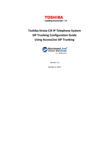
WIRELESS ALARM SYSTEM WITH TELEPHONE AUTO DIALERBAT.LOW“THE SYSTEMTHAT CALLSYOU!AC”Our WIRELESS ALARM SYSTEM WITH TELEPHONE AUTO DIALER is designed to allow you tocreate your own security system. When the AUTO DIALER is connected to a telephone land lineand an electrical outlet and set to ARM mode it will alert you when any of the sensors have beentriggered. The auto-dialer will activate the built-in siren or chime (if set) and dial out (if set) to up to5 pre-programmed telephone numbers with your own pre-recorded message. You can choose toremotely listen in & broadcast to the protected perimeter. Once you know the situation, you can takeappropriate actions.There are no monthly fees to pay!www.idealalert.ca SK634
Thank you for choosing Ideal Security’s Home Security System with Telephone Auto Dialer. If you have any questions,problems or comments regarding the installation or operation of this system, please do not hesitate to contact IDEAL’scustomer service department through our web site at www.idealalert.ca, via email at info@idealalert.ca, or by calling ourtoll free number at 800-361-2236 x 230. Normal business hours 7:30 AM to 3:00 PM Eastern time. Monday to Friday.Occasionally instructions have errors or omissions, please check for updates to these instructions, security tips andother valuable information at www.idealalert.caTHIS PACKAGE INCLUDES: 1 MOTION SENSOR 1 AUTO-DIALER 1 INDOOR/ OUTDOOR SIREN WITH LED STROBE 2 REMOTE CONTROLS ALL BATTERIES AND AC/DC ADAPTERS. 2 WINDOW / DOOR CONTACTSNOTE: BEFORE PERMANENTLY INSTALLING ANY OF THE DEVICES INCLUDED IN THIS PACKAGE PLEASE TESTTHE RANGE OF ALL UNITS TO MAKE SURE THAT THE RECEIVER PICKS UP ALL THE SENSORS.NOTE: THE TELEPHONE DIALER REQUIRES AN ELECTRICAL OUTLET AND A TELEPHONE LAND LINEWITH TONE DIALING TO MAKE OUTGOING CALLS.SETUP OVERVIEW Set your passcode (refer to AUTO-DIALER SET-UP section 1)Program telephone numbers (refer to AUTO-DIALER SET-UP section 4)Record your notification message (refer to AUTO-DIALER SET-UP section 2)Install door/window sensors (refer to INSTALLATION OF SENSORS section)Install motion sensor (refer to INSTALLATION OF SENSORS section)Install indoor/outdoor siren (refer to WIRELESS INDOOR/OUTDOOR SIREN & STROBE LIGHT section)It’s done!You can now activate the system and be protected with this simple, effective wireless security system with auto dialer.NOTE: To change the default settings and expand the system, follow the detailed instructions provided in this manual.IMPORTANT SAFETY TIPS1. Do not install the system where it will be exposed to direct sunlight or rain.2. The built-in siren is very loud, never put the system close to your ear.3. The system should be installed away from heat sources such as radiators, heating ducts and stoves.4. If the system sounds at random, it is possible that the installed location is too close to a heat source, changing the locationor direction of the unit may correct the problem.5. The system can provide valuable protection for your home and property if utilized properly. However, this unit cannotguarantee complete protection against burglary or property damage. Therefore, we will not be responsible for any lossesor damages which may occur, while using this product.ANSWERING MACHINES AND REMOTE COMMUNICATIONIf you intend to use the REMOTE ACTIVATION features (controlling the alarm unit remotely) of the Auto Dialer, you cannotuse an answering machine.To use the remote activation feature: Set the auto dialer to respond (pick up) before your answering machine responds. Forexample, if your answering machine is set to pick up after 5 rings then set the auto dialer to pick up after 3 rings, this wayyour AUTO DIALER will pick up first, allowing you to enter your key selection. Complete instructions on setting up the remoteactivation follow.If the answering machine is required, then the REMOTE ACTIVATION feature cannot be used.Set the auto dialer to respond after your answering machine normally responds (set it to 10 rings) this will ensure that theanswering machine is first to respond.
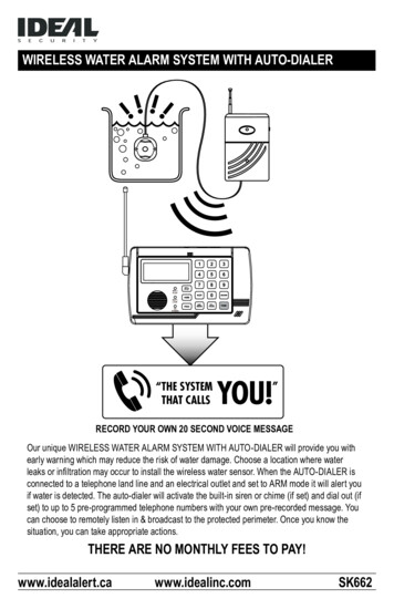
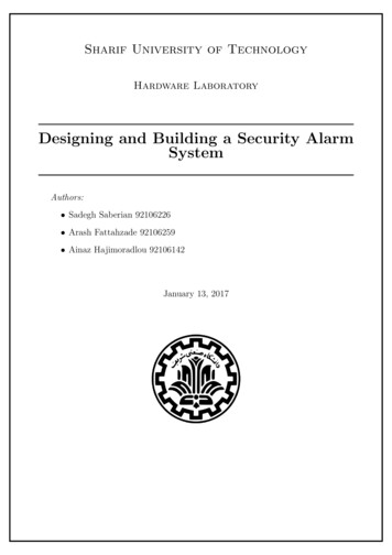
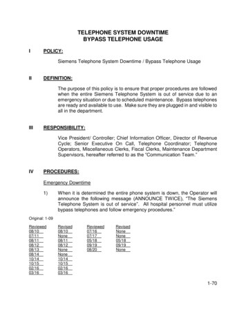
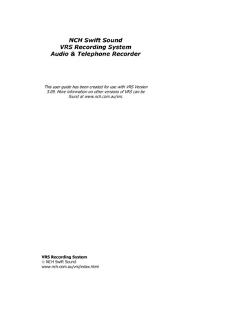
TELEPHONE AUTO DIALERLINETEL.OPEN10 11 12131614 15DESCRIPTION OF COMPONENTS1. Antenna Jack5. REC./Play LED2. Antenna6. Battery Low LED3. LCD Display7. Power LED8. Numeric Keypad4. Voice SpeakerFEATURES Receives signals from wireless sensors - activatesTelephone auto-dialer and alarm Room monitor by telephone function Programmable voice message for telephone alert ARM or DISARM system by telephone Programmable password Entry delay timing (set time for how long after trigger eventbefore the auto dialer will dial out and siren will sound) Up to 5 emergency telephone numbers (up to 32 digitseach) (only last 16 digits appear on LCD screen) Programmable auto dialing cycle (number of times theauto dialer will dial each programmed phone number)up to 5 cycles Built-in 105 dB alarm (with programmable alarm on/off) HOME mode function (auto dialer will chime but not dialout when sensors are triggered)9. Microphone10. To Wall Jack (LINE)11. To Telephone (TEL.)12. DC 9V Jack 13. Battery Cover14. Reset Button15. Siren speaker16. Wired Input Terminal*16 Digit, large number display10 zone icons for easy differentiation of sensor locationsZones 1 - 8: Can link one wireless sensor to each zoneZone 9: Can link up to 8 wireless sensorsREMOTE zone: Can link up to 8 remote controlsRecords the five most recent triggered alarmsBuilt-in flash memory to protect system data during apower failure. If the battery dies, all info will remain in autodialer except the date and time.Battery Low indicator. We recommend that the batteryin the dialer be changed at least once per year, as youchange your smoke detector battery.Wired sensor input terminal (to connect Ideal’s wiredwindow and door contacts SK619)AC adaptor and 9V battery back-up (included)Wall mountable (screws and anchors included)INSTALLATIONNOTE: The Dialer Unit must be installed where it has access to a land line and an electrical outlet. Install 9V battery included (Fig 1). The battery installed in this unit is a back-up battery only. This battery will keep the unitworking for a limited time during a power failure. Position the antenna vertically (straight up) for better reception. (Fig. 2) Connect the included phone cord to the jack on the control unit labeled “LINE”. Connect the other end of the cord to yourwall jack. (Fig. 3a)NOTE: If you are using a DSL service, a DSL filter must be instaled between the auto dialer and the wall jack. A phone can be connected to the unit using the “TEL.” jack. (Fig. 3a) Check to see if you have a dial tone. Connect the AC adaptor to the DC 9V jack on the auto-dialer. (Fig. 3b)* For complete instructions on how to add wired components to the auto-dailer visit; www.idealalert.ca
LINE(LINE)To wall socketTEL.LINETEL.(TEL.)To telephoneDC 9V Adaptor( Fig. 3a )( Fig. 3b ) Wall mount option: Choose a suitable location where you have access to a telephone line and electrical outlet,drill holes using template provided and install anchors and screws. Place the auto-dialer over the screws and slideit down to secure it in place.AUTO-DIALER SET-UPNOTE: If no key is pressed for 20 seconds, the auto-dialer will automatically exit set-up mode. Set-up is done in DISARM mode only. The auto-dialer has a factory preset password of 0-0-0. This should be changed to your own personal password.1. TO CHANGE PASSWORD Enter factory pre-set password 0-0-0. Press PROG button once (1), PASSWORD will flash on the auto-dialer screen. Press the ARM/DISARM button to confirm that you want to enter the PASSWORD. Enter your new password then press the ARM/DISARM button to confirm your password has been stored(you can choose from 3 to 6 digits for your password). Press the PROG button nine (9) times to exit set-up mode.NOTE: PASSWORD RESETIf you forget your password, locate the RESET button on the back of the unit. Press and hold the PROG button, and, pressand release the reset button once. The screen will go blank. When screen returns let go of the PROG button. You now havethe factory pre-set password of 0-0-0. This will reset the password ONLY, all other information will remain (programmedtelephone numbers and learned sensors).2. RECORD PERSONALIZED NOTIFICATION MESSAGEYou can record a single personalized 20 second message that will be played back when you receive telephone notificationthat your system has been triggered. To help remember the options you have, your message should be similar to:“[Your name’s] security system has been triggered, please enter a command; to Monitor Room press 1 and #, to Broadcastpress 2 and #, to End Call press 3 and #, to Disarm System and end call press 6 and #”. Enter password then press REC/PLAY once. Clearly and slowly dictate your 20 second message. Press REC/PLAY to end recording. The recording will automatically end after 20 seconds. The message will replay onceafter recording is finished. Press REC/PLAY to replay message at anytime.3. SETTING THE TIME (YEAR / MONTH / DATE / HOUR / MINUTES) Enter password then press the PROG button nine (9) times. Will flash on the auto-dialer screen. Press ARM/DISARM button to confirm. The date will show on the auto-dialer screen as five sets of numbers: year, month, and date followed by the time hour andminutes (24 hr. time clock). The first set of numbers will flash confirming that these can now be changed. Enter correct year by pressing */UP or #/DOWN button, then press the ARM/DISARM button. The next set of numbers willstart flashing, enter the month by pressing */UP or #/DOWN button, then press the ARM/DISARM button. Continue untilyou have the correct date and time. Press PROG button once (1) to exit set-up mode.4. TO PROGRAM EMERGENCY TELEPHONE CALL NUMBERS Enter password followed by PROG button twice (2). MEMORY will flash on the auto-dialer screen.
Press ARM/DISARM button to confirm. You are now ready to program up to 5 emergency telephone numbers. Press the */UP or #/DOWN buttons to selectmemory location from 1 to 5. If you select 2 this is where your number will be stored and it will be the 2nd number dialed. Enter the telephone number you would like to store, as you would normally dial it in your area (maximum of 32 digits, thescreen will only display the last 16 digits), followed by ARM/DISARM to confirm. Repeat steps for the four other numbers you may wish to store. DO NOT use 911 as on of the stored telephone numbers. Press PROG button eight (8) times to exit the set-up mode.5. TO DELETE A TELEPHONE NUMBER FROM MEMORY Enter password followed by PROG button twice (2). “MEMORY” will flash on the auto-dialer screen. Press ARM/DISARM button to confirm. Press */UP or #/DOWN buttons to select the number you want to delete. Press DEL./PAUSE button to delete the number. Press the ARM/DISARM button to confirm. Press PROG button eight (8) times to exit the set-up mode.6. PAUSE FUNCTIONThe “PAUSE” function can be stored as one digit in the telephone number memory for some dialing operations. Every onePAUSE in the memory dialing sequence will pause for 3.6 seconds. For example, if you want to store telephone number514-363-1030 EXTENSION 230 to memory location 2, the operation will be as following: Enter password then press PROG button twice (2). “MEMORY” will flash on the auto-dialer screen. Press ARM/DISARM button to confirm. Press */UP or #/DOWN button to select memory location 2. Enter 5143631030 press and hold DEL./PAUSE for 2 seconds until the letter F appears on the screen, then enter 230. Press ARM/DISARM button to confirm. Press PROG button eight (8) times to exit set-up mode.7. TO PROGRAM AUTO CALL FUNCTION ON/OFFThe auto-dialer has been factory pre-set with the call option ON.If you do not want the auto dialer to call out change this to OFF: Enter password followed by PROG button five (5) times. The “” icon will flash on the auto-dialer screen. Press ARM/DISARM button to confirm. Using */UP or #/DOWN buttons to select call OFF followed by the ARM/DISARM button to confirm. Press PROG button five (5) times to exit the set-up mode.8. TO PROGRAM AUTO DIALING CYCLE (how many times the auto dialer will call the programed numbers).The auto-dialer has been factory pre-set to auto dial for 1 cycle (When a sensor is triggered the auto dialer will call all storednumbers 1 time). You can change the number of cycles from 1 to 5 dialing cycles. Enter password followed by PROG button six (6) times. “CYCLE” will flash on the auto-dialer screen. Press ARM/DISARM button to confirm. Using */UP and #/DOWN buttons to select number of cycles between 1 and 5 followedby the ARM/DISARM button to confirm. Press PROG button four (4) times to exit set up mode.9. TO TEST MEMORY DIALINGIn standby mode, press and hold the PROG button for at least 3 seconds, you will hear a short beep. Key in the memorylocation of the telephone number, i.e. 1 – 5. The telephone number stored in specified memory location will automatically bedialed. Press the PROG button to stop the dialing. The auto dialer must be connected to a land line in order for this functionto work. If not connected then you will hear 4 short beeps.
10. TO PROGRAM CALL-IN RING DETECT CYCLE (how many rings before auto dialer will answer).The auto dialer has been factory preset to answer after the 5th ring. The call-in ring detect cycle is for how many times youwant the phone to ring before the auto-dialer picks up. You can arm/disarm and monitor your home via the telephone. Enter the password followed by the PROG button seven (7) times. The “” symbol will flash on the screen. Press ARM/DISARM button to confirm. Using the */UP and #/DOWN buttons select 3, 5, 7 or 10 (which represents the # of rings before the auto dialer picks up)followed by the ARM/DISARM button to confirm. Press the PROG button three (3) times to exit set-up mode.NOTE: You cannot use an answering machine with this feature. If you want to be able to call in to the auto dialer you mustprogram it to answer before your answering machine does. Example if your answering machine answers after 4 rings,you must set the auto dialer to answer at 3 rings.11. TO PROGRAM INTERNAL 105 dB AUTO DIALER SIREN ON/OFFThe auto-dialer has been factory pre-set with the siren ON. To change this to OFF: Enter password followed by PROG button four (4) times. The “” icon will flash on the auto-dialer screen. (Fig. 8)Press ARM/DISARM to confirm.Using */UP or #/DOWN buttons to select SOUND OFF.Press ARM/DISARM button to confirm.Press PROG button six (6) times to exit the set-up mode.12. TO PROGRAM ENTRY DELAY TIME: (Time allowed to deactivate system once you have entered your residence)The auto-dialer has been factory pre-set with a 20 second delay. To change the delay time to 0, 5, 10, 15 or 20 seconds: Enter password followed by PROG button eight (8) times. “ENTRY” will flash on the auto-dialer screen. Press the ARM/DISARM button to confirm. Using the */UP and #/DOWN buttons select the seconds 0,5,10,15 or 20 Press ARM/DISARM to confirm the number of seconds you require for the entry delay time. Press the PROG button twice (2) to exit set-up mode.INSTALLATION OF SENSORSBefore installing Sensors permanently you should test the signal range. Transmission distance from sensors to theauto-dialer is approximaly 60 meters (200’). Using HOME MODE is a convenient way to test Sensors and Remotes. InHOME MODE the auto-dialer will function only as a chime. Press the HOME button on the keypad of the auto- dialer, wait60 seconds at which time you will hear a beep. Then trigger the wireless sensors. The auto-dialer will receive a signal and achime will sound. If you do not hear a chime and the zone is not flashing on the auto-dialer screen, the sensor may be out ofrange. Repositioning either the sensor or auto-dialer should fix this problem. Press HOME button again to exit test mode.MOTION SENSORDescription of Components1.Mounting bracket2.Motion sensor window3.Battery low / Trigger LED4.Battery compartment2314Installation Install 9V battery (included) into the motion sensor (Fig. 4). The motion sensor is factory linked to zone 1. When triggered zone 1 willflash on the auto dialer screen.(Fig. 4)
The maximum detection range (left to right) is 110 degrees for a maximum distance up to 8m (26').Test the area requiring coverage before mounting the sensor permanently.The LED on the front of the unit will flash continuously when motion is sensed.Use the swivel wall mount bracket to mark the mounting location, drill holes and install anchors and attach the bracketwith the screws provided. Slide the main unit onto the bracket until it clicks into place (Fig 5). Adjust the bracket to obtainthe best coverage of the intended protected area (Fig 6).(Fig. 5)1.5 2m(5’ 6’)110 5 8m (16 26’)(Fig. 6)BATTERY LOW INDICATORWhen the battery is low, the LED on the front of the unit will flash on 3 seconds and off 1 second. Replace the batteryimmediately to maintain proper detection. If batteries are low they may send a false signal to the auto-dialer. Batteries in allunits should be replaced at least once per year.DOOR/WINDOW SENSORS WITH VIBRATION DETECTIONDescription of Components1.Trigger/ battery low LED2.Alarm speaker3.Antenna4.Wired contact35.6.7.8.Magnetic contactAlignment arrowsAlarm ON/OFF switchBattery compartment712684 5Installation Install the 9V battery (included) into the two door and window sensors (Fig. 7). These two sensors are factory linked to zone 2 and 3. When one of the sensorsis triggered either zone 2 or zone 3 will flash on the screen.(Fig. 7) The LED on the front of the unit will flash continuously when the contacts are open. Determine appropriate location for the contacts on the door or window to be protected. Mount the wired portion of the contact to the door or window frame and themagnetic contact portion to the door or window. For maximum vibration detection the sensor should be mounted on or as close to the frame of the door or window aspossible. Before using the double sided tape provided, align the 2 sensor portions so that they are flush and with the alignment arrows facing each other and no more then 1/4" apart. Make sure to extend the antenna on the sensor for the besttransmission range. The Door/Window Sensors have built-in 105 dB alarms which will sound for one 10 second burst when the contactshave separated or the detector senses vibration. This feature can be controlled with the ALARM ON/OFF switchon the side of the unit.BATTERY LOW INDICATORWhen batteries are low, the LED on the front of the unit will flash on 3 seconds and off 1 second. Replace the batteriesimmediately to maintain proper detection. If batteries are low they may send a false signal to the auto-dialer. Batteries in allunits should be replaced at least once per year.
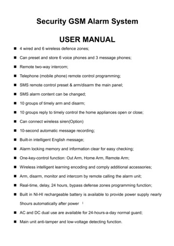
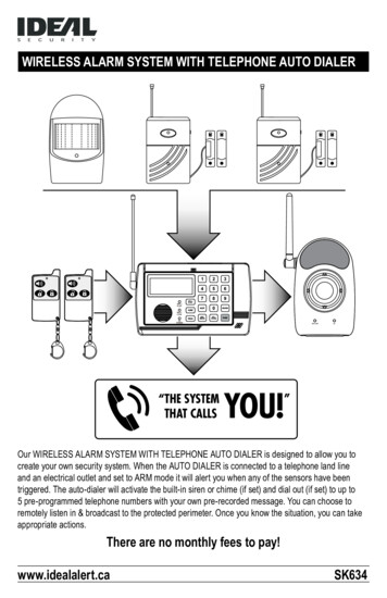
WIRELESS INDOOR/OUTDOOR SIREN & STROBE LIGHTDescription of Components1. Antenna2. Arm / Battery low / Trigger indication LED ( red )3. Strobe light4. AC indication LED ( green )5. Siren / Light function switch6. LEARN button7. Alkaline / Recharge switch8. DC Jack9. Entry delay switch10. Battery coverInstallation1372BAT.LOW5910DC 6VLEARN6AAAAAAAAAAAAALKALINE10SRECHARGE0S(Fig. 8)ALKALINE10SRECHARGE0S12InstallationInstall the CR2032 battery included into the remote control (Fig. 10). Remote controls for Arm, Disarm functions of the Telephone Dialer. Remote range from receiver is up to 25 meters (80 feet). The Remote Controls included with this kit are factory linked to the auto dialer.If the remote has to be moved closer to the receiver in order to function pleasereplace batteries. The battery life is about six months under normal use.0S8WIRELESS REMOTE CONTROLS310S4AC Remove the screws from the battery compartment cover (Fig. 8). Set the Entry delay (0 / 10 seconds) timer switch. Set the battery type switch.WARNING: Failure to choose the
WIRELESS ALARM SYSTEM WITH TELEPHONE AUTO DIALER Our WIRELESS ALARM SYSTEM WITH TELEPHONE AUTO DIALER is designed to allow you to create your own security system. When the AUTO DIALER is connected to a telephone land line and an electrical outlet and set to ARM mode it wi