Transcription
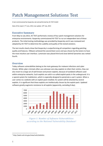
R2Sonic LLC Multibeam Training – The Patch TestMultibeam Calibration: The Patch Test1 IntroductionThe alignment of the Sonic 2024/2022 sonar head to the motion sensor and gyro is critical to theaccuracy of the determined depths. It is not possible to install the sonar head in exact alignmentwith the motion sensor and gyro to the accuracy required (x.xx ). If GPS time synchronization is notused, the latency of the position, as reported by the GPS, must also be measured during thecalibration. This being the case a multibeam calibration must be performed to measure the angularmisalignment between the Sonic 2024/2022 and the motion sensor and gyro and, if necessary, theposition latency; this is called the Patch Test.The patch test is performed with each new installation or whenever a sensor is moved. In the caseof an over‐the‐side mount, a large number of calibration computations need to be performed todetermine how well the pole goes back into the same position each time it is deployed. With morepermanent mounting arrangements, a minimum of 5 separate patch tests should be conducted inorder to derive a standard deviation that would indicate the accuracy of the derived values.The patch test involves collecting data over certain types of bottom terrain and processing the datathrough a set of patch test tools. There are two primary methods of processing the data that arecurrently used: an interactive graphical approach and an automatic, iterative surface match. Each ofthese techniques has strengths and weaknesses and the preferred approach is dependent on thetypes of terrain features available to the surveyor. All modern multibeam data collection softwarepackages contain a patch test routine. Please read the software manual for explicit informationregarding the requirements for that software’s patch test. The below criteria is, in general, the normfor a patch test.2 Orientation of the Sonic 2024/2022 Sonar HeadThe orientation of the sonar head must be known in order to convert the measured slant ranges todepths and to determine the position of each of the determined depths.Any error in the measured roll of theSonic 2024/2022 sonar head can causesubstantial errors in the conversion fromslant range to depth. A roll error of 1 on a 50 m slant range will cause a 0.6 merror in the resulting depth. Any error inthe measured pitch of the Sonic2024/2022 head will primarily have a detrimental effect on the accuracy of the positions that aredetermined for each slant range/depth.Figure 1: Sonic 2024/2022 axes of rotationA pitch error of 1 will cause an along‐track error in the position of 0.4 meter when the sonar headis 25 meters above the seabed.Page 1 of 10 2017, R2Sonic LLCC.W. Brennan, Chief Hydrographic Engineer‐R2Sonic
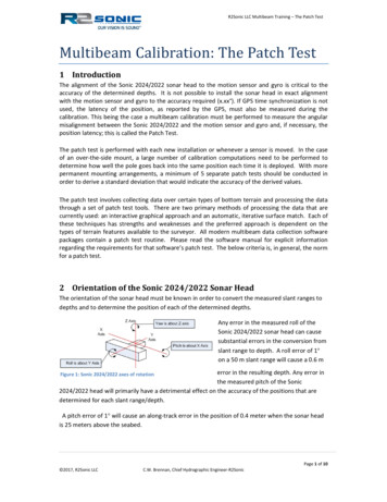
R2Sonic LLC Multibeam Training – The Patch Test3 Patch Test CriteriaThe patch test requires collecting sounding data over two distinct types of sea floor topography; aflat bottom is used for the roll computation whereas a steep slope or feature is used for the latency,pitch, and yaw data collection.Care must be taken that the sonar head covers the same area on both data collection runs, this maynot be the same as vessel position, especially with an over‐the‐side mount or if the sonar headrotated. Only the latency data collection requires a different speed from normal survey speed.The data collection for Latency, Pitch and Yaw should be done in as deep water as possible. This isparticularly true for the pitch computation due to the fact that in shallow water the angle of pitchmay not be easily determined due to a lack of resolution.3.1 Latency TestThe vast majority of installations will incorporate GPS time synchronisation and, as such, no latencyis expected in the GPS position. However, it is necessary to complete at least one or two latencytests to prove that the latency, for all practical purposes, is zero. Most patch test programs will notyield zero latency, but the derived value would be so small so as to constitute a practical zero.For the latency test, data is collected on a pre‐defined line up a steep slope or over a well‐definedobject (such as a rock or small wreck). The line is surveyed at survey speed up the slope, and thensurveyed again, in the same direction, but at a speed that should be half of the survey speed. If thevessel cannot make way at half survey speed then the fast run will need to be taken at a higherspeed than normal survey speed and this can influence the latency test due to squat or settlement.The main consideration is that one line should be twice the speed of the other.Figure 2: Latency Data collectionPage 2 of 10 2017, R2Sonic LLCC.W. Brennan, Chief Hydrographic Engineer‐R2Sonic
R2Sonic LLC Multibeam Training – The Patch Test3.2 Roll TestThe data collection for roll has to be over a flat sea floor. One line is surveyed twice, in reciprocaldirections and at survey speed.When the data, from the two data collections, are looked at inprofile, there will be two seafloors sloped in oppositedirections. Most patch test programs will go through a series ofiterations to determine when the difference between the twosurfaces is the smallest, and this is the roll offset.Figure 4: Roll data collectionsRoll is perhaps the most critical value in the patch test routine asan error in roll will result in an error in sounding depths.However, the computation to determine the roll misalignment is usually the easiest and mostconsistent.Figure 3: Roll data collectionDepth Error in MetresSounding Error due to 0.5 Roll Error in 20 metres ‐0.20‐0.40‐0.60Degrees from NadirGraph 1: Depth errors due to incorrect roll alignmentPage 3 of 10 2017, R2Sonic LLCC.W. Brennan, Chief Hydrographic Engineer‐R2Sonic
R2Sonic LLC Multibeam Training – The Patch Test3.3 Pitch TestThe pitch data collection is over the same type of sea floor as the latency data collection, i.e. steepslope or feature on the sea floor. One line is surveyed, twice, in reciprocal directions at surveyspeed. It is very critical that the sonar head passes over the same exact part of the slope on eachrun.A profile of the data will show two different slopes,which represent the reciprocal data collections. Thepatch test software goes through a series ofiterations of pitch angle corrections until thedifference between the two surfaces reaches a null.Whatever the angle of correction, which results inthe minima or null, that angle will be reported as thepitch misalignment.Figure 5: Pitch data collectionsA pitch error will result in a an along –track position error, which increases greatly with depthSounding Position Error (metres)Position Errors due to PitchAlignment Errors6541.0 Error30.75 Error20.5 Error10.25 Error00100200300400Water Depth (metres)Graph 2: Position errors as a result of pitch misalignment; error can be either negative or positivePage 4 of 10 2017, R2Sonic LLCC.W. Brennan, Chief Hydrographic Engineer‐R2Sonic
R2Sonic LLC Multibeam Training – The Patch Test3.4 Yaw TestThe yaw data collection and subsequent solving for the yaw offset is usually the most difficult of the4 tests that comprise a patch test. This is especially true if a slope is used for the yaw computation; afeature generally works much better. The reason for this is that the area that is used for thecomputation is not directly under the vessel, but in the outer beams and the slope may not beperfectly perpendicular in relation to the course of the vessel.For the Yaw data collection two parallel lines areused, with the vessel surveying in the samedirection on those lines. The lines are to be oneither side of a sea floor feature or over a slope.The lines should be approximately 2 – 3 timeswater depth in separation. A yaw error will resultin a depth position error, which increase with thedistance away from nadir.Figure 6: Yaw data collectionPosition Error with a Heading Error of 0.50 64Along‐track Position Error in MetresWater Depth2200 metres150 metres0‐80‐60‐40‐20020406080‐2100metre50 metre25 metres10 metres‐4‐6Angle from NadirGraph 3: Along track position error caused by 0.5 error in yaw patch testPage 5 of 10 2017, R2Sonic LLCC.W. Brennan, Chief Hydrographic Engineer‐R2Sonic
R2Sonic LLC Multibeam Training – The Patch TestPosition Error with a Heading Error of 1.0 108Along‐track Position Error in Metres6‐100Water Depth4200 metres2150 metres100metre0‐50‐2050‐410050 metre25 metres10 metres‐6‐8‐10Angle from NadirGraph 4: Along‐track position error caused by 1.0 error in yaw patch test error4 Solving for the Patch TestDepending on the data collection software that is employed and how it solves for the patch test,there will be a distinct order that the tests will be solved for, but this does not influence the datacollection for the patch test. In general, latency will be solved before pitch; roll will be solved forbefore yaw. It is not uncommon that a larger than expected error in one of the tests will make itnecessary to go back and resolve for all previous values. This can be the case with a large yaw offset,as this will influence to a greater degree the accuracy of the latency and pitch computations if doneusing a slope.The resultant patch test values are corrections that are entered in the data collection software andnot in the Sonic 2024/2022 software, as the values are used for process data.4.1 HistorySince the advent of commercial multibeam echosounders there has been the need to measurethe angular offsets between the multibeam sonar head and the auxiliary sensors that provideattitude and heading information. Another measurement is made to determine the latency, inthe GPS receiver. Multibeam data is collected that is used to determine (1) latency, (2) roll offset,(3) pitch offset and (4) heading or yaw offsetWhat has been developed is called the Patch Test; this is the multibeam calibration. During thedevelopment of the data collection criteria, for the Patch Test, there has only been a basicdescription for the manner of the data collection; providing little, if any, directions that wouldhelp create a high degree of confidence in the results of the various tests. This section willPage 6 of 10 2017, R2Sonic LLCC.W. Brennan, Chief Hydrographic Engineer‐R2Sonic
R2Sonic LLC Multibeam Training – The Patch Testaddress those very directions that will help create a highly accurate and statistically viableresult from the Patch Test.4.2 Basic data collection criteriaPatch test data collection does not have to be in any set order, but the order that the valuesare computed, in the data collection or processing software, will be in a distinct order.Normally, Latency is the first value that is computed, followed by Roll, Pitch and Yaw (orheading). The solving order is important, as will be seen below.4.3 Patch Test data collection error areasThere are many common errors, or mistakes, made during the patch test data collection.4.3.1PositioningThe accuracy of the positioning system is a common area where errors arise. DGPS has, at best,a variability of 0.50 metres, whereas RTK variability is 0.05metres.A recent article, in Hydro International (‘Stop Using DGPS’; Hydro International; Volume 16,Issue 7; Oct 2012) documents this issue very well.The article fully details the errors that can occur by using DGPS, instead of highly accuratepositioning for the Patch Test data collection. The error increases inversely with the waterdepth,i.e. the shallower the water, the larger the error that can be induced by using DGPS over moreaccurate positioning.However, many users do not have any better positioning capabilities than DGPS; how can theystill obtain valid patch test results without having centimetric accurate positioning? This is, inlarge part, what this paper is concerned with. However, even with centimetric position, thefollowing should be followed.4.3.2Feature chosen for testWhere at all possible, for latency, pitch and heading data collection, a feature should be usedrather than a slope. Slopes tend to be too variable as opposed to a well‐defined feature such asa wreck, rock outcrop or pipeline.One of the other issues, with using a slope, is that many times the shallow end of the slopedoes not allow sufficient area or depth for the vessel to come about and line up for thereciprocal run; this does not allow sufficient time for the motion sensor to settle down nor forthe helmsman to find a steady course.It has been found that when using a slope, for the pitch calibration, that the heading angularoffset can have a large influence. If the sonar head does not track exactly the same route, upand down the slope, the heading offset will affect the pitch angular result.Page 7 of 10 2017, R2Sonic LLCC.W. Brennan, Chief Hydrographic Engineer‐R2Sonic
R2Sonic LLC Multibeam Training – The Patch Test4.3.3Water depthThe deeper the water, the better the result. In shallow water, DGPS wobble creates more,relatively severe, position errors. A corollary to this is that the subtended angle is larger inshallow water, which can blur the definition of the object used, be it a feature or slope. Theshallower the water, the larger the subtended angle; the deeper the water, the smaller thesubtended angle and, therefore, the better the definition of the object or slope.4.3.4Use predefined survey linesThe most important positioning issue is having the sonar head pass over the same exactlocation in both of the survey data collections. This is especially true when using a highlyvariable slope. One way to assist the helmsman is to give the helmsman a defined line tonavigate by. Just trying to go over the same track, without a line reference, does not work, asit is the sonar head that has to pass over the same exact point; this accuracy cannot beobtained just by using the grid display to steer the vessel.When setting up the survey software, make sure that the sonar head is the steered referencefor all offline measurements. It does no good to have the vessel on the survey line, if the sonaris mounted on the side of the vessel; it is the sonar that should be on the survey line.4.3.5SpeedWhen doing the latency data collection, the fast run should be at survey speed where, if there issquat or settlement, it should have been previously measured and can be applied. Many times,the fast run survey line is at a speed that is greater than the normal survey speed and inducesunknown squat and settlement errors into the computation.4.3.6Vessel line upIn order for the angular measurement to be accurate, the vessel should have sufficient time tocome on line and allow the motion sensor to ‘settle down’. Sufficient lead/run in should alsobe allowed in order for the helmsman to find the proper heading so that vessel can maintain asstraight a course as possible.4.3.7Pole variabilityThe other issue, which is often overlooked, is the variability in the repeat position of adeployable hydrophone pole. With any moveable mounting arrangement the pole should berecovered and redeployed a few times, during data collection, to determine if it does, indeed,go back into the same aspect every time that it is deployed. (It is a good idea, after redeployingthe head, to do a few figure 8 manoeuvres.)Page 8 of 10 2017, R2Sonic LLCC.W. Brennan, Chief Hydrographic Engineer‐R2Sonic
R2Sonic LLC Multibeam Training – The Patch Test5 Improving the Patch Test and Patch Test resultsThe previous section describes areas that should be addressed to improve the results of thepatch test when collecting the data. Further improvement will come with the number ofdata collections and the manner in which the patch test is computed.5.1 Need to collect sufficient dataToo many times, surveyors will collect just a few lines of data for each test. One of the majorissues, detailed above, is the variability of the position accuracy of DGPS. Another issue,detailed above, is the steering of the vessel during the data collection and the relationship ofthe sonar head to the feature or slope on each data collection.In order to overcome the variability of the DGPS positioning and vessel steering, it followsthat the more tests that are performed, the greater will be the reliability of the test results.Below, is an example of a multibeam calibration, which included five data collections for h mean with erroneous value ‐1.16 (SD 0.58); without erroneous value of ‐2.16 ‐0.91 (SD 0.13) Yawmean with erroneous value 1.19 (SD 0.61); without erroneous value of 2.26 0.92 (SD 0.08)Consider the above patch test and what the result would have been if only two collectionswere made and those were the ones that contained the highlighted values, which canclearly be seen to be outside of the trend. Having more data to work with, a more reliableresult can be achieved.The more data collected, the more evident will be any out of trend values that may reflect aDGPS wobble, a steering issue, or variability of the positioning of the pole. Enough datashould be collected to provide a reliable statistical result, i.e. mean and standard deviation.Collecting enough data to compute six of each test, allows the exclusion of any one ‘out oftrend’ result to yield a mean and standard deviation derived from five computations; thiswould be a statistically viable sampling.Page 9 of 10 2017, R2Sonic LLCC.W. Brennan, Chief Hydrographic Engineer‐R2Sonic
R2Sonic LLC Multibeam Training – The Patch Test5.2 Individually solving valuesNo matter what the solving order may be, each value should be computed independently. Alltests should be based on the mean of the previous test(s).It is important to understand why a certain solving order is used in all survey software. Eachcomputation is based on the previous test result. This is the reason that latency is computedbefore pitch and roll is computed before heading; the primary test (latency or roll) has a largeinfluence on the result for the secondary test (pitch and heading). The roll computation canalso have an influence on the pitch computation, primarily if the position of the sonar head, ofthe reciprocal runs, was not coincident. The heading offset will also have an influence on thepitch computation for the same reason.Generally, multibeam surveys are conducted with very accurate time synchronisation using GPStime and the Pulse Per Second. In this case, the latency test is used to prove the lack of latencyor that is sufficiently small enough so as to be of no consequence. Using accurate timing, it isnot necessary to collect more than two latency collections. This paper will concentrate on theangular offset computations. However, if accurate timing is not used there should be the samenumber of collections as with the other tests.With a good number of individual tests, solve for one computation (i.e. only roll) and derive amean and standard deviation for that one test. Determine if the standard deviation is withinacceptable accuracy requirements, then use that derived mean to solve for the nextcomputation (i.e. pitch). As an example, using the results on page 7, the first step would be tosolve for Roll first, derive a Roll mean and then use that mean in all of the Pitch computations.Find the mean and standard deviation for Pitch. Use the mean Roll and Pitch values todetermine the Heading offset.In the above example, the roll mean, of the five tests, is 0.74 , with a standard deviation (δ) of0.01 . The roll mean would now be used when determining the value for pitch. Use the rollmean and solve all of the pitch computations; the pitch mean is ‐0.91 (excluding the out ofnorm value), δ 0.13 . The roll and pitch computed means are now used to solve for theheading offset. The solved heading offset is 0.92 , δ 0.08 .If the heading offset had been 1.5 or greater, it would be advisable to re‐compute the pitchoffset, using the computed heading offset value. This is due, again, to the fact th
rotated. Only the latency data collection requires a different speed from normal survey speed. The data collection for Latency, Pitch and Yaw should be done in as deep water as possible. This is particularly true for the pitch computation due to the fact that in shallow water the angle of pitch