Transcription
Aurora's Technological and Research InstituteStrength of MaterialsSTRENGTH OF MATERIALSLAB MANUALB.Tech II Year – I SEMNAME:ROLL NO:BRANCH:DEPARTMENT OFCIVIL ENGINEERINGAurora’s Technological & Research InstituteParvathapur, Uppal, Hyderabad-98Department of Civil1
Strength of MaterialsAurora's Technological and Research InstituteSTRENGTH OF MATERIALS LABCONTENTSSl.No.ExperimentPage NoEvaluation of Laboratory Marks Internal1Evaluation of Laboratory Marks End Exams3Lab code4Introduction51.Hardness / Rockwell Hardness Test6-122.Izod & Charpy Impact Test13-153.Bending Test On A Simply Supported Beam16-214.Bending Test On A Cantilever Beam22-265.Spring Test27-316.Torsion Test32-357.Tension Test36-438.Shear test44-449.Compressive strength on concrete45-4610.Verification of maxwells reciprocal theorem47-4811.Continuous beam deflection test49-5012.Effect of loading and unloading beyond the elastic limit51-52Department of Civil2
Strength of MaterialsAurora's Technological and Research InstituteEvaluation of Laboratory Marks for II Year (Internal Exams)1.The internal lab examination schedules will be given by the Examination Branch.2.During a year there will be three lab exams and each exam will be evaluated for 25marks.3.Average of three lab exams will be the final internal lab exam marks.4.First laboratory exam will be conducted on First 1/3 of the total number of experiments,Second Laboratory Exam will be conducted on the Second 1/3 of experiments and theThird Laboratory Exam will be conducted on the last 1/3 of experiments.The evaluation is as followsI.Continuous evaluationII.Internal Laboratory Exam-15 marks10 marksI.Continuous Evaluationa)Day to day evaluation10 marksEach experiment / program will be evaluated for 10 marks.The splitting of marks is as followsb)i)Attendance2 marksThe student should attend the lab regularly; if he/she is absent he/she will belosing 2 marks.ii)Experiments / program and observationThe student should complete the program / experiment within the assigned timeotherwise he / she will be losing 2 marks.iii)Experiment result will carry 4 marks.iv)Record 2 marksStudent must submit the record in the next lab session.v)Average marks of the Half of the experiments will be considered for day to dayevaluation for 10 marks separately for lab examination one and two.Lab knowledge Test (Quiz) 5 marks1.A quiz will be conducted along with the internal lab exam and schedule will begiven separately.2.The quiz will be conducted for 20 minutes. The quiz contains 20 questions of typemultiple choice. Each question carrying 0.25 marks.Department of Civil3
Strength of MaterialsAurora's Technological and Research InstituteII.Internal laboratory examination-10 marksa)ExamThe Splitting of marks as followsi) Experiments / Program write upii) Result and Graphs-7 marks-4 marks3 marksViva Voce-3 marks1. The internal lab examination duration-2 hoursb)2. Every student will be given programs / experiments in the internal lab exam.In case the student wishes to change the programs / experiments 1 markwill be deducted. A time slot of 45 minutes is given for write up ofprograms / experiments.3. The student is expected to complete the assigned program / experiment within1 hour and the remaining 15 minutes will be utilized for viva voceexamination.5.There shall be no supplementary exams in case the student fails to attend internal lab andquiz exam as per schedule.Department of Civil4
Strength of MaterialsAurora's Technological and Research InstituteEvaluation of Laboratory Marks (End exams)1.The external lab examination schedules will be given by the Examination Branch.2.Duration of External lab examinations3.Exam will be evaluated for 50 Marks-3 HoursThe Splitting of marks is as followsI.Experiment write-up / Program with algorithm-10 marksII.Experiment Setup / Program execution-10 marksIII.Result-10 marksIV.Viva –Vocea) Written Vivab) Oral Viva-20 marks10 marks10 marksWritten Viva–Voce Exam will be consisting of 10 questions of short answer type and fillin the blanks. Each question will carry equal marks and allotted time is 15 minutes.Department of Civil5
Aurora's Technological and Research InstituteStrength of MaterialsLAB CODE1.Students should report to the labs concerned as per the timetable.2.Students who turn up late to the labs will in no case be permitted to perform theexperiment scheduled for the day.3.After completion of the experiment, certification of the staff in-charge concerned in theobservation book is necessary.4.Students should bring a notebook of about 100 pages and should enter thereadings/observations/results into the notebook while performing the experiment.5.The record of observations along with the detailed experimental procedure of theexperiment performed in the immediate previous session should be submitted andcertified by the staff member in-charge.6.Not more than three students in a group are permitted to perform the experiment on a setup.7.The group-wise division made in the beginning should be adhered to, and no mix up ofstudent among different groups will be permitted later.8.The components required pertaining to the experiment should be collected from Lab- incharge after duly filling in the requisition form.9.When the experiment is completed, students should disconnect the setup made by them,and should return all the components/instruments taken for the purpose.10.Any damage of the equipment or burnout of components will be viewed seriously eitherby putting penalty or by dismissing the total group of students from the lab for thesemester/year.11.Students should be present in the labs for the total scheduled duration.12.Students are expected to prepare thoroughly to perform the experiment before coming toLaboratory.13.Procedure sheets/data sheets provided to the students’ groups should be maintainedneatly and are to be returned after the experiment.14.DRESS CODE:Boys - Formal white shirt neatly tucked in, and white trousers, white / black / brown / tanshoes and belt, I-cards worn round neckGirls - Formal white Salwar Kameez, white / black / brown / tan shoes, I-cards wornround neckDepartment of Civil6
Strength of MaterialsAurora's Technological and Research InstituteINTRODUCTIONMaterials which we come across may be classified into elastic, plastic and rigid maerials. Anelastic material undergoes a deformation when subjected to an external loading such that thedeformation disappears on the removal of loading. A plastic material undergoes a continuousdeformation during the period of loading and the deformation is permanent and the material doesnot regain its original dimensions on the removal of the loading. A rigid material does notundergo any deformation when subjected to an external loading.In practice no material is absolutely elastic nor plastic nor rigid. We attribute these propertieswhen the deformations are within certain limits. Generally we handle a member in its elasticrange. Structural members are all generally designed so as to remain in the elastic conditionunder the action of the working loads.A material when subjected to an external load system undergoes a deformation. It becomesnecessary to study the deformations in order to determine the conditions under which failure mayoccur. The ability of a part or element of a structure to resist failure by virtue of its strength.The ability to resist deformation is called stiffness. The material will have the ability to offer thenecessary resistance when the deformation is with in a certain limit. A loaded member remainsin equilibrium when the resistance offered by the member against the deformation and theapplied load are in equilibrium. When the member is incapable of offering the necessaryresistance against the external forces, the deformation will continue leading to the failure of themember.Because of the complexity involved certain simplifying assumptions are made in strengthcalculations:1. The material of the body has a solid continuous structure.2. Within the limits of the part of the body the material is homogeneous and isotropic i.e., ithas identical properties in all directions at all points3. There are no internal forces in a body prior to loading4. The effect of the system of forces acting on a body is equal to the sum of the effects ofthese same forces applied in succession and in any order. This is the principle of superimposition.5. At points in a body sufficiently away from the points of application of loads, internalforces are independent of the manner in which the loads are applied. This is known asSaint Venant Principle. Theoretical investigations show that points more than 1.5-2 timesthe greatest linear dimension of the area of load transmission from the region of loading adistributed load can be replaced by a concentrated load. Thus the principle enables adistributed load replaced by a point load over a small area.Department of Civil7
Aurora's Technological and Research Institute1.Strength of MaterialsROCKWELL HARDNESS TEST1.AIM: To determine the Rockwell Hardness of a given test specimenII.APPARATUS: Rockwell Hardness testing machine, Test specimen.III.THEORY:HARDNESS-It is defined as the resistance of a metal to plastic deformation againstIndentation, scratching, abrasion of cutting.The hardness of a material by this Rockwell hardness test method is measured by thedepth of Penetration of the indenter. The depth of Penetration is inversely proportional to thehardness. Both ball or diamond cone types of indenters are used in this test. There are threescales on the machine for taking hardness readings. Scale “A” with load 60 kgf or 588.4 N anddiamond indenter is used for performing tests on thin steel and shallow case hardened steel.Scale “B” with load 100 kgf or 980.7 N and 1.588 mm dia ball indenter is used for performingtests on soft steel, malleable iron, copper and aluminum alloys.First minor load is applied to over come the film thickness on the metal surface. Minorload also eliminates errors in the depth of measurements due to spring of the machine frame orsetting down of the specimen and table attachments.The Rockwell hardness is derived from the measurement of the depth of the impressionEP Depth of penetration due to Minor load of 98.07 N.Ea Increase in depth of penetration due to Major load.E Permanent increase of depth of indentation under minor load at 98.07 N even afterremoval of Major load.This method of test is suitable for finished or machined parts of simple shapes.Department of Civil8
Strength of MaterialsAurora's Technological and Research InstituteIV.PROCEDURE:1.Select the load by rotating the Knob and fix the suitable indenter.2.Clean the test-piece and place n the special anvil or work table of the machine.3.Turn the capstan wheel to elevate the test specimen into contact with the indenterpoint.4.Further turn the wheel for three rotations forcing the test specimen against theindenter. This will ensure that the Minor load of 98.07 N has been applied5.Set the pointer on the Scale dial at the appropriate position.6.Push the lever to apply the Major load. A Dash Pot provided in the loadingmechanism to ensure that the load is applied gradually.7.As soon as the pointer comes to rest pull the handle in the reverse directionslowly. This releases the Major, but not Minor load. The pointer will now rotatein the reverse direction.8.The Rockwell hardness can be read off the scale dial, on the appropriate scale,after the pointer comes to rest.V.OBSERVATIONS:Material of test piece Thickness of test piece Hardness Scale used Minor Load Major Load Test No.1234Hard ness valueVI.PRECAUTIONS:1.For testing cylindrical test specimen, use V-type platform.2.Calibrate the machine occasionally using standard test blocks.Department of Civil9
Aurora's Technological and Research Institute3.Strength of MaterialsFor thin metal prices place another sufficiently thick metal piece between the testspecimen and the platform to avoid any damage which may likely occur to theplatform.4.After applying Major load, wait for sometime to allow the needle to come to rest.The waiting time vary from 2 to 8 seconds.5.The surface of the test piece should be smooth and even and free from oxide scaleand foreign matter.6.Test specimen should not be subjected to any heating or cold working.7.The thickness of test piece or of the layer under test should be at least 8 times thepermanent increase of depth of “E”.8.The distance between the centers of two adjacent indentation should be at least 4indentation to the edge of the test piece should be at least 2.5 times the diameterof the indentation.VII.VIVA QUESTIONS:3.Define Hardness.4.Applications of Rockwell Hardness A – Scale, B-Scale, C-Scale.5.Type of Indentor used in the Three Different Scales of Rockwell Hardness Test.6.Different Types of Hardness Testing Methods.7.Size of the Ball to be used in Ball Indentor of Rockwell Hardness Test.8.Diameters of the different Balls used in Brinell Hardness Test.9.Selection of Load in Brinell Hardness Test.10.Selection of Load in Rockwell Hardness Test.Department of Civil10
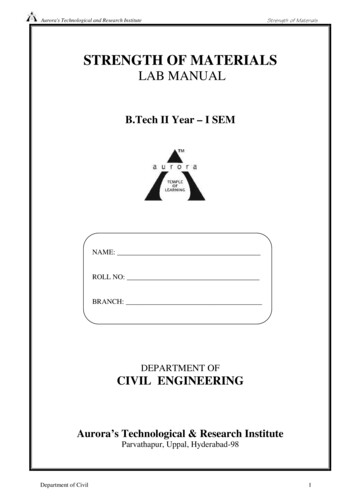
Aurora's Technological and Research InstituteStrength of MaterialsFigure: Hardness Testing MachineDepartment of Civil11
Aurora's Technological and Research InstituteStrength of MaterialsBRINELL HARDNESS TESTI.AIM: To determine the Brinell hardness of the given test specimen.II.APPARATUS: Brinell hardness machine, test specimen. Brinell MicroscopeIII.THEORY:INDENTATION HARDNESS-A number related to the area or to the depth of theimpression made by an indenter or fixed geometry under a known fixed load.This method consists of indenting the surface of the metal by a hardened steel ball ofspecified diameter D mm under a given load F(kgf) and measuring the average diameter d mm ofthe impression with the help of Brinell microscope fitted with a scale. The Brinell hardness HBis defined, as the quotient of the applied force F divided by the spherical area
Lab code 4 Introduction 5 1. Hardness / Rockwell Hardness Test 6-12 2. Izod & Charpy Impact Test 13-15 3. Bending Test On A Simply Supported Beam 16-21 4. Bending Test On A Cantilever Beam 22-26 5. Spring Test 27-31 6. Torsion Test 32-35 7. Tension Test 36-43 8. Shear test 44-44 9. Compressive strength on concrete 45-46 10. Verification of .