Transcription
15-2: Power and Electromagnetic Side-Channel Attack Resilient SecureAES Core utilizing Galvanic Isolation approach with Integrated ChargePump based Power ManagementMeizhi Wang, Shanshan Xie, Ping Na Li, Aseem Sayal, Ge Li, Vishnuvardhan V. Iyer,Aditya Thimmaiah, Michael Orshansky, Ali E. Yilmaz, and Jaydeep P. KulkarniECE Department, University of Texas at AustinE-mail: wang.mz@utexas.edu, jaydeep@austin.utexas.edu28 April 2021Circuit Research Labhttps://sites.utexas.edu/CRL/
Outline Side Channel Analysis (SCA) Prior Work: Power SCA resilient approaches Motivation: Susceptibility to the ground bounce Proposed Work- Principle of Galvanic Isolation (GI)- Proposed GI-AES architecture Test-chip measurement- Die photo, Measurement summary- Power SCA- EM SCA Comparison & Conclusion2
Outline Side Channel Analysis (SCA) Prior Work: Power SCA resilient approaches Motivation: Susceptibility to the ground bounce Proposed Work- Principle of Galvanic Isolation (GI)- Proposed GI-AES architecture Test-chip measurement- Die photo, Measurement summary- Power SCA- EM SCA Comparison & Conclusion3
Side Channel Analysis Easy physical access Inexpensive High successful ratehttps://www.keirex.com/e/Kti072 SecurityMeasure e.html4
Outline Side Channel Analysis (SCA) Prior Work: Power SCA resilient approaches Motivation: Susceptibility to the ground bounce Proposed Work- Principle of Galvanic Isolation (GI)- Proposed GI-AES architecture Test-chip measurement- Die photo, Measurement summary- Power SCA- EM SCA Comparison & Conclusion5
Prior Work: Power SCA resilient approaches Constant Current Signature Randomized Current Signature6
Prior Work: Power SCA resilient approaches(a) Constant Current SignatureIIN- (a) Switch Capacitor Current EqualizerΦ2VOUTIOUTVIN Φ1Φ3VREFCCL Randomized Current Signature7
Prior Work: Power SCA resilient approachesIIN- (a) Switch Capacitor Current Equalizer(b)(a) Constant Current SignatureΦ2IINIOUTVIN Φ1ControlΦ3VREFC- (b) Shunt RegulatorVINVOUTVOUTCLIBLEEDVTARGETCLIOUT Randomized Current Signature8
Prior Work: Power SCA resilient approaches(b)(a) Constant Current SignatureIIN- (a) Switch Capacitor Current EqualizerΦ2IINIOUTVIN Φ1ControlΦ3VREFCVOUTCLIBLEEDVTARGET- (b) Shunt Regulator Randomized Current SignatureVINVOUTCLIOUT(c)VIN- (c) Low Drop Out RegulatorIINVREFVOUTCLIOUT9
Prior Work: Power SCA resilient approaches(b)(a) Constant Current SignatureIIN- (a) Switch Capacitor Current EqualizerΦ2VINVOUTIINIOUTVIN Φ1Φ3VREFCVOUTCLIBLEEDVTARGET- (b) Shunt Regulator Randomized Current Signature(c)IOUTVINIINVREFLΦ1VOUTVOUT- (d) Buck ConverterCL(d)VIN- (c) Low Drop Out RegulatorControlCLIOUTΦ2CIOUTCL10
Prior Work: Power SCA resilient approaches(b)(a) Constant Current SignatureIIN- (a) Switch Capacitor Current EqualizerΦ2VINVOUTIINIOUTVIN Φ1Φ3VREFCVOUTCLIBLEEDVTARGET- (b) Shunt Regulator Randomized Current Signature(c)VINΦ1LΦ1CLVOUTVINVOUTVOUT- (d) Buck ConverterIOUTIINIINVREFCL(e)(d)VIN- (c) Low Drop Out RegulatorControlIOUTΦ2CCLIOUTIOUTΦ2CFLYΦ2CLΦ1- (e) Switched-Capacitor Voltage Regulator11
No VSS pins areisolated in theseapproachesPrior Work: Power SCA resilient approaches(b)(a) Constant Current SignatureIIN- (a) Switch Capacitor Current EqualizerΦ2VINVOUTIINIOUTVIN Φ1Φ3VREFCVOUTCLIBLEEDVTARGET- (b) Shunt Regulator Randomized Current Signature(c)VINΦ1LΦ1CLVOUTVINVOUTVOUT- (d) Buck ConverterIOUTIINIINVREFCL(e)(d)VIN- (c) Low Drop Out RegulatorControlIOUTΦ2CCLIOUTIOUTΦ2CFLYΦ2CLΦ1- (e) Switched-Capacitor Voltage Regulator12
Outline Side Channel Analysis (SCA) Prior Work: Power SCA resilient approaches Motivation: Susceptibility to the ground bounce Proposed Work- Principle of Galvanic Isolation (GI)- Proposed GI-AES architecture Test-chip measurement- Die photo, Measurement summary- Power SCA- EM SCA Comparison & Conclusion13
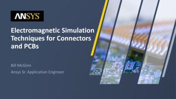
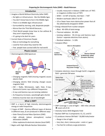
(a)(b)CLK 100MHzV(mV)Motivation: Susceptibility to the ground bounce50Vss bouncetraces of the finalencryption roundCryptoCorecorrelationtime(ns)Correct keyIncorrect keyMTD 6000traces Ball grid array (BGA) pins near to crypto core may reveal circuit VSS bounce that canbe used for side-channel analysis14
Simulation flow𝑁e No. of encryptions𝑁n No. of VSS nodes15
V(mV)50 Vss bouncetraces of the finalencryption roundSimulation results on a 128-bit AES computing core(b)V(mV)CLK 100MHz50 Vss bouncetraces of the finalencryption roundCorrect keyIncorrect keyMTD 6000tracestime(ns)correlationcorrelationtime(ns) Implement a 128b AdvancedEncryptionCorrect keystandard (AES) coreIncorrect key Simulated VSS bounce waveforms forcorrelation attack Correlation attack shows key byte 1is revealed using 6000 tracesMTD 6000traces16
Outline Side Channel Analysis (SCA) Prior Work: Power SCA resilient approaches Motivation: Susceptibility to the ground bounce Proposed Work- Principle of Galvanic Isolation (GI)- Proposed GI-AES architecture Test-chip measurement- Die photo, Measurement summary- Power SCA- EM SCA Comparison & Conclusion17
Principle of Galvanic Isolation (GI) Isolates two electrical systems, preventing direct current flow and breaking ground loopsbetween two circuits.N:1 Transformer:- Primary (input) side potentially lethal transientvoltages and currents- Secondary side is completely isolated for safetyPrimarySecondaryTransformer: Isolatedenergy transfer18
Principle of Galvanic Isolation (GI) Isolates two electrical systems, preventing direct current flow and breaking ground loopsbetween two circuits.N:1 Transformer:- Primary (input) side potentially lethal transientvoltages and currents- Secondary side is completely isolated for safetySecondaryPrimaryTransformer: Isolatedenergy transfer- Flyback converter:- Inductor based Galvanic Isolation topology- Protecting low voltage devices from highvoltages transientsDVOUTCCLN:1VINFlyback converter19
Outline Side Channel Analysis (SCA) Prior Work: Power SCA resilient approaches Motivation: Susceptibility to the ground bounce Proposed Work- Principle of Galvanic Isolation (GI)- Proposed GI-AES architecture Test-chip measurement- Die photo, Measurement summary- Power SCA- EM SCA Comparison & Conclusion20
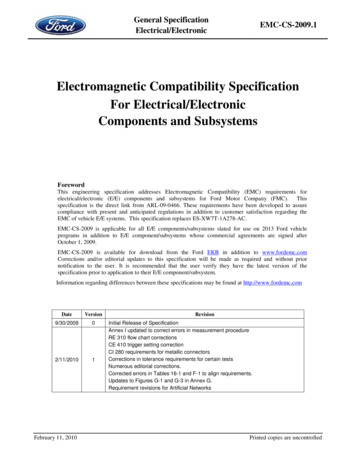
Proposed GI AES Apply capacitor based Galvanic Isolationtopology to minimize ground bouncesusceptibilityGalvanic IsolationExternalPower Domain Primary side: external power domainL1GND1L2GND2Crypto LogicCompute Domain Secondary side: crypto core powerdomain21
Proposed GI AES Apply capacitor based Galvanic Isolationtopology to minimize ground bouncesusceptibilityGalvanic IsolationExternalPower Domain Primary side: external power domain Scan chain InterfacePower management unit Secondary side: crypto core powerdomainL1L2GND1VCCGND2Crypto LogicCompute DomainVTOPDataScan Chain InterfacePower Management UnitVSSControlCapacitorBank128 bitAESCoreVBOT22
Galvanic isolation decouples AESengine compute domain andexternal power domain completelyProposed GI AES Apply capacitor based Galvanic Isolationtopology to minimize ground bouncesusceptibilityGalvanic IsolationExternalPower Domain Primary side: external power domain Scan chain InterfacePower management unit Secondary side: crypto core powerdomain Capacitor bankA 128-bit AES coreL1L2GND1VCCGND2Crypto LogicCompute DomainVTOPDataScan Chain InterfacePower Management UnitVSSControlCapacitorBank128 bitAESCoreVBOT23
Proposed GI AES 3D illustration:3D illustration of AES in deepN-well and capacitor bank,PMU and scan chain interface- AES in deep N-well, isolated Psubstrate, powered by 𝑉𝑇𝑂𝑃 𝑉𝐵𝑂𝑇- Capacitor bank (*2 layers drawn forillustration purpose)- PMU and scan chain interface*MoM capacitors (only two metal layers areshown for illustration purpose)24
GI-AES Architecture: System overview25
GI-AES Architecture: Main blocksScan chain Scan chain interface for data exchanging26
GI-AES Architecture: Main blocksAES Engine A 128b AES Engine for data encryption Operating in 𝑉𝑇𝑂𝑃 /𝑉𝐵𝑂𝑇 power domain27
GI-AES Architecture: Main blocksCapacitorBank Capacitance based galvanic isolation Power AES in 𝑉𝑇𝑂𝑃 /𝑉𝐵𝑂𝑇 domain during encryption28
GI-AES Architecture: Main blocksPMU Control capacitor bank to maintain functional 𝑉𝑇𝑂𝑃 /𝑉𝐵𝑂𝑇 voltage range29
GI-AES Architecture: Design techniques111 Header and footer transistors: decouple 𝑉𝑇𝑂𝑃 /𝑉𝐵𝑂𝑇 rail from VCC/VSS rail Isolate the external and the internal power domain (AES).30
GI-AES Architecture: Design techniques22 Deep N well: covering the AES engine, isolating the local substrateAES ground is completely isolated31
GI-AES Architecture: Design techniques33 Capacitor banks: charge pump based voltage doubler circuit32
GI-AES Architecture: Design ABS3B1S3AB3S3A2S2B2S3B23 𝐶0 as the main capacitor and multiple smaller capacitor pairs Multi-stage voltage doubler circuit33
GI-AES Architecture: Design Precharge phase: Header and footer are connected All capacitors are fully charged to VCC/VSSVtopVdelta VcritVbotVSSBoost-1Boost-2CS3 Three operation phases: Precharge, Compute, Charge sharing34
GI-AES Architecture: Design techniquesPrechargeComputeComputeCLKVCCVtopVdelta VcritVbotVSSChargesharePrecharge phase: Header and footer are connected All capacitors are fully charged to VCC/VSSCompute phase: Header and footer are disconnected Capacitor bank powers AES Core Voltage boostings are triggered sequentiallyBoost-1Boost-2CS3 Three operation phases: Precharge, Compute, Charge sharing35
GI-AES Architecture: Design techniquesPrechargeComputeComputeCLKVCCVtopVdelta VcritVbotVSSBoost-1Boost-2CSChargesharePrecharge phase: Header and footer are connected All capacitors are fully charged to VCC/VSSCompute phase: Header and footer are disconnected Capacitor bank powers AES Core Voltage boostings are triggered sequentiallyCharge sharing Discharge capacitors to mask real chargeconsumption3 Three operation phases: Precharge, Compute, Charge sharing36
GI-AES Architecture: Design techniques44 Dual rail sense amp: trigger the next boosting stage if 𝑉𝑇𝑂𝑃 and 𝑉𝐵𝑂𝑇 are below 𝑉𝑟𝑒𝑓 Current signature remain the same in each cycle, not prone to SCA37
GI-AES Architecture: Design techniques55 Charge share transistor: discharges all the capacitors to certain predefined voltage. Uniform on 𝑉𝑇𝑂𝑃 and 𝑉𝐵𝑂𝑇 before each precharge cycle38
GI-AES Architecture: Design techniques66 Dual rail sense amp (uniform current signature) as a level shifter to transfer signalfrom voltage level VTOP/VBOT to voltage level VCC/VSS .39
Outline Side Channel Analysis (SCA) Prior Work: Power SCA resilient approaches Motivation: Susceptibility to the ground bounce Proposed Work- Principle of Galvanic Isolation (GI)- Proposed GI-AES architecture Test-chip measurement- Die photo, Measurement summary- Power SCA- EM SCA Comparison & Conclusion40
Die photo, Measurement Summary Technology: 40 𝑛𝑚 CMOS Power@1.2𝑉: 23 𝑚𝑊 Area(𝑚𝑚2 ): AES CoreLevel ShifterPMUCapacitor SwitchesCapacitor BankTotal Area0.0320.007950.001360.004290.1780.223641
Outline Side Channel Analysis (SCA) Prior Work: Power SCA resilient approaches Motivation: Susceptibility to the ground bounce Proposed Work- Principle of Galvanic Isolation (GI)- Proposed GI-AES architecture Test-chip measurement- Die photo, Measurement summary- VSS bounce SCA- EM SCA Comparison & Conclusion42
VSS Bounce SCA Measurement: SetupPower supplyOscilloscopeTest-chip andMicrocontrollerFunctionGenerator VSS bounce waveforms and cipher text collected by the oscilloscope are used for SCA43
VSS Bounce SCA: Stand alone charge pump circuitCharge pump design architecture8μs1.2VS1A1S3A1S2A1S1B1C0S1A2 cope measurement show successful multiple voltage boosting44
VSS Bounce SCA: Flow chart & Timing diagramGI AES flow chartGI AES timing diagram & Vtop Vbot T2BOOST1AES CoreCLK23 6Key ReadyData ReadyAES BusyCLK56 major steps in one GI AES operation and successful 𝑉𝑇𝑂𝑃 /𝑉𝐵𝑂𝑇 boostings aredemonstrated in the oscilloscope measurements45
VSS Bounce SCA MeasurementBaseline AESVSS1VSS2VSS1VSS3VSS4VSS4GI AESVSS1VSS2VSS2VSS3VSS4VSS320nsAES Core CLKAES Busy100mV25nsAES Core CLKAES Busy Four randomly located VSS nodes for ground bounce monitoring46
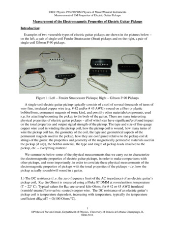
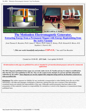
VSS Bounce SCA: Correlation attackCorrelation attack results Target on the last encryption roundMTD 5000tracescorrelationcorrelation The correct key has a distinct highcorrelation value.(a) Baseline AEScorrelation Baseline AES Key Byte 1 is revealed with5000 traces.(b) GI AES1.47Xkey guessesThe correct key is not yet foundafter 3 millions traces by CPAtracesCorrect keyIncorrect key47
VSS Bounce SCA: Correlation attackCorrelation attack results Target on the last encryption roundMTD 5000traces The secret key is not revealed within 3million traces Improving power SCA resilience by 600Xcorrelation GI AES :correlation The correct key has a distinct highcorrelation value.(a) Baseline AEScorrelation Baseline AES Key Byte 1 is revealed with5000 traces.(b) GI AES1.47Xkey guessesThe correct key is not yet foundafter 3 millions traces by CPAtracesCorrect keyIncorrect key48
time (ns) t-value time (ns)leakage assessment (TVLA)VSS Bounce SCA: Test vector t-value Run encryption on two data sets, each containing 20,000 fixed plaintexts and20,000 random plaintexts.Time domain t-value frequency (MHz)frequency (MHz)time (ns) t-value GI AES reduces max t-value under 4.5threshold value Improving TVLA results by 6.5X in timedomain49
t-value VSS Bounce SCA: Test vector leakage assessment (TVLA) t-value time (ns) t-value time (ns)time domain(ns)Frequency t-value GI AES reduces max t-value under 4.5threshold value Improving TVLA results by 6.5X in timedomain t-value t-value Time domainfrequency (MHz)time (ns)frequency (MHz) Run encryption on two data sets, each containing 20,000 fixed plaintexts and20,000 random plaintexts.frequency (MHz) GI AES reduces max t-value under 4.5threshold value Improving TVLA results by 25X in requencydomain50 t-value t-value
Outline Side Channel Analysis (SCA) Prior Work: Power SCA resilient approaches Motivation: Susceptibility to the ground bounce Proposed Work- Principle of Galvanic Isolation (GI)- Proposed GI-AES architecture Test-chip measurement- Die photo, Measurement summary- Power SCA- EM SCA Comparison & Conclusion51
EM SCA Measurement SetupOscilloscopeMATLABEM Probewith holderTest-chip andMicrocontroller The EM SCA attack uses a 10-mm H-field probe 1-mm above the package.52
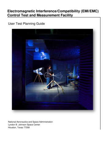
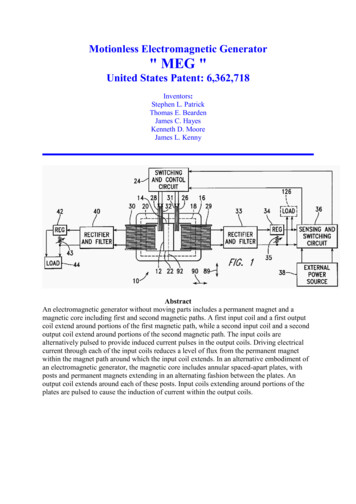
EM SCA Measurement & Correlation EM Attack (CEMA)- CLK: 15 𝑀𝐻𝑧- Correlation EM Attack window size 100 𝑛𝑠windowSCAEMEMwindowSCAns lation EM waveforms at the last encryption cycleVoltage(V)Voltage(V)EM waveformsCorrecCorIncorreInco 10MTD .2)AEBaseline(a.3)(a.2) Baseline AES EM field(a.3) Baseline53
EM SCA Measurement & Correlation EM Attack (CEMA)- CLK: 15 𝑀𝐻𝑧- Correlation EM Attack window size 100 𝑛𝑠windowSCAEMEMwindowSCAns lation EM waveforms at the last encryption cycleVoltage(V)Voltage(V)EM waveformsCorrecCorIncorreInco 10MTD .2)AEBaseline(a.3)(a.2) Baseline AES EM field(a.3) Baseline GI-AES secret key not revealed evenCLK15MHzCLK15MHzwithin 2 million traces,improvingresilience by TD 10000MTD 910000correlationcorrelationsize:100100ns nssize:CEMA results: Baseline & GI AEScorrelationcorrelationVoltage(V)Voltage(V) Baseline AES: Key Byte 1 is revealedEMEMSCAwindowwith 9000 AESfield 4) GI AESSCA54
Outline Side Channel Analysis (SCA) Prior Work: Power SCA resilient approaches Motivation: Susceptibility to the ground bounce Proposed Work- Principle of Galvanic Isolation (GI)- Proposed GI-AES architecture Test-chip measurement- Die photo, Measurement summary- Power SCA- EM SCA Comparison & Conclusion55
ComparisonISSCC’17[3]Technology130nmAES Power (mW)10.5AES Frequency40MHz1Area 75ISSCC'20[5]65nm1.250MHz0.205VLSI'20 [6]14nm8% 100MHz10% DigitalCurrentDigital LDO,LDOAttenuation ArithmeticRegulatorThis WorkBaselineProposed -1.425XImprovedGalvanic Vcc, Vss, tegratedVoltageRegulatorCPA MTD(1 Byte) 100,0008.4M1B1B5,000 3M 600X Time DomainMax t-value 2.511.95.2(1M 00 2M 220X FrequencyDomain4Max t-value EM SCA MTD6M(1 Byte)1Area overheads only2Area includes level shifters, PMU and capacitor switches56
Conclusion VSS ground bounce can reveal the secret keys if tapped by the attacker. Proposed galvanic isolation technique for VCC, VSS and substrate isolation improvesboth power and EM resilience. Measured results from a 128-bit AES core show- 600X improvement against correlation power attack (CPA)- 220X improvement against coarse-grained EM SCA attack- 20% lower frequency,- 2.3X more power- 0.0136 𝑚𝑚2 larger area.57
AcknowledgementsThis research is supported in parts by Intel, SiliconLabs, and NSF. Authors would like to thank TSMC forchip fabrication, Dr. Sanu Mathew, Dr. Raghavan Kumar,and Dr. Vivek De for helpful technical discussions.58
59
What will happen if you use the AES within a SoC, will be possible to isolate the fullSoC?It’s not applicable to isolate the full SoC. Because capacitor based GlavanicIsolation design will require a huge capacitor bank to supply the full SoC, which isnot area nor power efficient.Isolating the AES core alone is sufficient to increase its resilience and because ofthe dual rial sense amp as level shifters, the AES core can exchange data with theSoC with no concerns.60
ComparisonISSCC’09[1]Technology130nmAES Power (mW)33.32AES Frequency100MHzArea 75Countermeasure SC CurrentTypeEqualizerDuplicatedData al LDO,LDOAttenuation Hz0.205VLSI'20 [6]14nm8% 100MHz10% This WorkBaselineProposed -1.425XImprovedGalvanic Vcc, Vss, andIsolationsubstrateisolationCPA MTD(1 Byte)10M1M 100,0008.4M1B1B5,000 3M 600X Time DomainMax t-value --2.511.95.2(1M 0,000-6M1B1B9,000 2M 220X FrequencyDomainMax t-value EM SCA MTD(1 Byte)1Area overheads only2Area includes level shifters, PMU and capacitor switches61
Comparison table reference[1] C. Tokunaga, et al., ISSCC, 2009[2] M. Doulcier-Verdier, et al., ISSCC, 2011[3] M. Kar, et al., ISSCC, 2017[4] A. Singh, et al., ISSCC, 2019[5] D. Das, et al., ISSCC, 2020[6] R. Kumar, et al., VLSI, 202062
Prior Work: Power SCA resilient approaches referenceC. Tokunaga, and D. Blaauw “Securing Encryption Systems with a SwitchedCapacitor Current Equalizer” IEEE Journal of Solid State Circuits (JSSC), pp.23-31, Vol. 45, No. 1, January 2010A. Singh, M. Kar, J. Ko, and S. Mukhopadhyay, “Exploring power attackprotection of resource constrained encryption engines using integrated lowdrop-out regulators,” in International Symposium on Low Power ElectronicsDesign, 2015, pp. 134–139.M. Kar, A. Singh, S. Mathew, A. Rajan, V. De, S. Mukhopadhyay, “ImprovedPower-Side-Channel-Attack Resi
Power management unit Secondary side: crypto core power domain Proposed GI AES 22 Galvanic Isolation Crypto Logic Compute Domain External Power Domain L 1 L 2 GND 1 GND 2 V TOP VSS V BOT VCC Capacitor Bank 128 bit AES Core Scan Chain Interface Power