Transcription
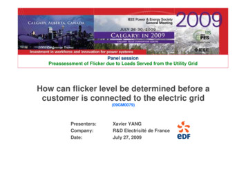
Panel sessionPreassessment of Flicker due to Loads Served from the Utility GridHow can flicker level be determined before acustomer is connected to the electric grid(09GM0079)Presenters:Company:Date:Xavier YANGR&D Electricité de FranceJuly 27, 2009
IntroductionLight flicker is visual discomfort caused by voltage fluctuationMainflickersources:Electric Arc FurnaceWelding machinesOther appliancesFlicker is defined as a power quality value by standards and grid access contracts. Flicker is one of themain complaints of LV customersGenerally, it is easy to measure overall flicker level at a point of grid, but it is not very easy to quantifyflicker emission level from one customer, particularly, when a number of customers have beenconnected to the grid.Flicker assessment is one of main tasks of a system operator before the customer connectionThis presentation will introduce flicker preassessment methods of IEC procedure and Frenchgrid access contracts2Xavier Yang (xavier.yang@edf.fr), July 27, 2009, IEEE PES GM in Calgary
Some IEC Standards regarding flicker issuesIEC procedure provides guidance on principles that can be used as the basis for determining therequirements for the connection of fluctuating installations to public power systems. Here are somerelevant standards: IEC 61000-2-2: the compatibility levels of flicker in public low voltage power supply systems IEC 61000-3-3, 61000-3-11, 61000-3-5 give flicker emission levels for LV equipment IEC technical report 61000-3-7: assessment of emission limits for the connection of fluctuatinginstallations to MV, HV and EHV power systems IEC 61000-4-15: technical specification of flickermeterPQ ContractsIEC 61000-3-3 ( 16A)IEC 61000-3-11 ( 75A)IEC 61000-3-5 TS ( 75A)IEC 61000-3-7 TRIEC 61000-4-15IEC Standards are not mandatory!3Xavier Yang (xavier.yang@edf.fr), July 27, 2009, IEEE PES GM in Calgary
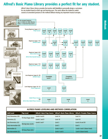
For information: IEC61000-4-15 FlickermeterIEC61000-4-15 defines a measurement chain: Voltage fluctuation - light flicker - visual discomfort:Figure by Alex McEachern, EPRI Power Quality Applications (PQA) and ADA 2009 ConferenceIEC61000-4-154Xavier Yang (xavier.yang@edf.fr), July 27, 2009, IEEE PES GM in Calgary
Flicker monitoring by IEC61000-4-15 flickermeterVoltage variationsThe IEC FlickermeterPCCIEC 61000-4-15 Flicker meterPst xPlt yFlicker phenomenonIEC/TR 61000-3-7:Flicker assessment,general flicker summation law5IEC 61000-4-15 flickermeter converts voltagechanges (magnitude and frequency) into unifiedflicker levels:short term flicker severity Pstlong term flicker severity Plt.Xavier Yang (xavier.yang@edf.fr), July 27, 2009, IEEE PES GM in Calgary
Review of flicker limits by IEC documents and Frenchgrid access contractDifferent flicker values in Pst and Plt :Load flicker emission limit (Pst 0.35, Plt 0.25) is the threshold below whichdetail flicker assessment study is not necessary. This limit is surely conservativeif the load is the only one flicker source at PCC.For the cases Pst 0.35 or Plt 0.25, different stages should be performed before acustomer is connected to the electric grid.6Xavier Yang (xavier.yang@edf.fr), July 27, 2009, IEEE PES GM in Calgary
French grid access contracts: flicker commitmentsIn France, both of TSO and DSO have their own grid access contracts with flicker commitments, rapidvoltage change limits and specifications of load connection procedures.CART (TSO grid access contract):Customer flicker contribution at PCC should guarantee TSO to comply Plt 1 as voltage characteristicsCARD (DSO grid access contract):Customer basic load flicker emission limits are Pst 0.35 and Plt 0.25.If these limits are exceeded, detail studies are necessary.Contract CARD (DSO)Contract CART (TSO)7Xavier Yang (xavier.yang@edf.fr), July 27, 2009, IEEE PES GM in Calgary
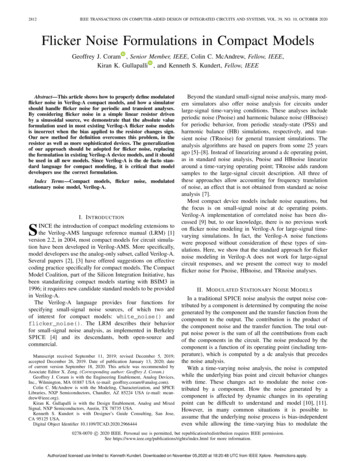
IEC method: simplified assessment by Pst 1 curveActual application of IEC flicker curve Pst 1 in pre-connection assessmentHere is an actual example.A manufacturer wishes to install a 50Hz electricwelding machine. The cycle repetition time of thewelder T (ON OFF) can be regulated from 2s to 20swith instantaneous powers P 400kW, Q 300kVArwhen welder is ON.As input technical parameters, total upstream gridimpedance at POE (MV of 20 kV, 50Hz) is given: Zg 3.59 j11.97 Ω.First, maxi relative voltage change at PCC caused bythe welder is calculated by powers P, Q and gridimpedance Zg:IEC61000-4-15 Pst 1 curve110 V Lamp230 V Lamp U R P X Q 3.59 400000 11.97 300000 1.26%UU220000 2From the curve, for Pst 1, voltage changes 10/min or T 12s (if the welder is the only one flicker source)8Xavier Yang (xavier.yang@edf.fr), July 27, 2009, IEEE PES GM in Calgary
IEC procedure Stage 1: Simplified flicker level evaluationIEC procedure Stage 1: by apparent power variation S and number of voltage changes rSsc S, rRecommendations by IEC61000-3-7Application of this method is very easy if S and r are known9Xavier Yang (xavier.yang@edf.fr), July 27, 2009, IEEE PES GM in Calgary
IEC procedure Stage 2: Emission limits relative toabsorption capacity of actual systemSystem operator can accept the connection of a load whose individual flicker emission limitexceeds the values defined by stage 1, if the actual grid has some more absorption capacity.PstplMV 0.9FlickerpropagationPstplH 0.8PstML 0.5TPUM0.8Psti 0.6(for stage 1: Pst 0.35)Based on planning level PstplMV at this PCC, the highest emission limit Psti high of the newinstallation should be defined by IEC summation law:Psti high 3 Pst plMV 3 (Pst plHV TPUM ) 3 Pst 310 0.69Xavier Yang (xavier.yang@edf.fr), July 27, 2009, IEEE PES GM in Calgary
IEC procedure Stage 3: the possibility of acceptanceof higher emission levels on a conditional basisIEC Stage 3 concerns the possibility of acceptance of higher emission levels on a conditionalbasis, i.e. all exception cases where the connection conditions can’t be met by studiesperformed in stage 2.Details studies are carried out to analyze the whole system capacity in flicker absorption inorder to decide whether the system operator can accept the higher emission levels on aconditional basis.A possible agreement should be discussed between system operator and customer.In France, a certain industrial site with electric arc furnace has get grid connection during a negotiatedperiod (Pst 1) in order that the customer can take necessary mitigation solution.If neither acceptance nor agreement could be made in this stage, the connection is impossibleand the customer has to take necessary mitigation solutions.Pst 1Solution?11Xavier Yang (xavier.yang@edf.fr), July 27, 2009, IEEE PES GM in Calgary
Flicker assessment study by simulation with IECflickermeter emulatorAs last resource for assessing flicker emission level from the irregular load variation cases, the methodbased on dynamic modeling is used by power quality engineer. The modeling can be carried out in a timedomain analysis or electro-mechanic transient simulation software, it includes:Grid modeling, Flicker source (dynamic load) modeling and IEC flickermeter emulation.Equivalent upstream gridRgU0LgDynamic loadmodelPOEFlicker meteremulator :PstIEC 61000-4-15flickermeter Waveform RMS values12RcUcXc ON/OFF loadMotor startingWelderEAF, et alXavier Yang (xavier.yang@edf.fr), July 27, 2009, IEEE PES GM in Calgary
Flicker assessment study by simulation with IECflickermeter emulator: some flicker source modelsPower evolution data offeredby manufacturersBy site recording in a similarinstallation13Xavier Yang (xavier.yang@edf.fr), July 27, 2009, IEEE PES GM in Calgary
Case study 1: Flicker assessment study by simulationwith IEC flickermeter emulatorHere is an example: An MV customer wants to install a 45kW LV electric motor in a production process, themotor will be powered by a 1 Mva transformer behind the PCC. The motor will be used with direct linestarter every 10s; the starting duration is 1s with peak starting current of 6.2xIn and the motor runs during5 s at each working cycle. Here is the electromechanical transient simulation result at PCC:Q in kvarP in kWRemark:In an electromechanicaltransient simulation, theflickermeter emulator mustaccept RMS voltage at inputvalues (modified version ofIEC61000-4-15).Necessary modification isnecessary [14].The simulation shows the Pst at PCC is 0.345. So it is compliant with stage 1 assessment14Xavier Yang (xavier.yang@edf.fr), July 27, 2009, IEEE PES GM in Calgary
Case study 2: Flicker assessment study by simulationwith IEC flickermeter emulatorAnother example of flicker assessment at POE concerns an electric arc furnace (EAF, 70MW, 50Hz)connected at HV grid.Ssc 3000 MVAStage 1: simplified computationFor an arc furnace, we can take total rated power as fluctuating one, so the power ratio S/Ssc atPOE reaches 2.33%. Stage 1 criteria of IEC61000-3-7 does not be applied due to the high ratio ofthe fluctuating power to short-circuit power for r 200/min (see Table II).In this case, stage could be complied only if S/Ssc at POE 0.1%.15Xavier Yang (xavier.yang@edf.fr), July 27, 2009, IEEE PES GM in Calgary
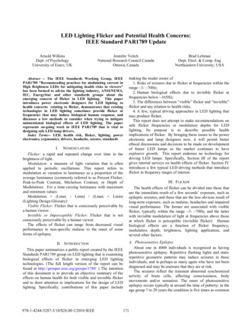
Case study 2 (followed): Flicker assessment study bysimulation with IEC flickermeter emulatorThis case has been studied by the simulation of grid, flickermeter and dynamic load in a PQ softwarebased on electromechanical transient computation:Dynamic EAFmodelingVoltage in kVP(MW)Q(MVAr)Flicker meteremulatorThe simulation shows only the EAF can cause Pst 2.184 and the compatibility level is exceeded.A stage 2 study at this POE is not necessary and the customer shall discuss with system operator if astage 3 study is possible. If a direct connection of this load is impossible from stage 3 study, the customershall take additional corrective measures to reduce the flicker emission level.16Xavier Yang (xavier.yang@edf.fr), July 27, 2009, IEEE PES GM in Calgary
Conclusion IEC flicker assessment procedures have been used and adapted by systemoperators into their grid access contracts. It is possible to apply some simplifiedIEC methods to accomplish pre-connection studies with compliance of relevantIEC standards and local power quality commitments. For sophisticate case studies, the recommended method is to perform gridsimulation with IEC flicker meter emulators and flicker load models. The grid canbe modeled by an equivalent fictitious model or directly by accessing systemoperator’s database. A flicker meter emulator is recommended in power qualitysoftware. Flicker meter method can make acceptable flicker assessment of anyfluctuating installations to connect to the grid. French grid system operators have integrated IEC flicker assessment rules intheirs grid access contracts and studying tools (Simple flicker calculator, on-linetool for system operators, simulation software for power quality engineers).17Xavier Yang (xavier.yang@edf.fr), July 27, 2009, IEEE PES GM in Calgary
installation should be defined by IEC summation law: 0.69 Pst plH 0.8 TPUM Psti 0.6 Pst ML 0.5 Pst plMV 0.9 0.8 Flicker . domain analysis or electro-mechanic transient simulation software, it includes: Grid modeling, Flicker source (dynamic load) modeling and IEC flickermeter emulation. ON/OFF load Motor starting Welder