Transcription
Electromagnetic SimulationTechniques for Connectorsand PCBsBill McGinnAnsys Sr. Application Engineer
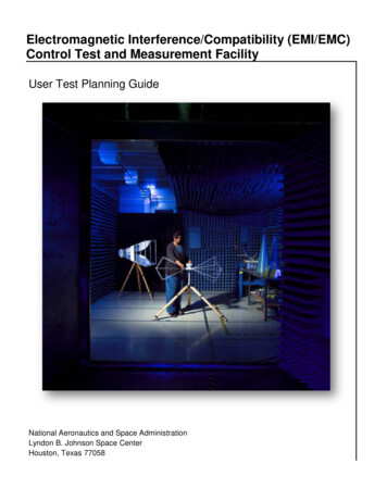
ANSYS is the Simulation LeaderTRUSTEDFOCUSED96This is all we do.Leading product technologies in all physics areasLargest development team focused on simulationCAPABLEof the top 100FORTUNE 500 IndustrialsISO 9001 and NQA-1 certifiedPROVEN3,700 employeesRecognized as one of the world’s MOST INNOVATIVEAND FASTEST-GROWING COMPANIES*75INDEPENDENTlocationsLong-term financial stabilityCAD agnostic40countriesLARGEST3xThe size of ournearest competitor*BusinessWeek, FORTUNE
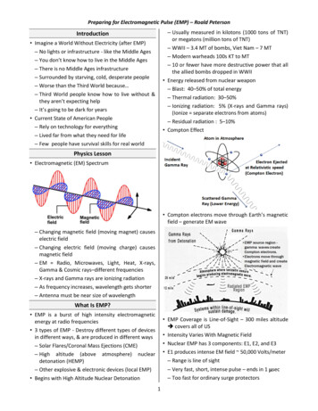
Breadth of TechnologiesFluid Mechanics:From Single-Phase FlowsTo MultiphaseCombustionStructural Mechanics:From Linear StaticsTo High-Speed ImpactElectromagnetics: FromLow-Frequency WindingsTo High-FrequencyField AnalysisSystems:From Data SharingTo Multi-DomainSystem Analysis
Summary Brief Overview of EM Techniques FEM and TransientConnector on Board “Assembly” SimulationHFSS 3D ComponentsThermal Simulation of EM ModelsEMI Analysis using HFSSEMI Scanner
AEDT: ANSYS Electronics DesktopSingle Desktop for: HFSSHFSS 3D LayoutCircuitThermal Tight integrationbetween circuit and3D EM simulation
HFSS: High Frequency Structure Simulator Full-wave FEM 3D electromagnetic fieldsolver‐ Computes electromagnetic behavior of highfrequency and high-speed components andsystems‐ Extracts S-, Y-, and Z-parameters‐ Provides 3D electromagnetic fields ation: Antennas, EMI/EMCSignal Integrity/High Speed Digital Packages PCB Connectors Transitions
HFSS Transient Now Included with HFSS Time Domain Finite element solver Faster implicit solver (New 2019)Improved Auto-HPC performance (New 2019)Unstructured FEM Mesh based on Tets (variable size, variable order, conformal)Adaptive meshingLocal time steppingWaveform input flexibility (oblique angles)
HFSS 3D Layout
HFSS: Arbitrary 3D Geometry EditorMechanical CAD (MCAD)
HFSS 3D Layout DesktopMenu barTool barLayout EditorNets WindowProject ManagerLayersWindowProperty WindowComponents WindowMessage ManagerProgress Window
StackupStackup Editor : Manufacturing TolerancesImage courtesy of AMKOR
Stackup Editor : Surface Roughness Surface Roughness‐ Huray or Groisse Roughness Models Per Layer based Per polygon basedSurface roughnessStackup
HFSS 3D Layout: “Connector-on-Board”Combine ECAD (PCB, Package) and MCAD (Connector) in single design and simulation flowSingle 3D Mesh
System Analysis within HFSS 3D LayoutAssemble ECAD & MCAD Select appropriate solver HFSS or SIwave Connect TX/RX up withinSchematic LNA IBIS & IBIS-AMI QuickEye, VerifEye HSPICE* PSPICE***Requires Synopsys license;Nexxim supports HSPICE syntax** Uses Nexxim solver withPSPICE syntax
3D Layout Capabilities and Performance MCAD Utilizes “TAU” Mesher ECAD Utilizes “PHI” Mesher New ECAD MCAD mesh assembly processPhi is used when appropriateMaterial overrides supportedParallel ECAD meshing Faster mesh generation Numerical de-embedding of non-rectangularlumped ports
New: Full Assembly - ECAD MCAD Mesh AssemblyMCAD3D Layout3D Layout: Full AssemblyGeometry changes canquickly be implemented,adaptive meshing givesconfidence on everysolution without userinteractionHFSSSimulation2D Crosssection ofmeshAutomatically generatedmesh shown on PCB Automated Mesh Creation Accurate Efficient Solve time independent of port count Capture full network parameters for all netssimultaneously with low computational overhead Captures small and large features efficiently Small pitch traces, meandering traces, accuratecoupling and isolation
Simulation Setup Example: Multi-die Laminate Assembly and meshing technology significantly speeds up simulationsetup time 12 Filters, two SMD (as HFSS 3D Components), one Laminate1. Component Creation via Scripted Automation – 7x faster 3D: 21mLayout w Mesh Assembly: 3m (Laminate/BAW SMD)Representative design only2. Assembly Creation – 5x faster 3D: 9m Validation ( 13m)Layout w Mesh Assembly: 2m Validation ( 2m) 2019 R1 Flow Improvements3. Project Opening – 5x faster HFSS Layout 3D with Mesh Assembly 3D: 4m Layout w Mesh Assembly: 45s4. Initial Mesh – 1.6x ( 850k tets)1. 3D: 1h9m2. Layout w Mesh Assembly: 44m5. Adaptive Mesh – 1.2x1. 3D: 186m (144GB RAM)2. Layout w Mesh Assembly: 156m Non-graphical Script Execution (Beta) Reduction in 3D Component size-on-disk Reduced 3D Validation Time Faster initial mesh time Faster user experience
Electromagnetics HighlightsIntegrated Transient Circuit SimulationAssemble electronic system then perform electromagnetics plus transient circuit analysis system automatically
HFSS 3D Layout Improvements Far Field Post-Processing Enhancements Consistent with HFSS 3D PML Support Enhancements for on-chip inductor modeling Dielectric Stackup Simplification Via clustering
HFSS 3D Layout Port Configuration Enhancements Wave port support for mesh assembly i.e. “connector-on-board” Usability improvements Visualize wave port de-embed distance Layer control for Pin-groups and internal/ref ports Separate de-embedding/distance settings
Stackup Wizard in 3D Layout Design Quick selection of number/type of layers Single-ended & Differential trace synthesis & analysis Etch factor considered in trace computations Convenient 3D viewer
High Frequency Signal Integrity Single environment allows extraction of component models such as vias, connectors, and transmission lines as well as concatenatingthese and other models into a channel schematic S-parameters, eye diagrams, and bit error rate of channel can be simulated Individual components can be optimized and channel results updated quicklyTXRX
3D Components
3D Components 3D Components‐ Save and reuse designs‐ Share with partners,vendors andcolleagues Contains‐ Geometries‐ Material properties‐ Boundary conditions‐ Excitations‐ Encryption
3D Components: Library Browser Easy availability of 3D Components Drag and drop of component geometry into modeler window
3D Component: Edit Definition3D Component Edit An existing component can be flattened to a new design
TDK Chip Antenna 3D Component Library Library of TDK RF chip antenna 3D Components with encryption
ANSYS HFSS 3D Components 3D Component Licensing Vendors can create and license 3D components Vendors can control distribution and lifespan ofcomponent usage Secure licensing using digital signature Fits into standard component creation and useworkflow 3D Component Logo and Properties Dialog Support Vendor URL For example these links could be used to directcomponent user to help or vendor library website
Creating a 3D Component To create component selectobjects from modeler windowand go to– “Create 3D Component ” Enter Design information Select parameters to include– Objects– Boundary conditions andexcitations– Design parameters Review image Save to system, user orpersonal library folders– Update menu
Inserting a component Insert 3D Component– Review Parameters Component in modeland project trees Component design datain project tree Component parametersin the property box Treat as custom defined3D primitive
3D Component Assembly Meshing Per-component model settingsPer-component meshMesh in parallelECAD MCAD mesh assembly processComponent based unitsOvercomes aspect ratio issuesMultiple instances for same componentMesh re-use for parametric analysis
AEDT Thermal Analysis
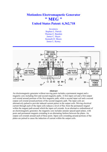
ANSYS Icepak – Computation Fluid Dynamics SolverIcepak is an integrated “Electronics Cooling” solution for connectors, packages,printed circuit boards and electronic systems‐‐‐‐‐‐‐Fluid flowConjugate heat transferSteady-State ThermalMulti-physics couplingSingle or multiple fluidsParametricsOptimizationTemperature contours and fluid velocity vectors of a fancooled rack mounted computerVelocity streamlines and temperature contours for acard array in a VME box cooled by three axial fans
Icepak – ANSYS Electronics Desktop Integration Supported Workflows MCAD SupportECAD PCB workflowEM loss coupling with HFSS, Maxwell and Q3DEfficient Electronics Cooling CFD solution Setup - Meshing - Solution (HPC) Optimetrics and integrated post-processingSupported Thermal Physics Steady-state flow and thermal Conjugate heat transfer, including radiation Laminar and turbulent flow modeling Modeling Comprehensive thermal and flow boundaryconditions Native 3D Components : Fans (2D & 3D), Heatsinks,PCBs Libraries Complete solid, fluid and surface materials library Vendor component libraries: Fans, Heatsinks, BGAComponents
Material Library for Electrical, Thermal, & MechanicalMaterials for Thermal Physics Surface materials : Paint, metals, plastics etc. Solid materials : Insulations, epoxy, metals, Heat-spreaders, package materials, etc. Fluid materials : Liquid, gaseous materials relevant to electronics cooling applications
AEDT Icepak 3D Components LibrarySupport-Variable Fan libraryVariable Heatsink libraryCustomized ComponentNative 3D Components for Creating Fans,Heatsinks and PCBsComponent Library of Parts- Fans : Adda, Delta, EBM, Elina, Jaro, Nidec, NMB, Panasonic, Papst, SanyoDenki, Sunon- Heatsinks : Aavid
Integrated with ANSYS Electronics Desktop Leverage Electronics Desktop HPC Platform– Easy to use– Includes Linux scheduler integration Progress and Profile Reporting– Meshing and solution process– Enhanced profile reporting– EM loss assignment
Icepak: Two-Way Coupling with HFSS, Maxwell, Q3D New Coupled Simulation Controller in Icepak Design User specified “Number of Coupling Iterations” Options to “continue” Icepak iterations during coupling Single controller per design Updates to EM losses in each coupling iteration Multiple EM Losses supported Icepak-Optimetrics Integration
2-Way Electro-Thermal Coupling Valid for HFSS, Q3D, and Maxwell design types Utilizes thermal modifier for materials and temperature feedback in electromagnetic design New 2-way Coupling controller in Icepak design Allows for additionalIcepak iterations betweenmaterial updatesHFSS Design of a High Power Waveguide Load40Maxwell Design of Planar Transformer
AEDT Icepak – Post-ProcessingThermal conductivity XTopBottomHFSS 3D layout FieldTemperatureVelocityTemp w/param AirflowThermal plot & PCB mesh
HighlightsNEW 2-way thermal coupling to HFSS, Q3D, and Maxwell design typesNEW 1-way thermal coupling to SIwave DC IR solver in AEDTNEW Import .tzr archive from Classic Icepak interfaceNEW 2D & 3D profile boundary conditions using datasets Workflow Improvements‐ Solution setup streamlined‐ Rotated PCB components‐ MCAD fan objects can be simplified into Icepak primitives Mesher Improvements‐‐‐‐General mesh speed and quality improvementsAllow for simplified stair-step meshingControl over uniform mesh sizingAdded the capability to enforce 2D cut cell meshing in a specified coordinate direction Classic Icepak Enhancements‐‐‐‐Job submission to supported schedulers – within and across Windows/Linux platformsAbility to export unencrypted ECXML filesMonte Carlo radiation model added (BETA)Per Object meshing controls & Mesh re-use (BETA)
EMI EMC
EMI Capabilities Resonant Mode Power and ground plane resonant mode solver. Induced Voltage (Susceptibility) Models a plane wave incident to the PCB. Monitors voltages induced at port locations. Near-Field Computes the near-field E- and H- fields close to the board. Far-Field Computes the far-field radiation.44
Induced Voltage (Susceptibility) Models a plane wave incident to the PCB Monitors traces and planes for excitation
Induced Voltage – 10GHz Plane Wave ExcitationAnimation
Near-Field Computes the near-field E- and H-field at a specified distance from themodel Mimics near-field probing that is commonly done with a spectrum analyzerto pinpoint localized sources of EMI
Near-Field E-Field Pattern
Far-Field Computes the radiation pattern and strength of the E-field in the far-field Mimics Radiated Emissions testing used for EMC Compliance Can be calculated for 3m, 5m, 10m testing
Far-Field Radiation Pattern
Microstrip w/ Slot – Varying Gap WidthTransmission Line models that assume perfect reference planes do not show the impact of non-ideal return pathsCM or DM radiation is proportional to the areas of the loops (s or h),which are set by the PCB/Connector technology and designstrategies.Animation
Near-Field E-Field – 2.1 GHzHFSSFloating ReferenceHFSSSIWave
Microstrip w/ Slot - HFSS – Vector E-Field at 3mm above Slot6.2 GHzAnimation
ANSYS EMI Scanner Either HFSS or SIwave can utilize the EMI Scanner No additional license needed EMI Scanner runs directly in either tool54
Electromagnetic Interference RulesWiring/ CrosstalkSignal Reference Net Crossing Split Net Changing Reference Net Near Edge of ReferenceExample: Net Near Edge of ReferenceExample: Net Crossing SplitPlane TraceEdge Critical Net Near I/O NetExposed Critical Trace LengthCritical Net IsolationCritical Differential Net MatchingWide Power/Ground TracesExample: Via Stub LengthDecoupling Decoupling Capacitor DensityPower Pin to Capacitor DistanceIC Power/Ground Pin to Via DistanceDecoupling Cap Distance to ViaPower/Ground Trace DecouplingPower Via DensityExample: IC Power Pin to Via DistanceWade to create apictureExample: Decoupling Capacitor Distance to ViaExample: Net to Net Coupling
Summary Brief Overview of EM Techniques FEM and TransientConnector on Board “Assembly” SimulationHFSS 3D ComponentsThermal Simulation of EM ModelsEMI Analysis using HFSSEMI Scanner
24.04.2019 · ANSYS Icepak –Computation Fluid Dynamics Solver Icepak is an integrated “Electronics ooling” solution for connectors, packages, printed circuit boards and electronic systems ‐Fluid flow ‐Conjugate heat transfer ‐Steady-State Thermal ‐Multi-physics coupling ‐Single or multiple fluids ‐Parametrics ‐Optimization Velocity streamlines and temperature contours for a card array in .