Transcription
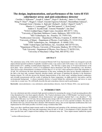
The design, implementation, and performance of the Astro-H SXScalorimeter array and anti-coincidence detectorCaroline A. Kilbourne*a, Joseph S. Adamsa,b, Regis P. Brekoskyc, James A. Chervenaka,Meng P. Chiaoa,b, Megan E. Eckarta, Enectali Figueroa-Felicianod, Masimilliano Galeazzie,Christoph Greinf, Christine A. Jhabvalaa, Richard L. Kelleya, Daniel P. Kellya,g,Maurice A. Leuteneggera,b, Dan McCammonh, F. Scott Portera,Andrew E. Szymkowiaki, Tomomi Watanabea,j, Jun ZhaofaNASA Goddard Space Flight Center, Greenbelt, MD 20771 USA,bUniversity of Maryland, Baltimore County, Baltimore, MD 21250 USA,cMEI Technologies, Inc., Houston, TX 77058 USA,dNorthwestern University – Department of Physics, Evanston, IL 60208 USA,eUniversity of Miami – Department of Physics, Coral Gables, FL 33124 USA,fEPIR Technologies, Inc., Bolingbrook , IL 60440, USA,gASRC Federal Space and Defense, Inc., Greenbelt, MD 20770 USA,hDepartment of Physics, University of Wisconsin, Madison, WI 53706 USA,iYale University– Department of Physics, New Haven, CT 06520 USA,jUniversity of Maryland, College Park, MD 20742, USAABSTRACTThe calorimeter array of the JAXA Astro-H (renamed Hitomi) Soft X-ray Spectrometer (SXS) was designed to provideunprecedented spectral resolution of spatially extended cosmic x-ray sources and of all cosmic x-ray sources in the Fe-Kband around 6 keV, enabling essential plasma diagnostics. The SXS has a square array of 36 microcalorimeters at thefocal plane. These calorimeters consist of ion-implanted silicon thermistors and HgTe thermalizing x-ray absorbers.These devices have demonstrated a resolution of better than 4.5 eV at 6 keV when operated at a heat-sink temperature of50 mK. We will discuss the basic physical parameters of this array, including the array layout, thermal conductance ofthe link to the heat sink, resistance function, absorber details, and means of attaching the absorber to the thermistorbearing element. We will also present the thermal characterization of the whole array, including thermal conductanceand crosstalk measurements and the results of pulsing the frame temperature via alpha particles, heat pulses, and theenvironmental background. A silicon ionization detector is located behind the calorimeter array and serves to rejectevents due to cosmic rays. We will briefly describe this anti-coincidence detector and its performance.Keywords: microcalorimeter, x-ray calorimeter, anticoincidence detector, Astro-H, Hitomi, SXS, x-ray spectroscopy1. INTRODUCTIONAn x-ray calorimeter provides extremely high spectral resolution by measuring the energy of each incoming photon afterit has thermalized in a low-heat capacity absorber. The 36-pixel calorimeter array of XRS/Suzaku1 was based on micromachined, deep-diffused, ion-implanted silicon thermometers2 and separately attached HgTe x-ray absorbers,3,4. Thepitch of the XRS array was 0.64 mm, but an alternate array design with 0.83-mm pitch was successfully fabricated andconsidered for flight as an option for increasing the field of view at the cost of worse spectral resolution. The array forthe Hitomi SXS was selected from these alternate XRS thermistor arrays, but several important modifications that wereimplemented for SXS made possible even better energy resolution than XRS.There were three significant improvements made to the fabrication and operation of the calorimeter array between XRSand SXS: 1) The change of the heat-sink temperature from 60 mK to 50 mK, 2) development of HgTe absorbers withlower specific heat, and 3) improved heat sinking of the calorimeter array die. These improvements enabled the typical*caroline.a.kilbourne@nasa.gov
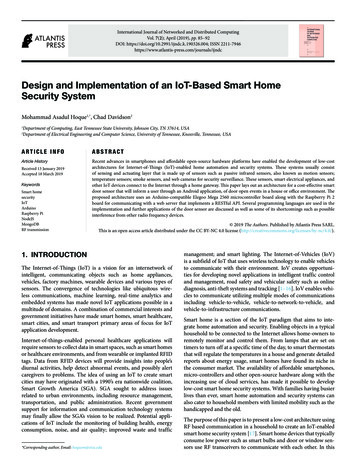
resolution at 6 keV to improve from 5.5 eV full-width at half maximum (FWHM) to 4 eV FWHM, despite the 70%larger absorber area. Early results from use of the improved absorbers were presented elsewhere5,6, but here we presentmore detail on this and the other improvements.The anti-coincidence (anti-co) detector is a Si ionization detector designed to operate at 50 mK. The SXS anti-co was aspare component from XRS, mounted to a different fan-out board, which was modified for reasons unrelated to anti-coperformance.2. X-RAY CALORIMETER PIXELSHigh-resolution x-ray calorimeters require absorbers with low heat capacity, to allow a large increase in temperature fora given deposition of energy, yet good x-ray stopping power. Additionally, the material must thermalize quickly andreproducibly, so that the same deposition of energy always results in the same temperature increase, independent ofwhere the energy is absorbed. The choice of the semi-metal HgTe is a compromise between these competingrequirements. Many materials have lower specific heat than HgTe, but do not thermalize well.The heat capacity of the HgTe used in the XRS calorimeter array had both a large lattice term, from its relatively lowDebye temperature of 145 K7,8, and an electronic term. The lattice term varies as T3 and the electronic term varies as T,where T is the absolute temperature. For the XRS absorbers, the electronic term was equal to the lattice term at 0.1 K,and was roughly a factor of two higher than the lattice at the electrically biased operating point of 74 mK. Nagata, et al.7showed that the electronic term could be reduced by annealing HgTe in a Hg atmosphere, demonstrating that this termcan be dominated by unintended doping of the material as a result of Hg vacancies. In early discussions between theteams at Goddard, EPIR Technologies, and Wisconsin, EPIR suggested that while HgTe could be produced with anegligible electronic specific heat, Hg0.834Cd0.166Te, the zero-bandgap composition of the HgTe/CdTe alloy, was morepromising for minimizing this term because of its much lower electron effective mass.6 Additionally, due to the higherDebye temperature of CdTe, HgCdTe also promised a slightly lower lattice specific heat.EPIR produced samples of HgTe and HgCdTe, both grown by molecular-beam-epitaxy (MBE) and annealed in a Hgvapor. Both were shown to have negligible electronic specific heat. Although the HgCdTe absorbers resulted in slightlylarger signals, there was no significant difference in the spread of resolutions obtained using the two materials. Thissimilarity was demonstrated for incident energies of 5.9 keV, 3.3 keV, and 1.5 keV. Because the performance exceededrequirements for both materials, with no distinction, we chose HgTe because it was the simpler material. Fig. 1 showsthe distribution of resolutions in test devices with both HgTe and Hg0.834Cd0.166Te absorbers. The pixels were in thesame array and thus had similar temperature sensitivity. The Hg0.834Cd0.166Te histogram is displaced vertically forclarity.For XRS, the HgTe material was mechanically diced to form the square absorbers, leading to possible damage at theboundaries. For SXS, EPIR delineated the absorbers via a dry etch. In addition, a serial number was etched into eachabsorber. This number was useful to identify absorbers in a package after visual screening. If there had been nonuniformity in the HgTe layers, good and bad regions could have been identified by number. As done for XRS, theabsorbers were attached to the SU-8 polymer stand-offs on each suspended thermistor with epoxy by hand. The processwas assisted by a micrometer controlled XYZ stage and a microscope. The right side of Fig. 1 shows one of the flightcandidate arrays for SXS after some of the absorbers had been placed. The pixel pitch is 0.832 mm. The identifyingnumbers on the absorbers are on the downward facing side because the dry etch left the sidewalls slightly beveled, andthe tight positioning tolerance required that the widest face be on top. The typical width of the top face was 0.819 mm.The SXS doped silicon thermometers are essentially thermistors. When an x-ray warms a pixel, the change in resistancecauses a change in the voltage drop across the sensors. We have constructed a detector model that includes theresistance as a function of temperature R(T), the absorber and thermistor heat capacities, the thermal conductances (ofthe links between the absorber and thermistor, between the thermistor electrons and phonons, and of the 1.5-micronthick Si beams between the thermistor and thicker silicon containing the array), the load resistor that is in series with thethermistor and the bias voltage applied, and assorted other terms such as stray capacitance, power loading from strayinfrared radiation, and circuit noise. The characterizations of the SXS detectors have not completely fixed the values ofall of these parameters. In particular, fits to current-voltage measurements have determined a lower value for thethermal conductance of the support beams than appears to best describe the pulse shapes and heights. Table 1 lists someof the key parameters for the XRS and SXS devices to compare them qualitatively, although some values may be refinedwith further work.
Ideally, the resistance in a doped semiconductor at low temperatures will be governed by the equation for variable rangehopping in the case of a Coulomb gap9: R(T) R0exp((T0/T)0.5), where R0 and T0 are constants, however, deviations atlow temperatures have been reported10, and various empirical expansions of the resistance function, with more or lessphysical justification, have been used to describe the behavior. In Table 1, rather than quote parameters of oneresistance function or another, we cite simply α, where α log(R)/ log(T).Figure 1. Left: Accumulated resolution statistics for tests of absorbers made of annealed HgTe and Hg0.834Cd0.166Te. Thedistributions were nearly identical despite the lower specific heat of the Hg0.834Cd0.166Te. The histogram of Hg0.834Cd0.166Teresults has been displaced upward for clarity. Right: Portion of a flight-candidate array after several absorbers have beenplaced. Three suspended thermistors without absorbers can be seen in the upper left of the photograph. The absorbers areglued to 0.01 mm tall SU-8 tubes on the four tabs around each thermistor. Also visible are the four silicon support beamsthat provide controlled thermal isolation between the thermistor and the heat sink. The pixel pitch is 0.832 mm and thetypical width of the front face of an absorber was 0.819 mm.Table 1. Comparison of representative pixel properties of the XRS and SXS arraysParameterSuzaku XRS valueHitomi SXS valueHeat-sink temperature60 mK50 mKOperating temperature under bias74 mK63 mKC of absorber at 0.1 K / operating point0.21 pJ/K /0.11 pJ/K0.24 pJ/KG to heat sink at 0.1 K / operating point160 pW/K /60 pW/K130 pW/K / 28 pW/KR at operating point27 MΩ34 MΩα log(R)/ log(T)-7.0-6.3Pulse fall time3.5 ms3.5 msTypical energy resolution, instrumentground testing5.7 eV4.2 eV/ 0.06 pJ/K
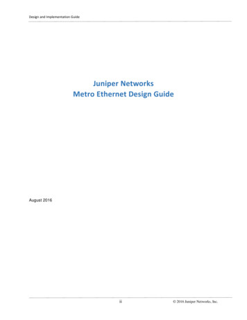
Figure 2. Top left and right: backside layer of Au, with view at left showing the extent of the coating onto the walls of theback-etch well behind each pixel. Bottom: finished SXS spare array, with heat sinking (and absorbers).3. THERMAL PROPERTIES OF THE ENTIRE ARRAY3.1 Additional heat-sinking gold and its limitationsThe Suzaku XRS array was thermally anchored via an epoxy bond to an alumina board connected to the heat sink viagold wire bonds. The weak coupling of this epoxy bond resulted in several non-ideal effects. Gain and resolutiondepended on the x-ray flux incident on the array. The resolution also depended on the cosmic-ray rate through particleinteraction with the frame, and large energy deposition ( 200 keV) into the frame produced a temperature pulse bigenough to cause signal pulses on many pixels simultaneously, wasting telemetry bandwidth. In order to minimize theseeffects on the Astro-H SXS array, a thick gold layer was added to the frame of the array to increase its heat capacity andto permit heat sinking via gold wire bonds. Specifically, electron-beam-evaporated gold (1.5 micron) was deposited in
areas on the front and back through shadow masks. In the case of the back-side deposition, the chips were angled toavoid deposition on the suspended thermistors. Gold wire bonds thermally connect the top-side gold to the gold of thealumina fan-out board. The montage of Fig. 2 shows the back and front Au layers and the Au ribbon bonds of the spareSXS array.To characterize arrays in both the XRS and SXS style, we attached additional heaters and thermometers to the frame andfan-out board of sample devices. The XRS arrays were bonded with epoxy to alumina boards, the thick gold coating ofwhich was connected to the heat sink via gold wire bonds (40 bonds, 3 mm long, 0.025 mm diameter). We typicallymeasured G 10-7 W/K from the array to the board, and 10-5 W/K from the board to the heat sink at 60 mK. Replicatingthe heat-sinking wirebond interface at the array thus initially appeared to have the potential to improve the heatsinkingby two orders of magnitude.There are other thermal interfaces that need to be considered, however. Each gold triangle on the front of the SXS arraycovers 8 mm2. If the electron-phonon coupling constant Σ 1.4 x10⁹ W/K5m3 (as we have measured in other devices),then for volume V, Gep 5VΣT4 5x10⁻⁷ W/K for 1.5 micron Au at 50 mK. Using the Au/Si boundary conductance ofSchwarz and Pohl11, the thermal conductance from the frame into each Au triangle is 6x10⁻⁷ W/K. For a residualresistivity ratio (RRR) 6, the thermal conductance across one of the Au triangles is also 10-6 W/K. If we assume a 1mm mean-free path for the underlying silicon (0.38 mm thick), then the conduction between the front-side and back-sidegold in each area of overlap 2x10⁻⁶ W/K. Combining these terms in series, and accounting for two heat-sinking regionsand the parallel conduction through the epoxy bond, it becomes clear that an increase in heat sinking by less than a factorof 10 should be expected. In fact, measurements of the heat sinking on arrays with large differences in the number,length, and cross-sectional area of the gold wire bonds repeatedly resulted in G 6-8 x 10⁻⁷ W/K, consistent with thevarious interface terms dominating G. While this presages the challenges of heat sinking large arrays in futureinstruments, the improvement over XRS is nonetheless substantial.The nominal heat capacity of the added Au at 50 mK is 8x10⁻¹⁰ J/K, thus we expected the cooling time constant for thewhole chip to be 1 ms.Summarizing the array-scale thermal conductances: Gold wire bonds: 10-5 W/K Electron-phonon in top film: 10-6 W/K Au/Si boundary: 10-6 W/K Au conduction: 2x10⁻⁶ W/K Top/bottom conduction in Si: 4x10⁻⁶ W/K Si/epoxy: 10-7 W/K (parallel)3.2 Thermal crosstalkAnother implication of inadequate heat sinking is thermal cross talk. Even XRS had no triggerable thermal cross talkfrom x-ray absorption on other pixels, but small crosstalk pulses contributed to a rate-dependent (and spectrumdependent) noise. On XRS, the nearest-neighbor crosstalk (as determined from record averaging) was a factor of threehigher than from other pixels, but beyond that immediate radius the crosstalk fraction flattened out, showing that thelimiting time constant was of the entire chip cooling.For the SXS array, we measured the thermal cross talk in the same way, using the 59.5 keV gamma-rays from 241Am toimpart a thermal impulse into the trigger channel, and averaging the simultaneous records on other pixels to look forcross talk. The crosstalk fraction was determined from comparison of the crosstalk pulses to the response of each pixelto 5.9 keV, scaling from the 59.5 keV input. The results of these measurements are shown in Fig. 3 and tabulated inTable 2. The thermal cross talk in SXS is not only less than observed in XRS, it continues to fall off with distance,merging with the noise in the furthest pixels (for 220 averaged records each). The SXS arrays benefit not only from thegold deposited on the back, but also from the thicker silicon between pixels that is a consequence of the larger pitch.Analysis of high-count-rate data indicates that the dependence of gain and resolution on flux is greatly diminished.
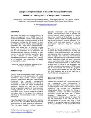
Figure 3. Left: Averaged thermal crosstalk pulses, overlaid with the response to a 6 keV x-ray. Right: Channel map – thegroup trigger was based on 59.5 keV gamma-ray events on Channel 0.Table 2. Thermal crosstalk intensity for SXS, compared with XRS. Channel numbers correspond to the numbering in thearray schematic of Fig. 3.channel number717361934322385353124relationshipnearest neighbor, exteriornearest neighbor, interiornearest neighbor, interiordiagonal neighborsecond nearest neighborsecond and diagonalsecond along diagonalsecond nearest neighbor, edgesecond along diagonal, edgethird nearest neighbor, edgethird and diagonal, edgefar cornerfraction of .1E-06 1E-5 1E-51.1E-05 1E-5 1E-5XRS 042.5E-042.5E-042.5E-042.5E-042.5E-042.5E-043.3 Thermal response to cosmic-ray interactions in the frame of the arrayIn ground testing of the Suzaku XRS array, we identified groupings of simultaneous signals resulting from cosmic raysdepositing energy in the silicon frame of the array12. The rise times of these pulses were similar to the rise times of x-rayevents, thus they could only be identified by coincidence screening. In orbit, the rate of these clustered events tracked theorbital variation in the rate of events in the anti-coincidence detector. Since a majority of the pixels triggered for each ofthese frame events, the XRS telemetry was full of them, and events too small to trigger degraded the energy resolution ofthe x-ray events.13, 1
Figure 4. Correlated background events on XRS (top and middle) and SXS (bottom). In all plots, the right-hand axis givesthe anti-coincidence rate (solid curve), which is plotted as an indicator of the cosmic-ray rate. Each point is the energy of acalorimeter event (left axis), shaded according to pixel number.
In ground testing of the SXS prototype arrays, there were so few clustered events that it was not possible to assesspositively whether they were the same phenomenon on a different scale, or due to some other environmentalinterference. Exposure of the frame of a test device to alpha particles from 241Am did not produce any triggers. Heaterpulses simulating energy impulses to the frame of 161 MeV and 446 MeV produced large slow events on multiple pixelsat a scale apparently consistent with the lack of triggers from 5 MeV alpha particles.In orbit, SXS data clearly showed correlated events as on XRS, but at a much lower rate. Fig. 4 illustrates the difference.The top two panels show 90 minutes of XRS background data, with the top covering 0 – 10 keV and the middle covering0 – 0.5 keV. The bottom panel shows 90 minutes of SXS data. In all panels, the right-hand axis gives the anticoincidence rate (solid curve), which is plotted as an indicator of the incident particle rate. Comparing XRS and SXSover the same energy range, the SXS data contain far fewer grouped events. Interestingly, the SXS distribution of eventsfrom 0 – 0.5 keV looks similar to the XRS distribution over the 0 – 10 keV band, as if the same input distribution wasresulting in events smaller in SXS by a factor of 20. The SXS frame events are generally more slowly rising and fallingthan the ones on XRS. There are smaller clustered events that have faster rise times, but preliminary inspection indicatesthat these have some ringing at the leading edge, confusing the rise-time calculation, but the rest of the pulse is slow.Fig. 5 shows two pulses from an apparent frame event, compared with a representative x-ray pulse. The frame pulses areabout a factor of 3 slower, and they resemble the pulses produced on test devices when a heat pulse was put into theframe. Thus, it appears the factor of 7 increase in heat-sinking G, combined with a factor of 3 increase in timeconstant, has resulted in a factor of 20 reduction in the pulse heights of frame even
Debye temperature of 145 K7,8, and an electronic term. The lattice term varies as T3 and the electronic term varies as T, where T is the absolute temperature. For the XRS absorbers, the electronic term was equal to the lattice term at 0.1 K, and was roughly a factor of two higher than the