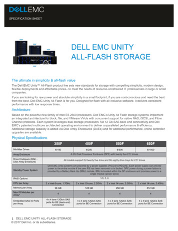
Transcription
Dell EMC Data Domain DD9500 andDD9800 SystemsVersion 6.1Hardware Overview and Installation Guide302-002-887REV. 02
Copyright 2016-2017 EMC Corporation All rights reserved.Published June 2017Dell believes the information in this publication is accurate as of its publication date. The information is subject to change without notice.THE INFORMATION IN THIS PUBLICATION IS PROVIDED “AS-IS.“ DELL MAKES NO REPRESENTATIONS OR WARRANTIES OF ANY KINDWITH RESPECT TO THE INFORMATION IN THIS PUBLICATION, AND SPECIFICALLY DISCLAIMS IMPLIED WARRANTIES OFMERCHANTABILITY OR FITNESS FOR A PARTICULAR PURPOSE. USE, COPYING, AND DISTRIBUTION OF ANY DELL SOFTWARE DESCRIBEDIN THIS PUBLICATION REQUIRES AN APPLICABLE SOFTWARE LICENSE.Dell, EMC, and other trademarks are trademarks of Dell Inc. or its subsidiaries. Other trademarks may be the property of their respective owners.Published in the USA.Dell EMCHopkinton, Massachusetts 01748-91031-508-435-1000 In North America 1-866-464-7381www.DellEMC.com2Data Domain DD9500 and DD9800 Systems 6.1 Hardware Overview and Installation Guide
CONTENTSFigures5Tables7Chapter 1Revision history9Planning and Site Preparation11Tools and supplies needed.12Safety information. 12Chapter 2Hardware Overview15System features.16System specifications. 16DD9500/DD9800 front panel.18Front LED indicators. 18Solid State Drives (SSD). 21Rear panel. 22Power supply units. 23Management module. 23Rear LED Indicators. 24Available I/O modules. 26Ethernet I/O modules. 27Fibre Channel (FC) I/O modules. 27SAS I/O modules. 27I/O module slot assignments. 27Slot Addition Rules. 29Internal System Components. 30DIMM Modules. 32Cooling Fans. 32Storage capacity. 33Chapter 3Install the System in the Rack37Unpack the system.38Install the rack brackets. 38Shelf brackets and cable management assembly. 38Install rail brackets on the Data Domain racks (for square or roundhole racks).40Install rail brackets using the adapter hardware (for threaded holeracks). 43Install the DD9500/DD9800 system into a rack. 45Mount the cable management assembly. 47Install the Data Domain cable management assembly (CMA).47Installing the expansion shelves into the racks.49Chapter 4Connect Cables and Power on51Connecting the expansion shelves and the controllers. 52Data Domain DD9500 and DD9800 Systems 6.1 Hardware Overview and Installation Guide3
CONTENTSES30 cable information. 52Connecting multiple ES30 shelves to the DD9500 /DD9800 system. 56DD9500 /DD9800. 56DD9500 /DD9800 with HA (one rack). 58DD9500 /DD9800 with HA (two racks).60DD9500 /DD9800 with DD Cloud Tier (Single node or HA).63DD9500 /DD9800 with ERSO. 66DS60 cable information. 69Connecting multiple DS60 shelves to the DD9500 /DD9800 system. 70DD9500 /DD9800. 70DD9500 /DD9800 with HA. 73DD9500 and DD9800 with DD Cloud Tier (Single node). 75DD9500 and DD9800 with DD Cloud Tier (HA). 76DD9500 and DD9800 with ERSO. 80Connecting the HA interconnect.81Connect data cables on both nodes.82Power on the systems. 83Install the bezel. 84Chapter 5Configure System For Use85Enable administrative communication.86Accepting the End User License Agreement (EULA). 88Run the configuration wizard.88Configuring the network.88Configuring additional system parameters.90Configure HA for new installations. 914Data Domain DD9500 and DD9800 Systems 6.1 Hardware Overview and Installation Guide
ing about lifting the system.13Front panel components.18Service LEDs.19Power button. 20Front LEDs. 20SSD drives. 21Features on rear of chassis.22Serial number tag location. 22Four power supplies.23Management module. 241000BaseT Ethernet ports. 24Rear LEDs. 25Power supply LEDs.25Location of NVRAM and I/O modules. 27SP module . 31Releasing a memory riser . 31Open fan tray. 32Warning about lifting the system. 38Rail bracket inside. 39Rail bracket outside. 39Cable management assembly (CMA).40Insert screw in the back. 41Insert screw in the front. 42Attach bracket to front of rack.42Adapters. 43Attaching the front rail with the screw. 44Attach front rail adapter . 45Warning about lifting the system. 45System on a rack . 46Location of serial number tag.47Data Domain CMA back . 48Data Domain cable management assembly back inside. 48Rear of the rack mount rail . 49Node 0 SAS I/O module to ES30 host port connector. 53Node 1 SAS I/O module to ES30 expansion port connector.54Cables for ES30 to ES30 connections. 55Cabling for base DD9500 /DD9800 systems. 58Cabling for HA DD9500 /DD9800 systems in one rack.60Cabling for HA DD9500 /DD9800 systems in two racks.63Cabling for DD9500 /DD9800 systems with DD Cloud Tier (Single node or HA) . 66Cabling for DD9500 /DD9800 systems with ERSO . 68SAS I/O module to DS60 connector.69Cabling for base DD9500 and DD9800 systems.72Cabling for HA DD9500 and DD9800systems. 74Cabling for DD9500 and DD9800 systems with DD Cloud Tier. 76Cabling for HA DD9500 and DD9800 systems with DD Cloud Tier.79Cabling for DD9500 and DD9800 systems with ERSO. 81DD9500/DD9800 HA interconnect.82Power LED and power button. 87Data Domain DD9500 and DD9800 Systems 6.1 Hardware Overview and Installation Guide5
FIGURES6Data Domain DD9500 and DD9800 Systems 6.1 Hardware Overview and Installation Guide
7Document revision history. 9DD9500/DD9800 system features.16DD9500/DD9800 system specifications. 16Front panel LED status indicators. 21Rear LED status indicators. 25Physical to logical port mapping example. 26DD9500 and DD9800 I/O module slot assignments. 28I/O module slot population rules. 29DD9500/DD9800 memory configurations. 32DD9500/DD9800 storage capacity. 33DD9500/DD9800 with ES30 SAS shelves. 34DD9500/DD9800 with DS60 shelves. 35Cables for node 0 to ES30 shelf loop.53Cables for node 1 to ES30 shelf loop. 54ES30 to ES30 cable options. 55Primary node cabling instructions.59Standby node cabling instructions.59Primary node cabling instructions. 61Standby node cabling instructions.61Primary node cabling instructions.64Standby node cabling instructions. 64Cables for node 0 and node 1 to DS60 shelf loop. 69Primary node cabling instructions. 73Standby node cabling instructions. 73Primary node cabling instructions. 77Standby node cabling instructions. 77Communications settings. 86Data Domain DD9500 and DD9800 Systems 6.1 Hardware Overview and Installation Guide7
TABLES8Data Domain DD9500 and DD9800 Systems 6.1 Hardware Overview and Installation Guide
Revision historyTable 1 Document revision historyRevisionDateDocumentpart une 2017302-002-887,Rev. 016.1Editorialrevisions01October 2016302-002-887,Rev. 016.0Initial publicationRevision history9
Revision history10Data Domain DD9500 and DD9800 Systems 6.1 Hardware Overview and Installation Guide
CHAPTER 1Planning and Site PreparationllTools and supplies needed. 12Safety information. 12Planning and Site Preparation11
Planning and Site PreparationTools and supplies neededThese tools and supplies may be helpful for the installation and setup tasks for DataDomain systems.lNull modem cable (DB-9 female to female), plus sparelUSB-to-DB-9 serial (male connector) converter cable if the laptop does not have aserial port, plus sparelPower adapter, C13 to NEMA 5–15 (if based in North America), or a power cordfor your laptop power adapter with a C13 plug, so that you can power your laptopfrom a rack PDUlAntistatic wrist strap and conductive foam padlScrewdrivers:nPhillips #2 with a 12 in. or longer bladenPhillips #2 (standard-length blade)nPhillips #1nFlat head 3/16 in.nFlat head 1/4 in.nTorx T10lFlashlightlNeedle nose plierslDiagonal wire cutters (for cutting tie wraps)l2 GB or greater USB flash memory drivelTie wraps (4 in. and 8 in.)l(recommended) Roll of 5/8 inch Velcro cable tie material (3M ScotchmateSJ-3401 or similar)Safety informationCAUTIONlIf the system is used in a manner not specified by the manufacturer, theprotection provided by the equipment may be impaired.lThe RJ45 sockets on the motherboard, PCI cards, or I/O modules are forEthernet connection only and must not be connected to atelecommunications network.Review this list of important safety recommendations.12lAll plug-in modules and blank plates are part of the fire enclosure and must beremoved only when a replacement can be added immediately. The system mustnot be run without all parts in place.lA DD9500/DD9800 system must be operated only from a power supply inputvoltage range of 200–240 VAC and 50–60 Hz. ES30 shelves use 100-240 VAC and50–60 Hz. DS60 shelves use 200–240 VAC and 50–60 Hz.Data Domain DD9500 and DD9800 Systems 6.1 Hardware Overview and Installation Guide
Planning and Site PreparationlEach component is intended to operate with all working power supplies installed.lProvide a suitable power source with electrical overload protection.lA safe electrical earth connection must be provided to each power cord. Checkthe grounding of the power sources before applying power.lThe plug on each power supply cord is used as the main device to disconnectpower from the system. Ensure that the socket outlets are located near theequipment and are easily accessible.lPermanently unplug the unit if you think it is damaged in any way and beforemoving the system. A DD9500/DD9800 system includes four power supplies. Tocompletely remove system power, you must disconnect all four power supplies.lThe power connections must always be disconnected prior to removal orreplacement of a power supply module from any of the components in the system.lA faulty power supply module must be replaced within 24 hours.lDo not lift system components by yourself. A DD9500/DD9800 system weighs upto 117 lbs (53.2 kg), an ES30 expansion shelf weighs up to 68 lbs (30.8 kg), and aDS60 shelf weighs up to 225 lbs (90.7 kg).CAUTIONData Domain systems are heavy. Use at least two people or a mechanical liftto move any system.lDo not lift an expansion shelf by the handles on any modules. The handles are notdesigned to support the weight of the populated shelf.lTo comply with applicable safety, emission, and thermal requirements, coversmust not be removed and all bays must be fitted with plug-in modules.lOnce removed from the shipping box, it is ok to lift the DD9500/DD9800 systemor the chassis with the four handles to place in a rack. You will need to remove thehandles from the sides before sliding the system in the rack. The four handlesshould be saved for later use.Figure 1 Warning about lifting the systemlLoa
Dell EMC Data Domain DD9500 and DD9800 Systems Version 6.1 Hardware Overview and Installation Guide 302-002-887 REV. 02