Transcription
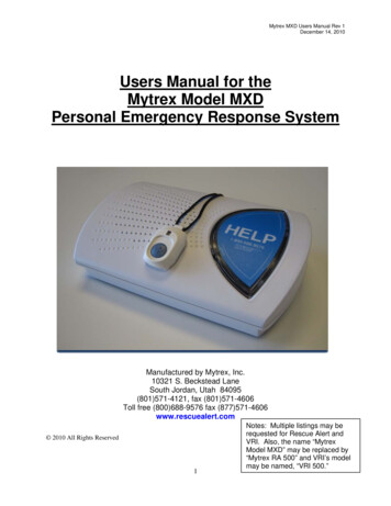
Mytrex MXD Users Manual Rev 1December 14, 2010Users Manual for theMytrex Model MXDPersonal Emergency Response SystemManufactured by Mytrex, Inc.10321 S. Beckstead LaneSouth Jordan, Utah 84095(801)571-4121, fax (801)571-4606Toll free (800)688-9576 fax (877)571-4606www.rescuealert.com 2010 All Rights Reserved1Notes: Multiple listings may berequested for Rescue Alert andVRI. Also, the name “MytrexModel MXD” may be replaced by“Mytrex RA 500” and VRI’s modelmay be named, “VRI 500.”
Mytrex MXD Users Manual Rev 1December 14, 2010IntroductionCongratulations! You have chosen the Mytrex MXD Personal Emergency Response System(PERS) system, which you have obtained through the following service provider:[Provider’s nameProvider’s addressBusiness Toll free numberResponse Center Toll Free Number (if different from business number)Fax NumberEmail addressWeb site]The MXD has been created to provide you comfort, reassurance, and peace of mind by making itpossible for help to be just a touch of a button away.Pressing your waterproof PHB will immediately activate the MXD PERS unit. Within seconds,your response center will be notified of your need for assistance. When a call for help isreceived, the response center’s computers provide an attendant with all of your personalinformation. The attendant will talk to you through the MXD unit’s speakerphone. Theattendant will then telephone your family, friends, or emergency services based on the type ofassistance you need. Even if you cannot hear or speak to the attendant, help will be summonedfor you.The MXD unit is fast and simple to install. Your service provider’s representative may connectthe MXD unit during an installation visit, you may elect to do it yourself, or you may ask afriend or relative to install it for you.To ensure that you always receive the fastest response time possible, it is very important that youdo the following: Notify your service provider of any changes that should be made to your personalaccount information. You can update your account by calling your service provideror by pressing your PHB and relaying the information to the attendant over thespeakerphone. Your response center needs to be aware of changes to your address,telephone number, responder information, medical history, allergies, doctor information,hidden key location, and other information that you wish to have on file. Test your MXD unit at least once a month by pressing your PHB. Always wear your PHB!2
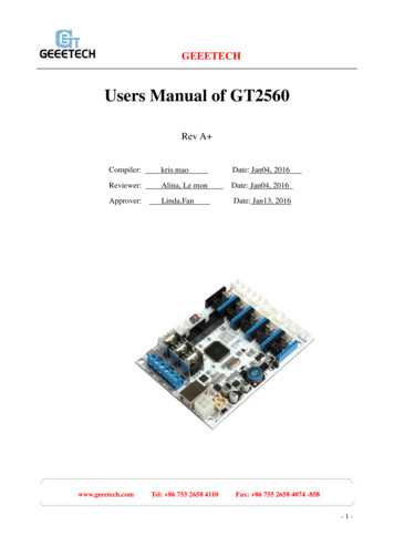
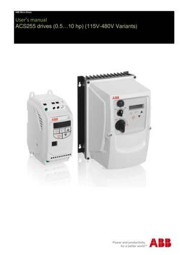
Mytrex MXD Users Manual Rev 1December 14, 2010This User’s Manual has been designed to help you make the most of your MXD PERS system. Ifyou have any questions or concerns after reading this manual, please contact your serviceprovider.MXD PERS Equipment DescriptionOVERVIEWYour PERS system consists of the MXD base unit, telephone cord, and one or more Personal HelpButtons (PHBs) or other accessories. The MXD unit incorporates several important features, including: Compatible with Voice over IP (VoIP) telephone circuits in addition to standard telephonetechnology When enabled, interactive voice messages from the unit when the unit is calling the responsecenter and during certain setup operations PHB detection ranges up to 600 feet from the base unit Simplified base unit buttons and indicator lights State of the art electronics Capacity to remember many PHB and other device codesPower Blockand Cord (notremovable frombase unit)Base UnitHelp ButtonSTATUSLightFigure1. MXD Base Unit and Power Cord3
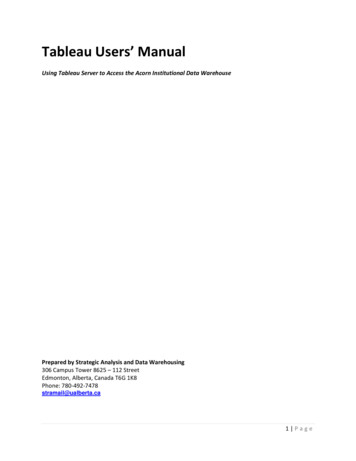
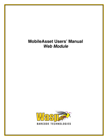
Mytrex MXD Users Manual Rev 1December 14, 2010WALL (large)Jack -- Insertlarge end ofRescue Alerttelephone cordherePHONE (small)Jack -- Insertyour handset’stelephone cordplug hereRESETButtonT/L(Test/Learn)ButtonFigure 2. Rear of MXD Base UnitPlug the largeend into the“Wall” jack on theback of the baseunitPlug the smallend into thetelephone jackon the wallFigure 3.Personal Help Button (PHB)Figure 4. MXD Telephone CordWarning: Before your MXD system is ready for operation, it must be properly installed, have completeda range test, and completed its first call to the response center. See the detailed setup instructions later inthis manual, or for additional information, contact your service provider.BASE UNIT CONTROLS AND INDICATORThe MXD base unit has three push buttons, including the large HELP button on the top of the base unit,and two small buttons on the back of the unit that are used during initial installation and at other times ifneeded. Each button is described below.4
Mytrex MXD Users Manual Rev 1December 14, 2010Base Unit Help Button (Figure 1)Normally, pushing the large blue Help Button on the front of your Rescue Alert base unit causes the unitto send a “Help needed” message to the response center. The Help Button also is used with the T/L buttonto conduct range tests and to program the MXD unit to recognize PHBs or other accessories.STATUS Light (Figure 1)A small STATUS light is located on the lower left edge of the unit’s large “Help” button. The STATUSlight will display steady or flashing lights, in either red, green or orange color, depending on the status ofthe unit. See Page 15 for a more detailed description of the STATUS light signals and their meaning.T/L (Test/Learn) Button (Figure 2)The white T/L (Test/Learn) Button is located on the rear of your MXD unit. It is used to place your MXDunit into special operating modes to conduct PHB range tests, to program PHBs and other accessories,and to allow technical personnel to diagnose problems and adjust the unit.T/L Operating Modes ChartIf the T/Lbutton ispushed:OnceThe base unit will beplaced in the followingmode:RANGE TESTVoice Announcement (ifenabled)Tone Signal (if voice notenabled)“Range Test Mode”One brief toneTwiceMONITOR“Monitor Mode”Two brief tonesThree timesSERVICE“Service Mode”Three brief tonesFour timesReturned to normalmode“System Ready”Two quick tones in rapidsuccessionThe purpose of this mode is:Test the range of the PHB andsearch for areas where the PHBsignal is not detected by thebase unitAllow a technician to listenwhile the unit is dialing andtransferring data. This helpsthe technician troubleshootproblems.Allows a response centerattendant to communicate withthe unit during troubleshootingor re-programmingThe unit is returned to itsnormal mode, ready to processalarm signalsRESET Button (Figure 2)The black RESET button is located on the rear of your MXD unit. Whenever the RESET Button ispressed, your MXD unit will return to its standard operating mode, ready to transmit alarms from thePHB or the Base Unit Help Button if the unit is properly installed. The unit will sound two quick toneswhen it is reset. If voice announcements are enabled the unit will announce, “System Ready.”The RESET Button may also be used to cancel your call for help if your MXD unit is inadvertentlyactivated. To cancel a call for help, the RESET Button must be pressed within 10-15 seconds ofactivation; otherwise, the unit will already be communicating with the response center. The responsecenter is staffed 24 hours a day, therefore, it is best to allow your MXD unit to complete the call and tellthe attendant that you accidentally activated your MXD unit.5
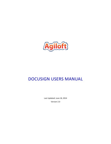
Mytrex MXD Users Manual Rev 1December 14, 2010Personal Help Button (Figure 3)Each MXD unit is supplied with one or more Personal Help Buttons (PHBs). The PHB is a smallwaterproof pendant that may be worn around the neck on a breakaway cord, or may be worn attached to awrist band. When pressed, the PHB sends a “Help needed” radio signal to the MXD base unit, causing itto call the monitoring center. Within a few seconds, an attendant will talk to you through your MXD baseunit’s speaker to determine if help is needed. The PHB transmitter and the base unit receiver are carefullydesigned to ensure that the base unit can detect the PHB’s signal at distances of up to 600 feet away fromthe base unit.Setup GuideYour MXD is designed to work with many different types of telephone technologies, including traditionalPlain Old Telephone Service (POTS), Voice over Internet Protocol (VoIP), cable company telephonesystems, and Digital Subscriber Line (DSL) service. This section provides instructions for setting up theMXD to work with POTS, DSL, and VoIP telephone service. Telephone systems provided by cablecompanies generally require connections similar to POTS telephones. Please contact your serviceprovider if none of the following setups work for your system.Initial Setup steps for Any Type of System:For any of the following setups:1. Locate a live telephone jack with an electrical outlet nearby. The electrical outlet mustnot be controlled by a light switch. Select a location where the MXD unit can be placedon a flat, horizontal surface and where it will be located centrally, in a part of your homethat is used frequently. While it is recommended that the MXD be placed on a flat,horizontal surface, it can be wall mounted if necessary. The MXD unit should be locatedaway from the immediate vicinity of mechanical noise sources, i.e. oxygen generators,electrical equipment, and all appliances such as televisions or stereos.2. If a telephone handset has not been plugged into the telephone jack and used recently,plug a telephone handset into the jack and make a call using the handset to a workingtelephone number. Confirm that the call goes through and that both parties can hear andspeak to one another.3. Unplug the telephone handset cord from the wall jack.System Setup for Locations with Plain Old Telephone Service (POTS)Figure 5 is a general representation of a setup for locations connected to traditional telephone service.6
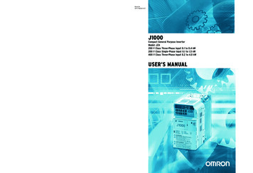
Mytrex MXD Users Manual Rev 1December 14, 20101.2.3.Figure 5. MXD Connections for Traditional (POTS) Telephone ServiceComplete the installation steps common to all setups that are listed on Page 6.Plug your telephone handset cord into the jack on the back of the MXD unit marked“PHONE”. If your home is equipped with DSL service, see configurations on page8.Find the telephone cord that was shipped with your MXD unit, with a larger modularplug on one end and a smaller modular plug on the other end. Plug the smaller end intothe wall jack, and the larger end into the jack on the back of the MXD unit marked“WALL”.NOTE: When your MXD unit calls the response center, the telephone and anyother device connected to the PHONE jack on the rear of your MXD unit will bedisconnected during the call. This means if this telephone is off hook, your MXDunit can still contact the response center. If there are other extensions of the sametelephone number in your home that are off-hook when your MXD unit needs toplace a call, it will not be able to unless the local telephone company has installed anRJ31X jack or devices called “Line Grabbers” are properly installed on eachtelephone extension. The RJ31X jack allows the MXD unit to disconnect anytelephone in the house that may be in use. IF you elect to have an RJ31X installed,contact your service provider and ask for an RJ31X telephone cord, Mytrex partnumber RA400-RJ31X. If you elect to use Line Grabbers, contact your serviceprovider for ordering and installation instructions.4.Plug the power transformer into an AC outlet. Verify that the outlet is not controlled bya light switch.5.The MXD unit will automatically turn on and announce, “System Ready.” The small“status” light on the lower left edge of the unit’s large “Help” button will show a steadygreen light. This indicates that the unit is connected properly to the telephone circuitand AC power. If the telephone is connected improperly, the unit will announce, “PleaseCheck Telephone Connections.” Please see page 20 for information on the status lightcombinations that will display if the unit is not connected properly to the telephonesystem and electrical power, and for troubleshooting instructions.7
Mytrex MXD Users Manual Rev 1December 14, 20106.Test the range of the PHB to make sure it works throughout your home and yard as needed.It may be helpful to have a second person assist with this range test, with one person stayingby the base unit and the other person walking to all areas of the home and yard with thePHB. To conduct the test: Locate the T/L button located on the rear of the MXD unit. Press and release theT/L button one time. The unit will announce, “Range Test Mode.” Immediately press and hold down the PHB. A steady tone will sound from thebase unit speaker as long as the base unit is detecting the PHB. Walk around the home and yard while pressing the PHB, and check for thesteady tone from the base unit speaker. Check all areas of the home and yard tomake sure that the signal is received. Take note of any “dead zones” in which thetone stops.* To finish the Range Test, stop pressing the PHB and then press the black“RESET” button on the rear of the MXD unit. The unit will announce, “SystemReady.” If needed, relocate the base unit to eliminate dead zones and conduct anotherrange test.*Metal objects, mirrors, aluminum siding, and other construction techniques can prevent the signalfrom reaching the antenna inside your MXD unit. In such cases, there may be a small area in whichyour MXD unit may not respond to your PHB. It may be helpful to relocate your MXD unit, ormove the object that is preventing the signal from being received. Also, electronic devices such asclock radios, televisions, microwaves, and motors in some appliances can cause radio frequencyinterference.7. Initiate your first call to the response center simply by pressing your PHB. The MXDunit will activate and call the response center. The unit will announce, “Calling forHelp,” and when it has connected to the response center will announce, “CallConnected, Please Wait.” An attendant will then answer the call as soon as possible, willwelcome you as a customer, and will give you further information.8. Note: The MXD unit is programmed to automatically call the response center a fewminutes after it has been installed for the first time, if the installer has not alreadyinitiated a first call. This automatic call ensures that the response center is aware of thenew subscriber and knows to be ready to process any alarm calls. The unit usually isprogrammed to make this call 30 minutes after installation, but the unit can beprogrammed for a different delay period.Setup for Telephone Service with DSLIn order to achieve reliable telephone connections with the response center, homes with DSLtelephone/computer service require additional installation steps. In the following sections, we have listedthe three configurations for a successful MXD/DSL installation, in order of commonality.Follow the general installation procedures steps for POTS systems, and also complete one of thefollowing three configurations. Even with these configurations, it is possible that you will need to callyour service provider for more extensive troubleshooting.8
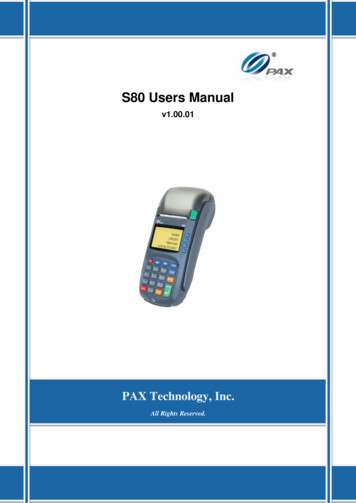
Mytrex MXD Users Manual Rev 1December 14, 20101. Configuration 1: Plug-in DSL filters, supplied by the DSL provider, are installed betweentelephone wall jacks and telephones in the home. If Configuration 1 has been installed in yourlocation, plug a DSL filter into the wall jack and then plug the MXD’s telephone cord into theDSL filter. See Figure 6 below.NOTE: Some DSL filters supplied by DSL providers degrade the signals sent by the MXD tothe response center. If your MXD has problems communicating with the response center,replace the DSL provider’s filter with one from a different supplier. Contact your serviceprovider for assistance in obtaining a high quality DSL filter.Figure 6. MXD Connections for Locations with a Self-Installed DSL Filter2. Configuration 2: The DSL filter is hard wired by the DSL provider. In this instance thelocation does not have self-installed filters on the telephone jacks, and the MXD unit should beconnected in the same manner as for traditional telephone service. See Figure 7 below.9
Mytrex MXD Users Manual Rev 1December 14, 2010Figure 7. MXD Connections for Locations with Hard-Wired DSL Filters(Connections are the same as for standard telephone service)3.Configuration 3. Alternative approach if neither of the above configurations works. If theMXD cannot communicate with the response center using Configurations 1 or 2, you may be able toconnect the MXD unit into a phone jack built into the DSL Modem, which should be located nearyour computer. See Figure 8 below.Figure 8. MXD Connection to DSL ModemSetup for Voice over Internet Protocol (VoIP)Caution: The MXD PERS system is designed to be used with either traditional or VoIP basedtelephone service. Mytrex strongly recommends that a Plain Old Telephone Service (POTS)line be used for any type of alarm system, due to the much higher reliability of POTS.However, increasing numbers of residences now are serviced by VoIP. There are differences inthe quality of service provided by different VoIP providers. VoIP telephone circuits are not asreliable as standard telephone systems for various reasons. For example, many Internetproviders refuse to provide any service level guarantee, and clearly indicate in their contractsthat service may be interrupted at any time. Also, VoIP circuits are dependent on AC electricalservice to the residence, unless the VoIP system is equipped with a backup power supply. Ifyour telephone service experiences service interruptions, you may not be able to use your MXDto contact your monitoring center. For these reasons, your VoIP provider should be chosencarefully. Please evaluate the risks of not having your phone service available as part ofmaking the decision whether or not to use VoIP telephone technology. Mytrex, Inc. will notassume any responsibility for alarms that are not received by the response center due to failuresor interruptions in any telephone system used by the subscriber.The MXD system is connected to a VoIP telephone circuit in the same manner as when a standardtelephone circuit is used, and usually no technical adjustments are required. However, sometimes10
Mytrex MXD Users Manual Rev 1December 14, 2010VoIP systems are installed in a home in a way that one or more wall jacks are not in service, and thatsituation can cause confusion when first installing the MXD unit. Connect and verify that your MXDsystem is connected to an operating VoIP line as follows:1.Complete the initial installation steps described on Page 6, which are common to alltypes of installations.2.Find the telephone cord that was shipped with the MXD unit, with a larger modular plugon one end and a smaller modular plug on the other end. Plug the smaller end into thewall jack, and the larger end into the jack on the back of the MXD unit marked“WALL”.3.Plug the telephone handset cord into the jack on the back of the MXD unit marked“PHONE”. Lift the telephone handset receiver that has been connected to the back ofthe MXD unit, and confirm that there is a dial tone to verify that the MXD telephonecord and the telephone handset cord are properly connected.4.If no dial tone is present, check the connections again and correct any problems.5.After connection to VoIP has been achieved, continue with steps 3 - 7 of the SystemSetup for Locations with Plain Old Telephone Service (POTS). See Figure 9 below.Figure 9. MXD Connection to Voice over IP (VoIP) Telephone ServiceFrequently Asked QuestionsHow can the MXD help me to stay at my home and be safe?The MXD allows you to call for help, even if you are alone and cannot reach or use the telephone.Simply press the PHB and your MXD unit will call the response center where your unit will be11
Mytrex MXD Users Manual Rev 1December 14, 2010identified and connected to a trained attendant. Even if you cannot communicate with your responsecenter, attendants are trained to treat every received alarm as a call for help until they are sure thatyou are okay. Simply press your PHB to activate your MXD unit at any time.Is my Personal Help Button (PHB) waterproof?Yes. You
Mytrex MXD Users Manual Rev 1 December 14, 2010 5 Base Unit Help Button (Figure 1) Normally, pushing the large blue Help Button on the front of your Rescue Alert base unit causes the unit to send a “Help needed” message to the response center. The Help Button also is used with the T/L button