Transcription
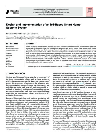
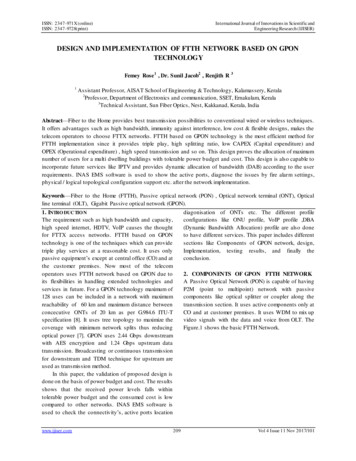
ISSN: 2347-971X (online)ISSN: 2347-9728(print)International Journal of Innovations in Scientific andEngineering Research (IJISER)DESIGN AND IMPLEMENTATION OF FTTH NETWORK BASED ON GPONTECHNOLOGYFemey Rose1 , Dr. Sunil Jacob2 , Renjith R 31Assistant Professor, AISAT School of Engineering & Technology, Kalamassery, Kerala2Professor, Department of Electronics and communication, SSET, Ernakulam, Kerala3Technical Assistant, Sun Fiber Optics, Nest, Kakkanad, Kerala, IndiaAbstract—Fiber to the Home provides best transmission possibilities to conventional wired or wireless techniques.It offers advantages such as high bandwidth, immunity against interference, low cost & flexible designs, makes thetelecom operators to choose FTTX networks. FTTH based on GPON technology is the most efficient method forFTTH implementation since it provides triple play, high splitting ratio, low CAPEX (Capital expenditure) andOPEX (Operational expenditure) , high speed transmission and so on. This design proves the allocation of maximumnumber of users for a multi dwelling buildings with tolerable power budget and cost. This design is also capable toincorporate future services like IPTV and provides dynamic allocation of bandwidth (DAB) according to the userrequirements. INAS EMS software is used to show the active ports, diagnose the issues by fire alarm settings,physical / logical topological configuration support etc. after the network implementation.Keywords—Fiber to the Home (FTTH), Passive optical network (PON) , Optical network terminal (ONT), Opticalline terminal (OLT), Gigabit Passive optical network (GPON).1. INTRO DUCTIO NThe requirement such as high bandwidth and capacity,high speed internet, HDTV, VoIP causes the thoughtfor FTTX access networks. FTTH based on GPONtechnology is one of the techniques which can providetriple play services at a reasonable cost. It uses onlypassive equipment’s except at central office (CO) and atthe customer premises. Now most of the telecomoperators uses FTTH network based on GPON due toits flexibilities in handling extended technologies andservices in future. For a GPON technology maximum of128 uses can be included in a network with maximumreachability of 60 km and maximum distance betweenconcecutive ONTs of 20 km as per G.984.6 ITU-Tspecification [8]. It uses tree topology to maximize thecoverage with minimum network splits thus reducingoptical power [7]. GPON uses 2.44 Gbps downstreamwith AES encryption and 1.24 Gbps upstream datatransmission. Broadcasting or continuous transmissionfor downstream and TDM technique for upstream areused as transmission method.In this paper, the validation of proposed design isdone on the basis of power budget and cost. The resultsshows that the received power levels falls withintolerable power budget and the consumed cost is lowcompared to other networks. INAS EMS software isused to check the connectivity’s, active ports locationwww.ijiser.com209diagonisation of ONTs etc. The different profileconfigurations like ONU profile, VoIP profile ,DBA(Dynamic Bandwidth Allocation) profile are also doneto have different services. This paper includes differentsections like Components of GPON network, design,Implementation, testing results, and finally theconclusion.2. COMPONENTS OF GPON FTTH NETWORKA Passive Optical Network (PON) is capable of havingP2M (point to multipoint) network with passivecomponents like optical splitter or coupler along thetransmission section. It uses active components only atCO and at customer premises. It uses WDM to mix upvideo signals with the data and voice from OLT. TheFigure.1 shows the basic FTTH Network.Vol 4 Issue 11 Nov 2017/101
ISSN: 2347-971X (online)ISSN: 2347-9728(print)International Journal of Innovations in Scientific andEngineering Research (IJISER)2.2 Optical Network Terminal (ONT)It is an active component used at customer premiseswhich converts optical to electrical signals. ONU/ONTrepresents the single customer where they will get thetriple play application. H640 series GPON ONT areused. It is capable of having carrier class VoIPtelephony supporting both MGCP and SIP protocols,Flexible VLAN tagging support, QoS for trafficprioritization and bandwidthmanagement, IGMPsupport for IPTV applications. Its specifications aregiven in table 2.Table 2: H640 Series GPON ONTFigure 1: FTTH Network [7]2.1 Optical Line Terminal (OLT)It is the most important part of the network, where theelectrical signal from the service provider’s equipmentare converted into optical signals and given to thefeeder network. The mode of transmission from ONT isbroadcasting [8] from where it sends GEM framesthrough the GEM port with GEM port IDs It is capableof having Multi-service chassis for FTTx deployments,Supports a variety of service types, Non-blockingarchitecture with & Routing within distributedarchitecture, scalability and line rate performance, Fullelectrical and optical redundancy Outstandingscalability and line rate performance, Real-timenetwork traffic monitoring and analysis .V8240 GPONOLT is used. Specifications are given in the table 1.Table 1: V8240 GPON OLT Specifications.Flash MemorySDRAMDimensions (W xH x D)Switching CapacityPower Voltage ACtypeDC typeOperating TempSIU (SubscriberInterface Unit)NIU (NetworkInterface Unit)SFU (SwitchingFabric Unit)www.ijiser.com72 MB1 GB17.1 x 12.2 x11.2 in (434 x310 x 285 mm)296Gbps100-240VA C,50/60Hz-48/60VDC32 to 122 F (0to 50 C)10 slotsServiceInterface4 10/100Base-TX ports (RJ45)2 POTS ports (RJ11)1 RF video port (F-connector)UplinkInterfaceOperating TempStorageTempInputDimensions (W xH xD)1 GPON port (SC/APC type)32 to 104 F (0 to 40 C)-4 to 140 F (-20 to 60 C)100-240VA C Excluding bracket:10.24 x 2.05x 7.87 in (260 x 52 x 200 mm) Including bracket, wallmounting:10.51 x 2.60 x 7.87 in(267 x 66 x 200 mm) Excluding bracket, desktopmounting: 10.24 x 2.80 x 7.87in (260 x 71 x 200 mm)2.3 SplitterSplitters are used to physically split the fiber to numberof fibers; to couple same or different information’s to Nusers. MxN planar splitters are used which is based onplanar light wave circuit (PLC) technology and highprecision alignment. MxN splitters can split or combinelight from one or two fibers into N outgoing fibersuniformly over a wide spectral range with ultra-lowinsertion loss and low polarization dependent loss. Withupto 64 output ports, these splitters are ideal for highdensity split applications like Fiber To The Home(FTTH) networks, FTTx Deployments Optical CATVNetworks, CWDM and DWDM Systems , Passive2 slots2 slots210Vol 4 Issue 11 Nov 2017/101
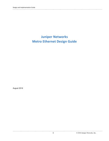
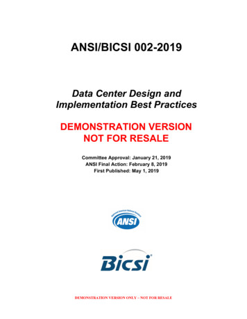
ISSN: 2347-971X (online)ISSN: 2347-9728(print)International Journal of Innovations in Scientific andEngineering Research (IJISER)Optical Networks, Fiber Communication SystemsTelecom, LANs. It has the features like Low InsertionLoss, Ultra broadband performance (1260 –1630nm),Low PDL and PMD, Stable towards thermalvariations, Superior port to port uniformity. A splittertype is shown in Figure.2Figure 3: EDFA View 5.0 front viewFigure 2: PLC splitter with Ribbon fiber2. 4 EDFAErbium Doped Fiber Amplifier (EDFA) is used toamplify the video signal from the cable TV serviceprovider and feed into WDM. EDFA CATV (cable TV)is used which signify different models of endless poweroutput booster EDFA used in CATV networkapplication as C band signal promoter in opticaldomain. It has continuous circuit parameter monitoringfor safe operation, auto shutdown for safe guard ofinternal units, future proof upgradeable modules, freemonitoring software, and continuous display of opticalpower. EDFA View 5.0 is the software provided withthe system. By installing this software & interfacingEDFA with the PC, the system performance parameterslike the input power, output power, gain can bemonitored. The entire pump laser related parameters aredisplayed for easy trouble shooting of the system. Theinput power is 1.566 dBm ,output power and gainobtained are 18.043dBm, 16.526dB respectively .Thesoftware output is shown in Figure.3.www.ijiser.com2113. DESIGNThe design includes the steps involved in the initialstage of FTTH network design, splitter allocationdesign to each floor, overall FTTH network from OLTto an ONT, Power budget calculation, link losscalculation, cost calculation, power meter testing resultsat initial checking stage. The design flow chart showingthe each stage of developing an optimum design isgiven in Figure. 4. The cost and power budget are themain two parameters considered while designing. Thecustomer requirements includes :High bandwidth dataservice, National, international voice calling facilitieson all rooms, VoIP service and video phone facilities inall rooms, WiFi coverage in all common areas ,CATVservices in all rooms, IPTV service provisions in allrooms in near future, Dedicated bandwidth allocation asper requirement, multiple service provider facility, fordoctor’s room : data and voice, for each floor thereshould be WiFi ONT , data point and voice in nursesroom, for patients room there should be ONT terminalthat supports IPTV in future along with otherconnections.Vol 4 Issue 11 Nov 2017/101
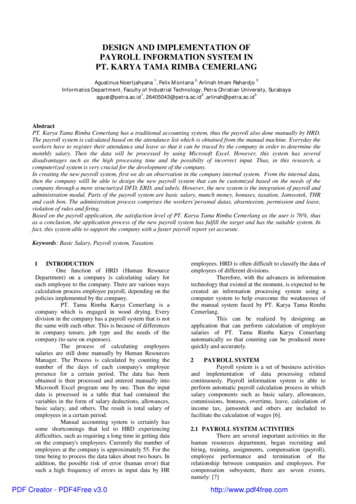
ISSN: 2347-971X (online)ISSN: 2347-9728(print)International Journal of Innovations in Scientific andEngineering Research (IJISER)The splitter allocation in each floor is designedconsidering the insertion losses, power transmitted andreceived at OLT and ONT. The power and the lossesare calculated using the power meter testing. Thesplitter allocation design is shown in Figure.6 which isdrawn using coral drawing and power ,insertion losses(IL) calculated are given in table 3. This design isflexible to accommodate future extensions to eachfloor. Even though the design is made upto 9th floor ,the implementation is performed only upto 5th floor asper the customer requirement.Figure 4: Design Flow ChartFigure 6: Splitter allocation designThe FTTH network design showing thetransmission from OLT to one ONT is shown inFigure.5. The video signals are given to EDFA wherethere is an isolator to have the transmission only in onedirection and transmitted at 1550nm and the voice , dataare given to OLT to convert to optical signal andtransmitted at 1310nm.WDM mixes these two signalsfrom EDFA and OLT.Table 3: Power and Losses in the ComponentsFigure 5: FTTH network designwww.ijiser.com212Vol 4 Issue 11 Nov 2017/101
ISSN: 2347-971X (online)ISSN: 2347-9728(print)International Journal of Innovations in Scientific andEngineering Research (IJISER)Power budget, link loss and cost are calculated usingthe following equations:Rx power at ONT min tx of OLT – (patch cord Amax IL patch cord B IL splitter max IL riser cable(C) IL drop cable (D) IL ).Rx power at ONT tx power at OLT – ( all lossesalong the path from OLT to ONT).Patch cord A : OLT to WDM and splitterPatch cord B : splitter to patch panel.Link loss total length of fiber x attenuation (dB/km) no. of splices x splicing loss no. of connector xconnector loss.Total loss Link loss safety margin (3 dB).Total cost active component cost passivecomponent cost labor cost including implementationand maintenance cost.operative room, Second floor: Doctor’s room, nurse’sroom, consult room, nuero lab, Urodynamic, Third floor: not assigned, Fourth floor : consult room, Fifth Floor :Pathologists, lab in charge room, staff room, reception,lab tech/data entry, serology lab, TTD lab ,cytopathologist’s room. The implementation procedureis shown in the Figure. 7 . For testing, the methods usedare OTDR and LSPM. Optical Time DomainReflectrometry (OTDR) will launch the light into thenetwork and it will used to measure the total length ofthe fiber, loss of fiber, connector, splice, bent positionsand break point detection by using any one of thefollowing output trace, table and summary. It can’t beused for power measurement. Figure. 8 shows theOTDR testing. Light source and power meter (LSPM)testing is a type of testing which uses a light source aslaser and power meter to test the loss and power in theequipments. Figure.9 shows the LSPM testing.Using these equations, the results are shown intable 4. The number of splices and connectors in eachlink are 4 and 9 respectively. Standard values of spliceloss and connector loss are taken which is equal to0.3dB/km and 0.75 dB respectively. Using this link loss 7.168 dB & total loss 10.168 dB. Only at OLT weuse the connector type as SC-PC and all the othersections SC-APC is used. Transmit power for ONT andOLT are 1.5 dBm and the maximum tolerable powerreceive is -28 dBm.Table. 4 Received power levels in ONT4. IMPLEMENTATIONThe optimal design leads to implementation of theFTTH network. The design is done for 9 floorsincluding the future works. This is a green field projectfor the implementation of FTTH network based onGPON in a new building which consists of :GroundFloor : MRI scan, consult, reception, First floor:endoscopy , nurse’s room, ICU, consult, pre/postwww.ijiser.com213Figure 7: Implementation flow chartNoise M210 OTDR , a product of AFL (AmericanFugikura Ltd ) , Fugikura 80S splicer and F2H product,FHP1 series of power meter were used for OTDRtesting, splicing and LSPM testing. Figure.10 shows thespicing.Vol 4 Issue 11 Nov 2017/101
ISSN: 2347-971X (online)ISSN: 2347-9728(print)International Journal of Innovations in Scientific andEngineering Research (IJISER)Figureure 11: ONU profileFigure 8: OTDR testing.ONU profile will create a profile for each ONUwhich includes Traffic profile to handle the trafiic fromeach ONT , VoIP ( voice over IP) profile whichprovides voice over IP including the POTS ( Plain OldTelephone Service), DBA profile will allocatebandwidth dynamically at every milli sec as per thecustomer requirement.Figure 9: LSPM testingFigure 10: SplicingAfter implementation Profile configurations for eachONU is done. The categories of profile configurationsare given in Figure. 11. Each profile configurationscommands are run in hyperterminal of Ubundu andusing Ethernet port it is connected to NIU (NetworkInterface Unit) of OLT. Multicast profile is for havingIPTV which is considered for the future work.Performance Management (PM) is not performed here,it is mainly meant for performance monitoring andbandwidth usage analyzing used by the serviceproviders.www.ijiser.com2145. RESULTSThe results include profile Configuration results,Received power results, INAS EMS results and totalcost acquired result. From the profile Configurationresult it is clear that all the services are successfullyconfigurated and the received power results shows thatthe received power at each ONT is within the tolerablevalue. The INAS EMS shows the active GPON OLTports with green light indication, Topologicalinformation, fault locations and its indication and so on.All these results in INAS EMS can be viewed instead ofgoing for Hyperterminal profile configurations. Figure.12 shows the received power level in putty software andFigure 13: show the details of power levels, distanceand ID number of each ONT. INAS EMS Viewer resultis shown in Figure. 14. The calculated cost result ofproposed design is shown in Figure 15, it is about1,36,2694 rupees and the cost of other design with 2x32splitter at CO is shown in Figure 16.It is clear that forany other design the cost is high (14 lakh) due to theincrease in patch cord, indoor cables and labor worksuch as splicing, laying etc. Even the copper networkhas high cost of implementation since it needs hugeamount of copper for video, voice and data separatelyas well as the maintenance cost needed per year iscomparatively high.Vol 4 Issue 11 Nov 2017/101
ISSN: 2347-971X (online)ISSN: 2347-9728(print)International Journal of Innovations in Scientific andEngineering Research (IJISER)Figure 12: Received Power Levels in PuttySoftwareFigure 14: INAS EMS ViewerFigure 15: ONU ConfigurationFigure 13: Received Power Levels of Each ONTFigure 16: Cost Calculated of Proposed Designwww.ijiser.com215Vol 4 Issue 11 Nov 2017/101
ISSN: 2347-971X (online)ISSN: 2347-9728(print)International Journal of Innovations in Scientific andEngineering Research (IJISER)Figure 17: Cost Calculated for 2x32 SplitterDesignFigure 19: FTB with Splitter6. CONCLUSIONThe results shows the above mentioned design of FFTHnetwork based on GPON technology is an optimumdesign which has tolerable power budget and the cost ofimplementationof thisparticular design iscomparatively low than the other network designs. It isproven that the above design can include extendedversions of technology and services like IPTV in future.7. ACKNOWLEDGMENTThis work described in this paper is carried out with thesupport of SFO (Sun Fiber Optics) Technologies,NeST, DASAN Networks, funded by Sunrise Hospital ,Kakkanad, Kerala, India. This work was supported bySun Fiber Optics, a NeST Group Company, DASANNetworks and Funded by Sunrise Hospital , Kakkand ,Kochi, Kerala, India.Figure 20: WiFi ONTREFERENCES[1]S. Chatzi et al., ―Techno-economic comparison ofcurrent and next generation long reach optical accessnetworks‖, in 9th conference on TelecommunicationsInternet and M edia Techno Economics (CTTE),IEEEConference publications,pp.1-6,2010.S.Kulkarni and M . El-Sayed, ―FTTH-Based BroadbandAccess Technologies: Key Parameters for CostOptimized Network Planning‖,in Bells Labs TechnicalJournal,vol.14,no.4,2010.[3] A.Ouali and K.F. Poon, ―Optimal Design ofGPON/FTTH networks using M ixed Integer tions(NOC),IEEE9thInternationalConference, 2011.[2]Figure 18: Central Officewww.ijiser.com216Vol 4 Issue 11 Nov 2017/101
ISSN: 2347-971X (online)ISSN: 2347-9728(print)[4]International Journal of Innovations in Scientific andEngineering Research (IJISER)J.Segarra et al., ―Planning and Designing FTTHNetworks: Elements,Tools and Practical Issues‖, in 14 thInternational Conference on Transparent OpticalNetworks(ICTON),IEEE Conference publications,pp.16,2012.A. Ouali et al., ―FTTH Network Design Under PowerBudget Constraints‖, in IFIP/IEEE InternationalSymposium on Integrated Network management(IM2013),pp.748-751,2013.[6] D.J. Kadhim and N.A.R.Hussian, ―Design andImplementation of a practical FTTH tions,vol.72,no.12,June 2013.[5][7]M .M . Al-Quzwini, ―Design and Implementationof aFiber To The Home FTTH Access Network based onGPON‖,inInternational Journal of ComputerApplications,vol.92,no.6,April 2014.[8]ITU-T G.984Specificationswww.ijiser.comGigabitPassive Optical Network217Vol 4 Issue 11 Nov 2017/101
The requirement such as high bandwidth and capacity, high speed internet, HDTV, VoIP causes the thought for FTTX access networks. FTTH based on GPON technology is one of the techniques which can provide triple play services at a reasonable cost. It uses only