Transcription
White PaperRouting at theNetwork EdgeTOOLS TO SCALE AND SECURE THE ACCESSNETWORKIt takes more to build a broadband service network than a great Layer 2 access network,partly because of the simplicity of Ethernet as a Layer 2 networking protocol. Ethernetnetworks do not support full mesh topologies or load balancing capabilities, and theLayer 2 network protocols are not coordinated with the Layer 3 network protocols used inthe wide area networks. Equally important, Layer 2 provides limited options for subscriberand network security and can leave the broadband network vulnerable.Integrating Layer 3 routing into the Layer 2 access network architecture delivers fourmajor benefits for the subscriber service network, including:1.Interconnecting access networks to provide resiliency and avoid costly serviceoutages when fibers are cut2.Leveraging routing protocols to better utilize network capacity and improvenetwork efficiency3.Logically connecting outsourced upstream VoIP services into the local servicedomain without major capital investment4.Implementing a wealth of Layer 3 policy tools to enhance network and subscribersecurityEach of these network architecture choices have direct business benefits that aresometimes as easy to quantify as “100 percent higher network capacity utilization” or“network redundancy where there was none in the past”.
White PaperWhite PaperThe networking advantages and benefits of movingrouting closer to the subscriber edge are clear andcompelling.WHAT IS A BROADBAND SUBSCRIBER SERVICE?There is a common misconception that a Layer 2 access network is the same thing as thebroadband service delivery network. The service network is much more expansive andcan even reach into upstream service providers to connect outsourced services into thelocal service delivery area.The subscriber service can be defined by its two end points. One is the home gatewayrouter, where the subscriber’s private home network connects to the service provider’sLayer 2 access network. At the other end of the subscriber service is the broadbandnetwork gateway (BNG) router, where the Ethernet connection transitions back to aconnectionless IP flow bound for the wide, wild world of the Internet.Between these two end points, the service—an IP flow—crosses over the Layer 2 accessnetwork, is aggregated by Layer 2 and Layer 3 switches, and finally terminates on thenetwork gateway router. The broadband service offers a high-speed internet connectionwhile transiting an infrastructure that is reliable, operationally efficient, and secure for boththe service provider and subscribers.To achieve these objectives, service providers need to leverage the best of Layer 2 andLayer 3.THE RIGHT WAY TO ADD BENEFICIAL ROUTING TO THEACCESS NETWORKIdentifying the optimal architecture for the subscriber service network can be a complextask. Put the two gateway routers too far apart and subscribers will experience increasedlatency as they surf the web. Make the Layer 2 access network too big and it becomessusceptible to broadcast storms; too small and it becomes vulnerable to service outageswhen fiber cuts occur. Thinking of the subscriber service as nothing more than a simpleconnection and opens service providers up to cybersecurity threats and denial-of-serviceattacks.When considered together, Layer 3 networking capabilities make Layer 2 access networksmore reliable, efficient, and secure. The networking advantages and benefits of movingrouting closer to the subscriber edge are clear and compelling.SOLVING FOUR REAL- WORLD PROBLEMS IN LAYER 2ACCESS NETWORKSBy implementing Layer 3 routing capabilities service providers realize several importantbenefits for their Layer 2 access networks. To illustrate these benefits, it is instructive tolook at some typical real-world challenges service providers experience and explain howintroducing specific Layer 3 capabilities can address them.
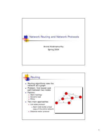
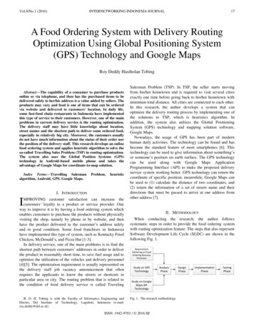
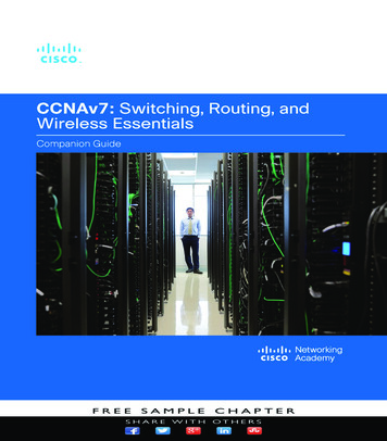
White PaperCONNECTING LARGE LAYER 2 ACCESS NETWORKS“As a result of growth and the merging of two company networks, I have multiple largeLayer 2 access networks that I want to connect and make more efficient.”SOLUTION: IMPROVE SCALE AND EFFICIENCY WITH LAYER 3 ROUTINGFor service providers operating multiple Layer 2 networks, often because of mergers andacquisitions, achieving network efficiencies present a significant challenge, especially asthey look to scale the network to support future subscriber growth.As access networks grow across a geographic area it is common practice to extend theEthernet aggregation network using a simple protection protocol like ITU G.8032 EthernetRing Protection. Unfortunately, while this protocol can be used to build large rings withtens of nodes and even protected sub-rings, the simplicity of Ethernet protection protocolsmeans that there is only one path for traffic to exit the ring. Ethernet protocols preventforwarding loops by blocking ports, so much of the Ethernet network capacity is leftunused, waiting idly in standby mode.Even when large Ethernet rings intersect multiple serving offices with available routers,there is no way to connect the Ethernet rings to the routers because Layer 2 protocols arenot coordinated with Layer 3 protocols. The Layer 3 network does not suffer fromforwarding loops as Ethernet does, but it can also end up with underutilized capacitybecause of “best path” forwarding algorithms.One simple and cost-effective way to address these path protection and capacityutilization challenges is by connecting Layer 2 networks to multiple gateway routers suchas the Calix E9-2 ASM3001. Gateway routers can leverage Layer 3 protocols to overcomethe shortcomings of Layer 2 networking protocols, and at the same time reduce broadcastdomains that can rob a network of bandwidth capacity in the best case and exacerbatedenial of service attacks in the worst.Figure 1 - Layer 3 Routing with VRPP
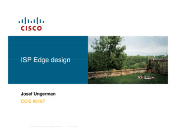
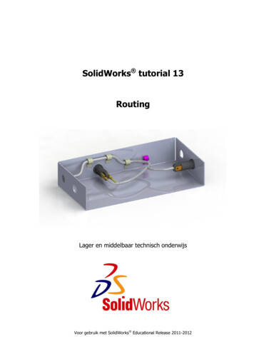
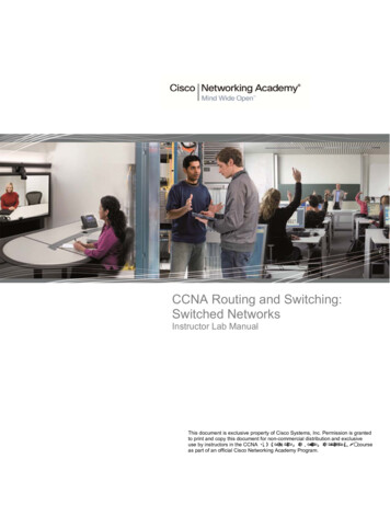
White PaperLAYER 3 ROUTING WITH VIRTUAL ROUTER REDUNDANCY PROTOCOLGateway routers can leverage Virtual Router Redundancy Protocol (VRRP) to create aprotected pair of routers that act as one, automatically creating a shared virtual MAC andIP address for a subscriber’s gateway. As a best practice, the two VRRP-linked gatewayrouters are deployed in geographically diverse locations, connecting to the Ethernet ring intwo locations.The two VRRP routers appear as one logical gateway router to the residential gatewaysthey aggregate, while the Layer 2 network sees the two routers as equally valid forwardingpaths to the wide area network. When a connection to one of the gateway routers goesdown or if the router needs to be taken offline for maintenance purposes, the secondaryVRRP router takes over and advertises its virtual MAC address to the Layer 2 network.For both subscribers and the Layer 2 network, this switchover is seamless and requires nocoordination or cross-layer protocol interworking.EQUAL-COST MULTI-PATH ROUTING (ECMP)Since Layer 2 is a blocking protocol, it is not possible to have every port forwarding on aLayer 2 network. A key advantage of Layer 3 routing, on the other hand, is that it supportsequal cost multi-path (ECMP) forwarding, which allows routers to forward packets to thesame destination over multiple paths with equal priority.With ECMP, the links do not needto be the same speed, as is the case with link aggregation groups leveraging Layer 2 LinkAggregation Control Protocol (LACP). ECMP can use all the network links that areavailable to perform load balancing, increasing utilization of network resources.BRINGING LAYER 2 TRAFFIC TO EXISTINGCENTRALIZED BNG ROUTERS“My network has multiple distributed serving areas. I want a resilient method to bring theLayer 2 access network traffic to existing centralized network gateway routers.”SOLUTION: INCREASE RESILIENCE AND IMPROVE SCALABILITY WITH LAYER 2VPNSService providers with geographically distributed service areas can be challenged to bringaccess traffic from remote Layer 2 access networks to centralized broadband networkgateway (BNG) routers.One effective strategy for addressing this challenge is to tunnel the Layer 2 encapsulatedsubscriber services across a Layer 3 wide area network using Multiprotocol LabelSwitching (MPLS). As shown below, subscriber services from the access network areaggregated by the Label Edge Router (LER) and tunneled over Label Switched Routers(LSR) to the gateway routers.The Layer 2 Virtual Private Network (VPN) – often also called a pseudowire – transportsthe Ethernet frames from the access network unmodified, making it look like the accessnetwork is directly connected to the BNG routers. Layer 3 topology protocols are used tocreate backup paths for the Layer 2 VPNs, providing both path and equipmentredundancy when protected BNG routers are deployed.
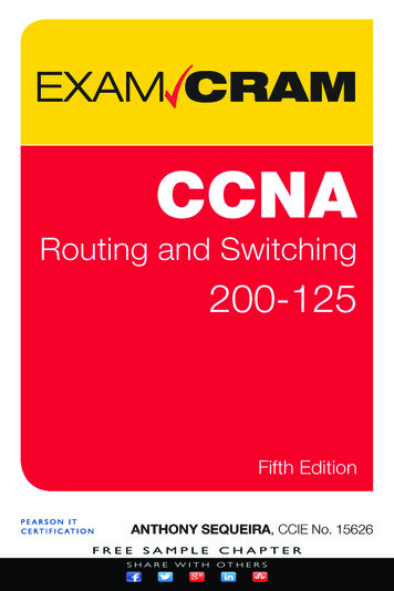
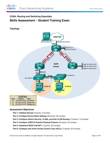
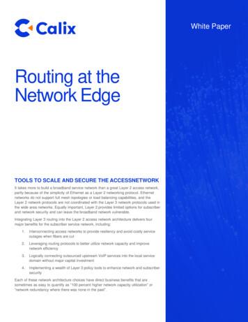
White PaperFigure 2 - Layer 2 VPN with backup pathsGENERATE NEW REVENUE FROM E-LINE AND E-LAN SERVICESThe same MPLS Layer 2 VPN technology used to extend the reach of the BNG routerscan also be used to generate valuable new revenue from business private Ethernet line(E-Line) and Ethernet LAN (E-LAN) services. Multi-location businesses such as a regionalbank could purchase a Layer 2 VPN service to interconnect its banking locations securely.From the bank’s perspective, all the sites are connected to one Layer 2 network. Using aLayer 2 VPN the service provider is transparently transporting the bank’s traffic through anMPLS tunnel over a Layer 3 network without having to change or be aware of the bank’sLayer 3 network configuration.CONNECTING NETWORK SERVICES TO AN UPSTREAMPROVIDER“I use an upstream provider for voice and IPTV. I need a simple method to connect mynetwork services to the upstream provider while making it appear to my gateway routerthat the services are local.”SOLUTION: IMPROVE SERVICE FLEXIBILITY WITH LAYER 3 VPNSMany smaller service providers leverage wholesale providers for VoIP and IPTV services.A common network architecture challenge in this business structure is implementing asimple and cost-effective method for connecting these services down to the local accessnetwork.While it is possible to use a Layer 2 VPN solution to address this challenge, a Layer 3VPN offers additional capabilities and benefits for these inherently trusted IP services.Connecting to an upstream IPTV provider offers a good example.IPTV, by definition, is a Layer 3 multicast service. Leveraging Layer 3 VPNs across thewide area network enables the IPTV multicast protocols to replicate the active channels asefficiently as possible. Unlike the transparent tunnels of a Layer 2 VPN, Layer 3 MPLSVPNs create a virtual private network for the IPTV service without limiting the capabilities
White Paperof Layer 3 multicast protocols. Each router in the Layer 3 VPN creates a private VirtualRouter (VR) space within the router, connecting to other VRs over dynamically routedMPLS connections.A Layer 3 VPN virtual router forwarding table contains only the routes for a particularservice, such as a multi-cast IPTV, VoIP, or high-speed Internet service. The routes inthese Layer 3 VPNs are normally completely isolated from each other but the serviceprovider can flexibly determine which routes should be shared across VRs. To match thelocal services configuration in the BNG router, service providers can keep all IP servicescompletely isolated or allow routes to go between each VPN to allow select services toshare topology information. Layer 3 VPNs provide extensive flexibility in configuration andoperation to match the service provider’s business requirements, creating a servicearchitecture that scales across geography and business boundaries while providingrouting and security segmentation.Figure 3: Layer 3 VPNs for upstream providersOFFER NEW SERVICES WITH LAYER 3 VPNSLike the Layer 2 VPN solution, Layer 3 VPNs also enable new business serviceopportunities. Take the example of a regional health care provider that has its ownenterprise network and wants to be able to connect its offices together without the burdenof administering a wide area network. In a complication to the service provider’s networkarchitecture, it is common for enterprises to havealready assigned their own private IP addresses that may overlap with the serviceprovider’s assigned addresses. Using a Layer 3 VPN with isolated virtual routers, theservice provider ensures that the customer’s IP addresses are isolated and conflict freewithin the broader network. In a Layer 3 VPN, the same IP addresses can be used acrossany number of private networks, offering flexibility and operational efficiency benefits.
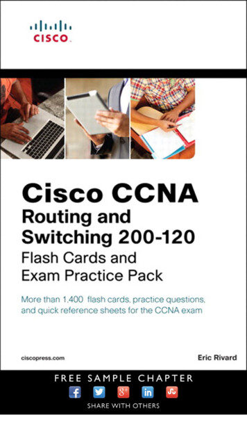
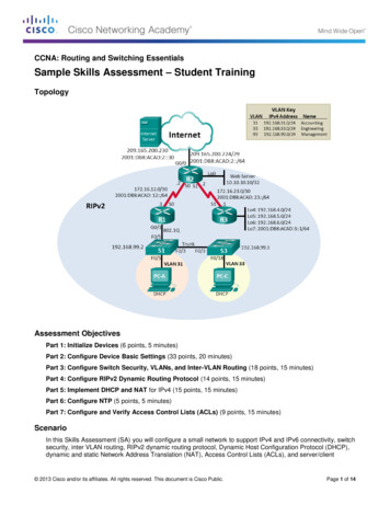
White PaperIMPLEMENTING A CENTRALIZED SECURITY POLICY“I’m concerned that my Layer 2 access network is vulnerable to denial-of-services attacksand exploitation. I want to add an enhanced layer of network security.”SOLUTION: CENTRALIZE SECURITY POLICY WITH LAYER 3Most service providers with Layer 2 access networks have taken advantage of the coresecurity protection measures that Layer 2 provides, such as learning subscriber IP andMAC addresses and locking them to the subscriber port to prevent IP and MAC addressspoofing. Effective as these measures are, additional security tools and threat mitigationoptions are available with Layer 3.As the service delivery network more closely integrates Layer 2 and Layer 3 componentsof a broadband Internet access service, an enhanced level of subscriber awareness anddynamic policy options become available. A subscriber’s IP address can be continuouslymonitored to enforce fair use policies and assign security access policies to service IPflows for both upstream and downstream directions. Threats from the network toward thesubscriber can be prevented using Layer 3 tools, while threats from the subscriber suchas malware- infected IoT devices can be mitigated with other measures.Figure 4: Integrating Layer 3 security with Layer 2 access networksImportantly, Layer 3 policies can be centrally and dynamically administered to quicklyrespond to new cybersecurity threats. The policy can be applied broadly or to an individualsubscriber to mitigate a variety of vulnerabilities.SUPPORTING RAPID SERVICE UPGRADES FOR SUBSCRIBERSThe same central security policy controls can be used for services changes andsubscriber moves. A subscriber may change apartments, but the policy implemented bythe service provider will dynamically re-establish as the subscriber is authenticated on thenetwork. Layer 3 policy controls can also be used to rapidly provision changes tosubscriber services such as on-demand service tier upgrades. To support this request thesubscriber’s service request is authorized centrally and then updated along the end-to-endservice path while the service tier request remains in effect.
White PaperLEARN HOW CALIX CAN HELP SOLVE LAYER 2CHALLENGESThe Calix Intelligent Access Edge Solution brings the benefits of a Layer 3 networkarchitecture, including MPLS Layer 2 and Layer 3 VPNs, to new or existing Layer 2access networks, radically simplifying the network operations while simultaneouslyreducing cost of ownership and time-to-market for new networks and services.The Calix E9-2 Aggregation Service Manager (ASM) 3001 solution is a systemaggregation router for Layer 3 services and Layer 2 access networks. A two-slot systemwith Active/Standby control plane, the ASM3001 also provides integrated subscriber policymanagement and enforcement for fiber, copper, and fixed wireless networks. AllASM3001 interfaces can be configured for any combination of topology protocols andforwarding, providing the flexibility to implement multiple services on a port-by-port orVLAN-by-VLAN basis.Figure 5: E9-2 ASM3001 – Remote Aggregation SystemThe ASM3001 is ideal to aggregate and segment Layer 2 access networks to enable loadbalancing and enhanced reliability. Key use cases supported by the ASM3001 include: L2 aggregation and switching L2 VPN services L3 VPN services Subscriber management, including IP address management, hierarchical qualityof service (QoS), and lawful interceptWhile Layer 2 networks have many advantages and are simple to deploy, there are avariety of scenarios where more fully integrating Layer 3 routing capabilities provides anenhanced tool set to improve scalability and efficiency, increase network resiliency andservice flexibility, and improve subscriber and network security.Contact Calix today to learn how to harness the capabilities of Layer 3 to addresslimitations and challenges of Layer 2 access networks.2777 Orchard Parkway, San Jose, CA 95134 T: 1 707 766 3000 F: 1 707 283 3100 www.calix.com Rev. 1 (06/21)
White Paper . White Paper White Paper The networking advantages and benefits of moving routing closer to the subscriber edge are clear and . VoIP, or high-speed Internet service. The routes in these Layer 3 VPNs are normally completely isolated from each other but the service