Transcription
Deployment GuideJan-2017 rev. aAPV/SonicWall Layer 3 Firewall ClusterDeployment Guide
1 Introduction . 22 Prerequisites . 32.1 Hardware Requirements for this Example. 32.2 Array Networks APV Series Application Delivery Controllers . 33 Detailed Description. 43.1 Regular LAN to WAN traffic, e.g. HTTP . 53.2 Active FTP . 53.3 Passive FTP . 53.4 SIP . 54 Configuration Steps . 64.1 Firewalls . 64.2 Configuring the Networking Switch . 64.3 Configuring the APV Series Load Balancer . 85 Fully Redundant Configuration . 146 Support for Multiple LANs . 156.1 Regular LAN1 to LAN2 Traffic, e.g. HTTP .166.2 Active FTP .166.3 Passive FTP .166.4 SIP .166.4.1 SIP Server on the WAN.166.4.2 SIP Server on one of the LANs .166.5 Additional Configuration Steps for Multi-LAN support .177 Support for Multiple LANs in a Fully Redundant Configuration . 231
1 IntroductionIn the age of big data, mobile, social and cloud, the longevity of today‟s data center is highlydependent on being agile, scalable, manageable, flexible, and most importantly secure againstthe ever-changing global threat environment. Enterprises, Carriers and ISPs demand networksecurity solutions that can meet their massive data and capacity demands. This means that thenetwork security layer must also be highly extensible to support the largest of data centers‟bandwidth consumptions. Such requirements have made necessary networking securityarchitectures that can be incrementally deployable and horizontally scalable. In other words,there might not be a single Next-Generation Firewall (NGFW) with the scale to meet theperformance requirements of some deployments. An alternate way to scale the performancebeyond capabilities of a single NGFW device is to combine multiple NGFW devices into anetwork cluster, leveraging the high-performance load balancing capabilities of Array‟s APVSeries Application Delivery Controllers (ADCs). In this infinite scale-out model, adding additionalsecurity compute resources should ideally be a matter of easily adding more firewalls to thesystem in a very cost-effective way.This document describes a Layer 3 cluster deployment that increases the performance and thecapacity of the SonicWall NGFW for outbound traffic (LAN to WAN) through APV Series loadbalancing. The deployment supports traffic originated by the clients on the LAN and correctlyroutes dependent flows such as inbound SIP calls originated on the WAN.In this network configuration, one APV Series Load Balancer distributes outbound traffic acrossmultiple SonicWall NGFW nodes. Each node is configured with a unique WAN IP address andoptionally a unique outbound NAT address range. Outbound traffic is Source IP NAT'ed. Returnpackets of the same flow and inbound packets from dependent flows are routed to the correctnode based on the unique NAT'ed address.2
2 Prerequisites2.1 Hardware Requirements for this Example 1 Load Balancer - APV10650 1 Layer 2 Switch – Networking S4810 2-8 Firewall Nodes - SuperMassive 9800 SonicWall Global Management System (GMS)2.2 Array Networks APV Series Application Delivery ControllersThe APV appliance must be running version ArrayOS TM 8.x or later. For more information ondeploying the APV appliance, please refer to the ArrayOS Web UI Guide, which is accessiblethrough the product's Web User Interface. We assume that the APV Series appliance is alreadyinstalled in the network with Management IP, interface IP, VLANs and default gatewayconfigured.3
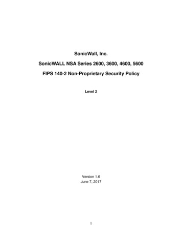
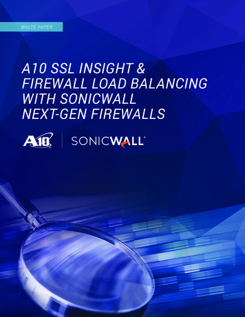
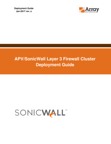
3 Detailed DescriptionFig.1 shows a detailed configuration of a Layer 3 cluster deployment (also called an L3 opensandwich).Figure 1: Deployment DetailsIn the sample deployment, the APV Series operating as an ingress load balancer is used todistribute outbound flows (LAN to WAN). The APV Series load balancer interface is configuredas a gateway for the hosts on the LAN. On egress, the flows are NAT‟ed to the individual node‟sWAN IP address or to an IP address from a NAT range that is unique on each node.4
This configuration provides full redundancy for the SonicWall firewall nodes. Failure of a node isdetected by the APV Series load balancer, at which point the load balancer stops sending thetraffic to the failed node. The failover is not stateful and therefore existing flows will be disrupted.A configuration that provides redundancy for the switch and the APV Series load balancer isdescribed in a later section.3.1 Regular LAN to WAN traffic, e.g. HTTP A packet is originated by a host on the LAN and is sent to the gateway, which is the IPaddress of the ingress APV Series load balancer. The ingress APV Series load balancer receives the packet and selects the path throughone of the nodes. „Consistent Hash‟ of source and destination IP is used as a loadbalancing algorithm. This ensures that all outbound packets for the same session orapplication have complete session visibility and inspection. The packet is received by the selected node. The node performs all configured securityfunctions – applies access rules, DPI, etc. If the packet is allowed, the packet source IP address is NAT'ed to the WAN interface IPaddress or to an IP from the WAN NAT pool range specific to the node. The response packet is routed back to the appropriate firewall node based on thepacket's destination IP, ensuring symmetric routing and full session inspection from thesame firewall node.3.2 Active FTPIn the Active FTP case, the FTP data connection is established to a NAT'ed client's IP addressthus ensuring that the data connections goes through the same node as the control connection.3.3 Passive FTPThe passive FTP connection is established between the same pair of IP addresses as thecontrol connection. Consistent Hash for Source Destination IP will select the same node. Thus,the control and data connection will go through the same node.3.4 SIPData connections are established to a NAT'ed client's IP address, ensuring that the dataconnections go through the same node as the control connection. Note that the existingoptimization allowing two SIP clients on the same network to bypass the firewall does not workin cases when two clients‟ control connections are load balanced through two different nodes5
4 Configuration Steps4.1 FirewallsIn this deployment, each firewall is expected to handle traffic in excess of 10Gbps per node.That requires a two-port LAG for ingress and egress. Configuration steps are: Create a two-port LAG - Switching/Link Aggregation Create two VLAN subinterfaces for this LAG; one LAN - VLAN100 and one WAN VLAN200 A private network is used to connect the APV Series load balancer with the nodes.Assign a unique IP to each node LAN interface, i.e. 10.2.1.1 . 10.2.1.N Assign a unique WAN interface IP to each node Optional - add a custom NAT policy for Source IP remap of outbound LAN connections4.2 Configuring the Networking Switch1. Configure the Load Balancer ingress LAG. This LAG uses LACP (conf)#interface port-channel 69 (conf-if-po-69)#description "This port channel sends traffic from LAN to LB" (conf-if-po-69)#switchport (conf-if-po-69)#no spanning-tree (conf-if-po-69)#lacp long-timeout (conf-if-po-69)#no shutdown (conf-if-po-69)#link-bundle-monitor enable2. Add interfaces to the LAG (conf)#interface Tengigabitethernet 0/0 (conf-if-te-0/0)#port-channel-protocol LACP (conf-if-te-0/0-lacp)#port-channel 69 mode active (conf-if-te-0/0-lacp)#exit (conf-if-te-0/0)#no shutdown. repeat for interfaces 0/1 through 0/73. Configure the Load Balancer egress LAG. This LAG uses LACP (conf)#interface port-channel 86 (conf-if-po-86)#description "This port channel sends traffic from LB to all firewalls" (conf-if-po-86)#switchport6
(conf-if-po-86)#no spanning-tree (conf-if-po-86)#lacp long-timeout (conf-if-po-86)#no shutdown (conf-if-po-86)#link-bundle-monitor enable4. Add interfaces to the LAG (conf)#interface Tengigabitethernet 0/8 (conf-if-te-0/0)#port-channel-protocol LACP (conf-if-te-0/0-lacp)#port-channel 69 mode active (conf-if-te-0/0-lacp)#exit (conf-if-te-0/0)#no shutdown. repeat for interfaces 0/9 through 0/155. Configure static LAG for each firewall node: (conf)#interface port-channel 1 (conf-if-po-1)#description "This is ingress and egress traffic from node 1" (conf-if-po-1)#switchport (conf-if-po-1)#channel-member TenGigabitEthernet 0/16-17 (conf-if-po-1)#no shutdown. repeat for other firewall nodes6. Create VLAN 100 for forwarding load balanced traffic from LB to the firewalls (conf)#interface vlan 100 (conf-if-vl-100)#description "LB to firewalls traffic" (conf-if-vl-100)#no ip address (conf-if-vl-100)#tagged Port-channel 1-8 (conf-if-vl-100)#untagged Port-channel 69 (conf-if-vl-100)#no shutdown7. Create VLAN 200 for forwarding traffic from the firewalls to the WAN (conf)#interface vlan200 (conf-if-vl-200)#description "Egress WAN Side Traffic" (conf-if-vl-200)#no ip address (conf-if-vl-200)#tagged Port-channel 1-87
(conf-if-vl-200)#untagged TenGigabitEthernet 0/32-39 (conf-if-vl-200)#no shutdown8. Connect LB ingress to port-channel 69 interfaces9. Connect LB egress to port-channel 86 interfaces10. Connect each firewall node to the interfaces of one of port-channel 1-84.3 Configuring the APV Series Load BalancerThe Load Balancer acts as the gateway for the LAN hosts.1. Configure ingress and egress LAG /System Configuration/Basic Networking/Link Aggregation "Bond ID" "bond1" "Bond Name" "Ingress" "Static IP Address(v4)" 10.1.1.254 Add ports 1,2,5,6,9,10,13,148
"Bond ID" "bond2" "Bond Name" "Egress" Add ports 3,4,7,8,11,12,15,16 "Static IP Address(v4)" 10.2.1.254Note, ports are evenly distributed across two NUMA Domains for more efficient performancewith symmetric load on the CPU for quicker processing .2. Add firewall nodes to 'Real Services' /Server Load Balance/Real Services/Add "Real Service Name" "Firewall1" "Real Service Type" L2IP "Real Service IP 10.2.1.19
Repeat for other nodes. The SLB Real Services Configuration screen will show all nodes.3. Enable Health Check for each firewall node in Real Services.4. Combine 'Real Services' into a group /Server Load Balance/Groups "Group Name" "Firewall Ingress-pool" "Group Method" "Consistent Hash IP" "L2 SLB Group" ON "L2 Route Policy" "direct" "L2 Hash Mode" "default" (hashes both source and destination IP)10
5. Add the remainder of the "Real Services" created at the previous step to the group. TheGroup Information screen will display them all.6. Add Virtual Service – that's the gateway for the LAN/Server Load Balance/Virtual Services11
"Virtual Service Name" "LAN Gateway" "Virtual Service Type" L2IP "Virtual Service IP" 10.1.1.1 "Associate Group" - add "Firewall Group"12
13
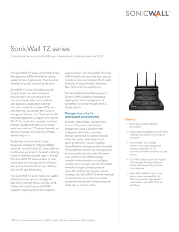
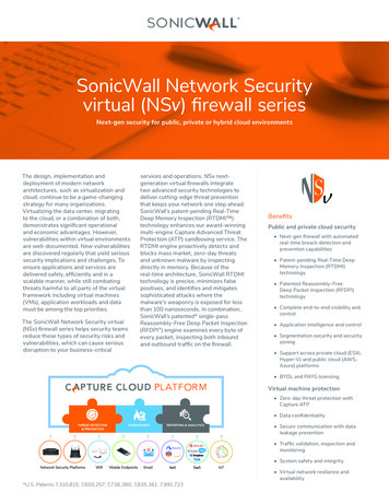
5 Fully Redundant ConfigurationThe diagram below describes a fully redundant configuration – two load balancers and twoswitches cross-linked.Figure 2: HA Configuration14
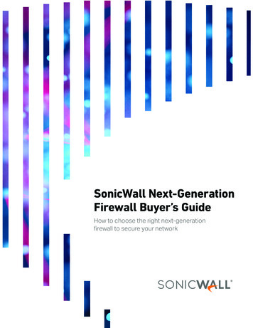
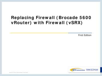
6 Support for Multiple LANsMultiple LAN support is illustrated on Fig. 3. Note that the WAN connection has been removedfor clarity. What are the main differences? Multiple Virtual Services are configured on the APV Series load balancer – one for eachLAN Multiple forwarding networks are configured between the APV Series load balancer andthe nodes – one for each LAN Multiple VLANs are added to the LAGs – one for each LANFigure 3: Support for Multiple LANs15
6.1 Regular LAN1 to LAN2 Traffic, e.g. HTTP A packet is originated by a host on the LAN1 and is sent to the gateway, which is the IPaddress of the ingress APV Series load balancer. The APV Series ingress load balancer receives the packet and selects the path throughone of the nodes. „Consistent Hash‟ of source and destination IP is used as a loadbalancing algorithm. That ensures that all outbound packets from the same flow arerouted through the same node. The packet is received by the selected node. The node performs all configured securityfunctions – applies access rules, DPI, etc. The packet is sent to back to the load balancer because it is the next hop for LAN2 The load balancer forwards the packet to the destination on LAN2 A response packet is sent. The response packet is sent to the load balancer because it is the next hop for LAN1 The load balancer selects the path through one of the nodes by using consistent hash ofsource and destination IP. Since HASH(source IP, destination IP) is the same asHASH(destination IP, source IP), the load balancer selects the same node as for LAN1to-LAN2 packet. The response packet is forwarded to the node, back to the load balancer (next hop forLAN1) and finally to the destination on LAN16.2 Active FTPActive FTP data connections are established between the same two IP addresses as the controlconnection; because HASH(source IP, destination IP) is the same as HASH(destination IP,source IP) the data connection is handled by the same node as control connection.6.3 Passive FTPThe passive FTP connection is established between the same pair of IP addresses as thecontrol connection. Consistent Hash for Source Destination IP will select the same node. Thusthe control and data connection will go through the same node.6.4 SIP6.4.1 SIP Server on the WANIf the SIP Server is located on the WAN, calls between two clients on two different LANsworks the same way as described in section 3.4, i.e. the caller connects to the NAT‟edaddress of the peer.6.4.2 SIP Server on one of the LANsThis configuration might present challenges. An incoming call from a LAN client will notalways be routed through the same node because: HASH(client 1 IP, SIP server IP) isnot the same as HASH(client 2 IP, client 1 IP). Depending on the firewall rules between16
LAN1 and LAN2 the connection may or may not go though and may not be classified asa SIP call.6.5 Additional Configuration Steps for Multi-LAN supportMulti-LAN support requires additional “Virtual Services” and additional “Real Services” on theAPV Series load balancer, one for each additional LAN. Add LAN interfaces to each node but create VLAN subinterfaces – VLAN 100, VLAN110,VLAN120Configure ingress and egress LAG: /System Configuration/Basic Networking/Link Aggregation "Bond ID" "bond1" "Bond Name" "Ingress" Add VLAN specific ips Add ports 1,2,5,6,9,10,13,14 Assign IP addresses to each new VLAN subinterface –VLAN 10, VLAN 20, VLAN 30 "Bond ID" "bond2"17
"Bond Name" "Egress" Add ports 3,4,7,8,11,12,15,16 " Add VLAN specific ips Create new „Real Services‟ on the load balancer, one for each new VLAN network onthe firewall side of load balancer The Real Services screen will display them all18
For each new LAN, create a new group on the load balancer and add corresponding„Real Services‟ to the group19
The Groups tab will display all groups created20
For each new LAN create a new „Virtual Service‟21
The Virtual Services tab will display all Virtual Services created22
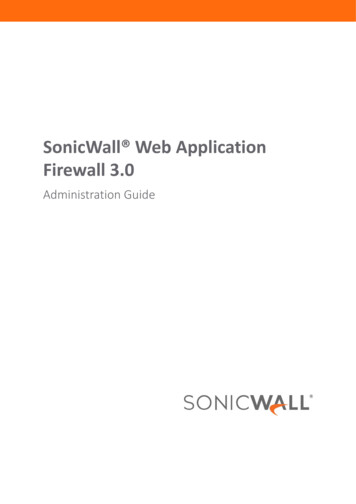
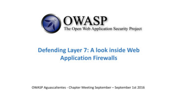
7 Support for Multiple LANs in a Fully RedundantConfigurationCombine the steps detailed in sections 5 and 6 together.Figure 4: Supporting Multiple VLANs in a Fully Redundant Configuration23
About Array NetworksArray Networks is a global leader in application delivery networking with over 5000worldwide customer deployments. Powered by award-winning SpeedCore software, Arrayapplication delivery, WAN optimization and secure access solutions are recognized byleading enterprise, service provider and public sector organizations for unmatchedperformance and total value of ownership. Array is headquartered in Silicon Valley, isbacked by over 250 employees worldwide and is a profitable company with strong investors,management and revenue growth. Poised to capitalize on explosive growth in the areas ofmobile and cloud computing, analysts and thought leaders including Deloitte, IDC and Frost& Sullivan have recognized Array Networks for its technical innovation, operationalexcellence and market s.com408-240-87001 866 orks.com 32 2 6336382Chinasupport@arraynetworks.com.cn 010-84446688Indiaisales@arraynetworks.com 91-080-41329296France and North Africainfosfrance@arraynetworks.com 33 6 07 511 868Japansales-japan@arraynetworks.com 81-44-589-8315To purchaseArray NetworksSolutions, pleasecontact yourArray Networksrepresentative at1-866-MY-ARRAY(692-7729) orauthorized resellerJan-2017 rev. a 2017 Array Networks, Inc. All rights reserved. Array Networks and the Array Networks logo are trademarks of Array Networks, Inc. inthe United States and other countries. All other trademarks, service marks, registered marks, or registered service marks are theproperty of their respective owners. Array Networks assumes no responsibility for any inaccuracies in this document. Array Networksreserves the right to change, modify, transfer, or otherwise revise this publication without notice.24
capacity of the SonicWall NGFW for outbound traffic (LAN to WAN) through APV Series load balancing. The deployment supports traffic originated by the clients on the LAN and correctly routes dependent flows such as inbound SIP calls originated on the WAN. In this network configuration, one APV Series Load Balancer distributes outbound traffic across