Transcription
DD BOOST IMPLEMENTATIONWITH NETWORKERCrescenzo OlivieroAdvisory System EngineerEMC Computer Systems Italia S.p.Acrescenzo.oliviero@emc.com
Table of ContentsIntroduction . 3Why DD Boost is so important . 5Easy to manage: DD monitoring from NMC . 7Backup and restore performance . 7Network Traffic reduction and Source Deduplication . 8Client CPU consumption and performance. 10Clone controlled replication . 13Implementation Procedure . 15DD Boost Network Requirements . 15Manual DD Boost implementation . 16Manual creation with nsradmin -visual . 23Data Flow control . 25Data Domain Networking possibilities . 27Configuring Link Aggregation Control Protocol . 27Routing rules . 29Configuring Link Aggregation (Active Only) . 30VLANs and VLAN Tagging (802.1Q) . 31IP Aliasing . 33Support Statement . 34Disclaimer: The views, processes, or methodologies published in this article are those of theauthor. They do not necessarily reflect EMC Corporation’s views, processes, ormethodologies.2014 EMC Proven Professional Knowledge Sharing2
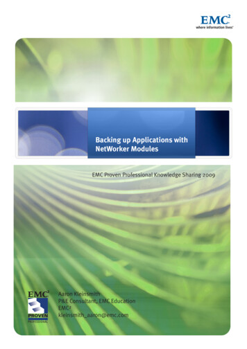
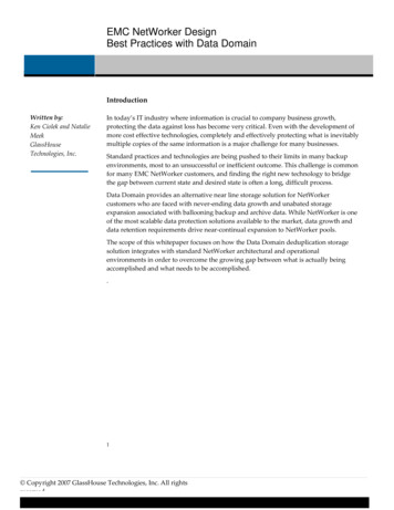
IntroductionEnterprise customer environments are often implemented with complex networkinfrastructures where different networks are isolated for security reasons. A typical enterprisecustomer has a single NetWorker Management Console (NMC) that manages differentdatazones and Data Domain systems as seen in the figure below (only one datazone iscompletely expanded for sake of simplicity).In environments with only one datazone and NMC is implemented on NetWorker server itselfor does not have complex network environment, the standard procedure to implement DDBoost is fine. Using the wizard, Boost backup will start in 5 minutes.In environments where there are different isolated VLANs where clients reside, NMC will notbe able to see all networks where data will flow and wizard configuration could fail.To configure Boost devices, NMC must see both NetWorker servers and Data Domainsystems over the backup network where the Boost device will be enabled and data will flow.For security reasons, this is typically not possible, and interferes with Boost deviceimplementation.2014 EMC Proven Professional Knowledge Sharing3
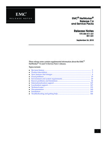
The following picture shows the desired configuration where NMC is confined on themanagement network.A procedure described later in this article will permit DD Boost device creation on differentnetworks, enabling source deduplication that will avoid network congestion and reducebackup windows.2014 EMC Proven Professional Knowledge Sharing4
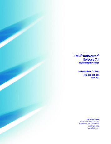
Why DD Boost is so importantDD Boost technology is important for many reasons. First, it can be implemented forperformance purposes: it is already available for different environments and is able to shrinkbackup windows and reduce network traffic by up to 95%.The figure below depicts what can be done today even without using NetWorker.Moreover, using Data Domain with NetWorker will provide many other benefits as shown inthe following figure.2014 EMC Proven Professional Knowledge Sharing5
The most important feature is enablement of client direct feature; this will implement sourcededuplication anywhere!Client direct is described below:2014 EMC Proven Professional Knowledge Sharing6
Any client will send backup data directly to DataDomain device by-passing storage nodes,this will result in removal of any bottleneck increasing backup speed.Easy to manage: DD monitoring from NMCIntegrating Data Domain with NMC enables the Data Domain monitoring feature as backupstorage as seen below (SNMP). This reduces management effort since that backupmanager will operate only on one console:This integration provides the status of the Data Domain device, the utilization, how muchspace is left, if it is fine, and so on. No other tools are required to gain visibility of the DataDomain device.This feature simplifies use of Data Domain and relieves you of having to manage a virtualtape library, create drives, manage tapes, and more.Backup and restore performanceThe following figure depicts how DD Boost improves Data Domain performance and reducesbackup windows of the entire infrastructure.2014 EMC Proven Professional Knowledge Sharing7
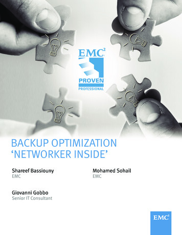
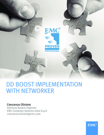
DD Boost provides a performance improvement greater than 100% (more than doublingData Domain performance), without impacting client performance or including hardware.Network Traffic reduction and Source DeduplicationDD Boost deduplicates most of the data at source, close to where data lives, reducingnetwork traffic, lowering CPU consumption, and shrinking backup windows.The following figure shows a test conducted during a Proof of Concept (POC). Data are sentto Data Domain system over the network. This is the first backup of virtual machines on aVMware farm.2014 EMC Proven Professional Knowledge Sharing8
Even at first backup, data sent over network are less than 10% of the total amount. Atsecond backup—done 4 hours later—the amount of data sent over the LAN is negligible.2014 EMC Proven Professional Knowledge Sharing9
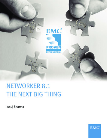
This is a key reason why DD Boost is so important! No other backup software backupapplicance can do the same on every client on the infrastructure.Network traffic reduction is vital in virtualized environments where consolidation could lead tomany virtual machines being backed up at the same time, on the same ESX, using the sameGbit Ethernet connection to the backup infrastructure.The above result is easily repeatable with a client installed within a virtual machine (this caseis necessary when the virtual machine uses Raw Device Mapping which is not compatiblewith VADP snapshots), on physical systems, or on machines containing applications such asdatabases.Client CPU consumption and performanceSource deduplication reduces CPU consumption on the client compared to a standardbackup procedure where all data will flow to the backup device.The screenshot below is an example of CPU consumption during a backup session.2014 EMC Proven Professional Knowledge Sharing10
Processes save.exe (two parallel backup jobs) is consuming less than 13% CPU on thisWindows server sending out about 100MB/s precompressed data using only a few KB/s ofeffective network bandwitdth (2nd backup session where deduplication is working a lot).2014 EMC Proven Professional Knowledge Sharing11
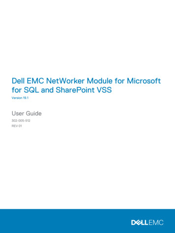
The following figure displays the backup job summary.2014 EMC Proven Professional Knowledge Sharing12
The figure shows that about 8GB backs up in 36 seconds (first save.exe) and 93GB of databacks up in about 21 minutes (second save.exe process).Clone controlled replicationAnother benefit of DD Boost implementation with NetWorker is clone-controlled replication.Cloning data, even to another site, is a simple clone policy job to be implemented only onNetWorker server. Behind the scenes, this will use Data Domain deduplication to reducebandwidth requirements. NetWorker will know at any time that there are other copies of thedata on another site on another Data Domain with the possibility of restoring data from thesecond copy.As of NetWorker 8.1, the clone process will start at the end of each job reducing time todisaster recovery with an elegant and low-cost backup solution.2014 EMC Proven Professional Knowledge Sharing13
The figure below is an example of clone infrastructure (10 Gbit and storage nodes are notstrictly required).The gain here with DD Boost is that clone policy are done on NetWorker which knows whereclones of data are and is able to restore it on a remote site or on a primary site if networkbandwidth between sites is enough to comply with SLA.Nothing has to be done on the Data Domain side (replication is managed by NetWorker).2014 EMC Proven Professional Knowledge Sharing14
Implementation ProcedureNetwork rules to be satisfied in order to implement DD Boost are shown below.DD Boost Network RequirementsTo realize full benefits of DD Boost implementation, each client must be able to see the DDBoost device directly. If this is satisfied, data will go directly to Data Domain, by-passingstorage nodes and NetWorker server.Clients, NetWorker servers, and storage nodes must be able to resolve the Data Domain IP,use DNS, or local host file to have this implemented.Data flow is shown in the following figure where network requirement is also shown.The following are the network ports that must be opened to ensure correct implementation ofDD Boost among NetWorker server, Data Domain, and NMC.2014 EMC Proven Professional Knowledge Sharing15
NMC is confined in a management network for security reasons and is typically is not able toaccess Data Domain over all the network where data will flow.In any case, there must be a direct connection between clients and Data Domain toimplement DD Boost with direct client.Manual DD Boost implementation Enable DD Boost on Data Domain as usualAdd a DD Boost user# user add username [password password]For example, to add a user with a login name of crexboost and a password of abc123with administrative privilege, enter:# user add crexboost password abc123The user must be configured in the application in order to connect to the Data Domainsystem.Set the DD Boost user by entering:# DD Boost set user-name crexboostDD Boost user set to usernamePrevious user: none setNote: Only one DD Boost user can be configured at a time for DD Boost access on aData Domain system. The username and password must have already been set up onthe Data Domain system using the DD Boost CLI command.Enable DD Boost by entering:# DD Boost enableDD Boost enabled2014 EMC Proven Professional Knowledge Sharing16
Create Storage UnitsOn the Data Domain system, enter:# DD Boost storage-unit create storage unit name-suwhere each SU name is unique and tipically is the name of NetWorker datazone(NetWorker hostname).Repeat the procedure for each Storage unit that is to be created. Log on to the NMC and go to the datazone where you are implementing DD Boost.Create a generic device paying attention to the following three parameters:1. Device access information: useDNS Data Domain Name:/StorageunitName/devicename2. Media type: must be Data Domain3. Remote user and password (the one you set on Data Domain side as DDBoost user)2014 EMC Proven Professional Knowledge Sharing17
At this point, you are able to see newer Data Domain device from NetWorker GUI.You are not able to mount and label new devices at this time. Since we are not using aWizard, we missed folders creation on the Data Domain side (though Wizard will do itautomatically, NMC must see Data Domain).2014 EMC Proven Professional Knowledge Sharing18
To solve this, mount via NFS or CIFS Data Domain folder and create folder structuremanually. The following example is for a Linux box where network name of Data Domain isData Domain, storage unit created on Data Domain is named NetWorker (dns name ofNetWorker server is NetWorker), mounting it on local folder /DDSU:Mount –t nfs Data Domain name:/data/col1/StorageUnit /local folder to mount2014 EMC Proven Professional Knowledge Sharing19
Create a folder with DD Boost device name (mkdir manualdevice) and change its owner tomatch DD Boost user.You can now mount and label the newer device on the NetWorker side since you created thefolder under storage unit.This is the effect on the Linux folder we mounted before. NetWorker created all Booststructure on it:You can now label the device and create a pool to write data on it.2014 EMC Proven Professional Knowledge Sharing20
2014 EMC Proven Professional Knowledge Sharing21
The same procedure applies when creating an indexing device on Data Domain.Mkdir /DDSU/manualindexFollowing this, use the GUI to create a generic device as before, defining it as index pool.2014 EMC Proven Professional Knowledge Sharing22
You are now able to back up data on the DD Boost device you have just created, indexingincluded!Manual creation with nsradmin -visualAnother way to configure Boost device is via nsradmin command to be launched onNetWorker server. The procedure to follow is shown below:2014 EMC Proven Professional Knowledge Sharing23
Log on to NetWorker server and issue command: nsradmin –visualYou should land here where you can create a new device.What you find may differ slightly depending on NetWorker version, but the summary is thesame. Shown here is what you see with version 7.6.x.Shown here is what you will see with version 8.0.x:2014 EMC Proven Professional Knowledge Sharing24
Parameters to consider are the same as before: Device access information Media type Remote user (DD Boost one) and passwordProcedure flows exactly the same as before with Data Domain folder creation, mounting andlabelling newer device.Data Flow controlThere are different approaches to control that clients are sending data directly to DataDomain.1. On the Data Domain side, the command: DD Boost show connection provides alist of the clients that are sending data directly to Data Domain via DD Boost protocol.An example is shown below:2014 EMC Proven Professional Knowledge Sharing25
2. On NetWorker Server, look at daemon.log which should display DDCL or direct clientsave with the client name you are backing up, An example is shown below.2014 EMC Proven Professional Knowledge Sharing26
Data Domain Networking possibilitiesData Domain offers different methods to configure networking: Link aggregation control Protocol VLANs and VLAN Tagging IP aliasingThe most appropriate configuration is to use link aggregation (e.g. 2x10Gbit or 8x1Gbit) and,on the created channels, configure all IP addresses you need to go on different networkVLANs.The figure below shows an example of 8 Gbit connections aggregated into two differentaggregations where it is possible to create VLANs you need for configuration.It is not possible to use DD Boost ifgroup feature in this type of configuration.Configuring Link Aggregation Control ProtocolLink Aggregation Protocol (LACP) is a bonding protocol used to provide active coordinationor link status via “heartbeat” messages and failure handling of links that experience issues.LACP is limited to configuration on a single switch.2014 EMC Proven Professional Knowledge Sharing27
When setting up a LACP link, several parameters can be set that affect the performance ofthe bond; slow / fast timers, up / down timers, and the hash algorithm used. The slow / fast option determines how often a heartbeat message is sent todetermine link status. The default for slow is 30 seconds. Fast changes the option toone second. The up / down option determines how long LACP will wait before reacting to a linkstate change. The value is set in milliseconds and in intervals of .9 seconds. The hash algorithm determines which variables will be used to perform link selection.Note: It is very important to select the proper load balancing algorithm as the differingoptions can significantly affect data transfer rates and thereby, performance.The net aggregate command creates a virtual interface with the specified physicalinterfaces and uses one of three aggregation modes. Select the mode that is compatible withthe switch: xor-L2Xor Layer 2 transmits packets based on static balanced mode aggregation with a Xor hashof Layer 2 (inbound and outbound MAC addresses). xor-L3L4Xor Layer 3/4 transmits packets based on static balanced mode aggregation with a Xor hashof Layer 3 (inbound and outbound IP address) and Layer 4 (inbound and outbound portnumbers).1. [ ] Disable each of the interfaces that you plan to use as aggregation interfaces, suchas eth2a and eth3, by entering:# net disable eth3a# net disable eth3b2. [ ] To create a virtual interface, use the net create command and choose a virtualinterface. For example:# net create virtual veth13. [ ] Enter:# net aggregate add virtual-ifname mode {roundrobin lacp hash {xor-L2 xorL2L3 xorL3L4}interfaces physical-ifnamelist2014 EMC Proven Professional Knowledge Sharing28
For example, to create a virtual interface veth1 from the two physical interfaces eth3aand eth3b, using the mode xor-L2, enter:# net aggregate add veth1 mode lacp hash xor-L2 interfaces eth3a eth3bNote: Optional command variables can be added to this command, as needed bynetwork conditions. Those options are rate {fast / slow}, up / down {time}4. [ ] To verify that the interface has been created, enter:# net aggregate showThe output displays the name of the virtual interface, its hardware address, aggregationmode, and the ports that comprise the virtual interface.Note: Do not assign an IP address at the time of creating VLAN interfaces on anaggregated interface. Assign an IP address at the time of VLAN configuration.5. [ ] Assign an IP address to the new interface using this command:# net config ifname ipaddrwhere ifname is the name of the interface, which is veth1 in this example, and ipaddr isthe interface’s IP address.Routing rulesTo work properly, correct routing rules must be set on Data Domain to keep data traffic in/outon the same network to prevent asymmetric traffic blocked by default on the firewalls.Below is an example of the configuration of originating box:# net show onon/an/an/an/a----IP ----------additional setting------------------------------------This is the routing table before any changes have been made# route show 0255.0.0.00.0.0.0FlagsUUUUUG2014 EMC Proven Professional Knowledge 2loeth029
In this example, we will be adding a route to 172.28.0.207 and want traffic bound for thataddress to egress Ethernet interface 2.Use either of the following commands to add a route where a host uses a specific interface(please note the hostname is resolved before being inserted into the routing table):# route add 172.28.0.207 eth2Add a route to change the egress location:# route add -host bob.chew.net eth2# route show tableKernel IP routing 0.00.0.0.0172.28.0.00.0.0.0172.28.0.00
access Data Domain over all the network where data will flow. In any case, there must be a direct connection between clients and Data Domain to implement DD Boost with direct client. Manual DD Boost implementation Enable DD Boost on Data Domain as usual Add a DD Boost user # user add username [password password]