Transcription
Chapter 3Basic Plasma Physics3.1 IntroductionElectric propulsion achieves high specific impulse by the acceleration ofcharged particles to high velocity. The charged particles are produced byionization of a propellant gas, which creates both ions and electrons and formswhat is called a plasma. Plasma is then a collection of the various chargedparticles that are free to move in response to fields they generate or fields thatare applied to the collection and, on the average, is almost electrically neutral.This means that the ion and electron densities are nearly equal, ni ne , acondition commonly termed “quasi-neutrality.” This condition existsthroughout the volume of the ionized gas except close to the boundaries, andthe assumption of quasi-neutrality is valid whenever the spatial scale length ofthe plasma is much larger than the characteristic length over which charges orboundaries are electrostatically shielded, called the Debye length. The ions andelectrons have distributions in energy usually characterized by a temperature Tifor ions and Te for electrons, which are not necessarily or usually the same. Inaddition, different ion and electron species can exist in the plasma withdifferent temperatures or different distributions in energy.Plasmas in electric propulsion devices, even in individual parts of a thruster,can span orders of magnitude in plasma density, temperature, and ionizationfraction. Therefore, models used to describe the plasma behavior andcharacteristics in the thrusters must be formed with assumptions that are validin the regime being studied. Many of the plasma conditions and responses inthrusters can be modeled by fluid equations, and kinetic effects are onlyimportant in specific instances.There are several textbooks that provide very comprehensive introductions toplasma physics [1–3] and the generation of ion beams [4]. This chapter is37
38Chapter 3intended to provide the basic plasma physics necessary to understand theoperation of ion and Hall thrusters. The units used throughout the book arebased on the International System (SI). However, by convention we willoccasionally revert to other metric units (such as A/cm2, mg/s, etc.) commonlyused in the literature describing these devices.3.2 Maxwell’s EquationsThe electric and magnetic fields that exist in electric propulsion plasmas obeyMaxwell’s equations formulated in a vacuum that contains charges andcurrents. Maxwell’s equations for these conditions are E o E B t(3.2-1)(3.2-2) B 0(3.2-3) E B μo J o, t(3.2-4)where is the charge density in the plasma, J is the current density in theplasma, and o and μo are the permittivity and permeability of free space,respectively. Note that and J comprise all the charges and currents for all theparticle species that are present in the plasma, including multiply charged ions.The charge density is then qs ns e ( Zni ne ) ,(3.2-5)swhere qs is the charge state of species s, Z is the charge state, ni is the ionnumber density, and ne is the electron number density. Likewise, the currentdensity isJ qs ns vs e ( Zni vi ne ve ) ,(3.2-6)swhere vs is the velocity of the charge species, vi is the ion velocity, and ve isthe electron velocity. For static magnetic fields ( B t 0) , the electric fieldcan be expressed as the gradient of the electric potential,
Basic Plasma Physics39E ,(3.2-7)where the negative sign comes from the convention that the electric fieldalways points in the direction of ion motion.3.3 Single Particle MotionsThe equation of motion for a charged particle with a velocity v in a magneticfield B is given by the Lorentz force equation:F mdv q ( E v B) .dt(3.3-1)Particle motion in a magnetic field in the zˆ direction for the case of negligibleelectric field is found by evaluating Eq. (3.3-1): vx qBvy t vym –qBvx t vm z 0. tm(3.3-2)Taking the time derivative of Eq. (3.3-2) and solving for the velocity in eachdirection givesqB vy qB vx2 m m t t2 2 vx 2 vy2qB vx qB vy .2 m m t t(3.3-3)These equations describe a simple harmonic oscillator at the cyclotronfrequency: c qB.m(3.3-4)For electrons, this is called the electron cyclotron frequency.The size of the particle orbit for finite particle energies can be found from thesolution to the particle motion equations in the axial magnetic field. In thiscase, the solution to Eq. (3.3-3) is
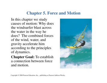
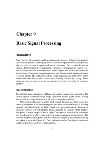
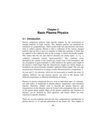
40Chapter 3vx,y v ei c t .(3.3-5)The equation of motion in the y-direction in Eq. (3.3-2) can be rewritten asvy m vx1 vx .qB t c t(3.3-6)Utilizing Eq. (3.3-5), Eq. (3.3-6) becomesvy 1 vx y iv ei c t . c t t(3.3-7)Integrating this equation givesvy yo ei c t . c(3.3-8)Taking the real part of Eq. (3.3-8) givesvy yo cos ct rL cos ct , c(3.3-9)where rL v / c is defined as the Larmor radius. A similar analysis of thedisplacement in the x̂ direction gives the same Larmor radius 90 degrees out ofphase with the ŷ -direction displacement, which then with Eq. (3.3-9) describesthe particle motion as a circular orbit around the field line at xo and yo with aradius given by rL .The Larmor radius arises from very simple physics. Consider a charged particleof mass, m, in a uniform magnetic field with a velocity in one direction, asillustrated in Fig. 3-1. The charge will feel a Lorentz forceF qv B .(3.3-10)Since the charged particle will move under this force in circular orbits in thev B direction, it feels a corresponding centripetal force such that
Basic Plasma Physicsmv 2Fc qv B ,r41L(3.3-11)where r is the radius of the cycloidal motionin the magnetic field. Solving for the radiusof the circle givesr rL mv ,qB(3.3-12)which is the Larmor radius.The Larmor radius can be written in a formsimple to remember:q.?*Fig. 3-1. Positively charged particlemoving in a uniform verticalmagnetic field.v1 2mV rL , c Be(3.3-13)using 1 2 mv 2 eV for the singly charged particle energy in the directionperpendicular to the magnetic field. The direction of particle gyration is alwayssuch that the induced magnetic field is opposite in direction to the applied field,which tends to reduce the applied field, an effect called diamagnetism. Anyparticle motion along the magnetic field is not affected by the field, but causesthe particle motion to form a helix along the magnetic field direction with aradius given by the Larmor radius and a pitch given by the ratio of theperpendicular to parallel velocities.Next consider the situation in Fig. 3-1, but with the addition of a finite electricfield perpendicular to B. In this case, E is in some direction in the plane of thepage. The equation of motion for the charged particle is given by Eq. (3.3-1).Considering the drift to be steady-state, the time derivative is equal to zero, andEq. (3.3-1) becomesE v B .(3.3-14)Taking the cross product of both sides with B givesE B ( v B ) B vB 2 B ( B v ) .(3.3-15)The dot product is in the direction perpendicular to B, so the last term inEq. (3.3-15) is equal to zero. Solving for the transverse velocity of the particlegives
42Chapter 3v E BB2 vE ,(3.3-16)which is the “E cross B” drift velocity. In this case, the drift is in the directionperpendicular to both E and B, and arises from the cycloidal electron motion inthe magnetic field being accelerated in the direction of –E and decelerated inthe direction of E. This elongates the orbit on one-half cycle and shrinks theorbit on the opposite half cycle, which causes the net motion of the particle inthe E B direction. The units of the E B velocity arevE E [V/ m](m/ s) .B [tesla](3.3-17)Finally, consider the situation of a particle gyrating in a magnetic field that ischanging in magnitude along the magnetic field direction zˆ . This is commonlyfound in electric propulsion thrusters relatively close to permanent magnets orelectromagnetic poles-pieces that produce fields used to confine the electrons.Since the divergence of B is zero, Eq. (3.2-3), the magnetic field in cylindricalcoordinates is described by B1 rBr ) z 0 .( zr r(3.3-18)Assuming that the axial component of the field does not vary significantly withr and integrating yields the radial component of the magnetic field with respectto r,Br r Bz.2 z(3.3-19)The Lorentz force on a charged particle has a component along zˆ given byFz qv Br ,(3.3-20)where the azimuthal particle velocity averaged over a Larmor-radius ( r rL )gyration is v v . The average force on the particle is thenFz 1 mv 2 Bz.2 B zThe magnetic moment of the gyrating particle is defined as(3.3-21)
Basic Plasma Physics43μ 1 mv 2.2 B(3.3-22)As the particle moves along the magnetic field lines into a stronger magnitudefield, the parallel energy of the particle is converted into rotational energy andits Larmor radius increases. However, its magnetic moment remains invariantbecause the magnetic field does no work and the total kinetic energy of theparticle is conserved. For a sufficiently large increase in the field, a situationcan arise where the parallel velocity of the particle goes to zero and the Lorentzforce reflects the particle from a “magnetic mirror.” By conservation of energy,particles will be reflected from the magnetic mirror if their parallel velocity isless thanv v Rm 1 ,(3.3-23)where v is the parallel velocity and Rm is the mirror ratio given byBmax / Bmin . This effect is used to provide confinement of energetic electronsin ion-thruster discharge chambers.There are a number of other particle drifts and motions possible that depend ongradients in the magnetic and electric fields, and also on time-dependent oroscillating electric or magnetic fields. These are described in detail in plasmaphysics texts such as Chen [1], and while they certainly might occur in theelectric propulsion devices considered here, they are typically not of criticalimportance to the thruster performance or behavior.3.4 Particle Energies and VelocitiesIn ion and Hall thrusters, the charge particles may undergo a large number ofcollisions with each other, and in some cases with the other species (ions,electrons, and/or neutrals) in the plasma. It is therefore impractical to analyzethe motion of each particle to obtain a macroscopic picture of the plasmaprocesses that is useful to for assessing the performance and life of thesedevices. Fortunately, in most cases it is not necessary to track individualparticles to understand the plasma dynamics. The effect of collisions is todevelop a distribution of the velocities for each species. On the average, and inthe absence of other forces, each particle will then move with a speed that issolely a function of the macroscopic temperature and mass of that species. Thecharged particles in the thruster, therefore, can usually be described by differentvelocity distribution functions, and the random motions can be calculated bytaking the moments of those distributions.
44Chapter 3Most of the charged particles in electric thrusters have a Maxwellian velocitydistribution, which is the most probable distribution of velocities for a group ofparticles in thermal equilibrium. In one dimension, the Maxwellian velocitydistribution function is m f (v) 2 kT mv 2 exp , 2kT 1/2(3.4-1)where m is the mass of the particle, k is Boltzmann’s constant, and the width ofthe distribution is characterized by the temperature T. The average kineticenergy of a particle in the Maxwellian distribution in one dimension is Eave 1 – 2 mv – 2f (v) dv.(3.4-2)f (v) dvBy inserting in Eq. (3.4-1) and integrating by parts, the average energy perparticle in each dimension isEave 1kT .2(3.4-3)If the distribution function is generalized into three dimensions, Eq. (3.2-8)becomes mf (u,v,w) 2 kT3/2() mexp u 2 v 2 w 2 ,2kT (3.4-4)where u, v, and w represent the velocity components in the three coordinateaxes. The average energy in three dimensions is found by inserting Eq. (3.4-2)in Eq. (3.4-4) and performing the triple integration to giveEave 3kT .2(3.4-5)The density of the particles is found fromn – nf (v) dv m n – 2 kT 3/2() m u 2 v 2 w 2 dudvdw .exp 2kT(3.4-6)
Basic Plasma Physics45The average speed of a particle in the Maxwellian distribution is m v v 0 2 kT 3/2 v2 exp – 2 4 v 2 dv , vth(3.4-7)where v in Eq. (3.4-7) denotes the particle speed and vth is defined as(2kT / m)1/2 . Integrating Eq. (3.4-7), the average speed per particle is 8kT v m 1/2.(3.4-8)The flux of particles in one dimension (say in the zˆ direction) for a Maxwelliandistribution of particle velocities is given by n vz . In this case, the averageover the particle velocities is taken in the positive vz direction because the fluxis considered in only one direction. The particle flux (in one direction) is then z nvz f (v)d 3v,(3.4-9)which can be evaluated by integrating the velocities in spherical coordinateswith the velocity volume element given byd 3 v v 2 dvd v 2 dv sin d d ,(3.4-10)where the d represents the element of the solid angle. If the incident velocityhas a cosine distribution ( vz v cos ), the one-sided flux is m z n 2 kT3/22 0d /20sin d v2 2v cos exp –v dv , (3.4-11)0 vth which gives11 8kT z nv n 44 m 1/2.(3.4-12)Since the plasma electrons are very mobile and tend to make a large number ofcoulomb collisions with each other, they can usually be characterized by aMaxwellian temperature Te and have average energies and speeds welldescribed by the equations derived in this section. The random electron fluxinside the plasma is also well described by Eq. (3.4-12) if the electron
46Chapter 3temperature and density are known. The electrons tend to be relatively hot(compared to the ions and atoms) in ion and Hall thrusters because theytypically are injected into the plasma or heated by external mechanisms
The units used throughout the book are based on the International System (SI). However, by convention we will occasionally revert to other metric units (such as A/cm2, mg/s, etc.) commonly used in the literature describing these devices. 3.2 Maxwell’s Equations The electric and magnetic fields that exist in electric propulsion plasmas obey Maxwell’s equations formulated in a vacuum that .